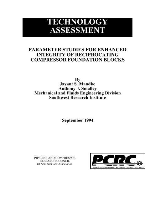
TECHNOLOGY ASSESSMENT - ANSYS Users
TECHNOLOGY ASSESSMENT - ANSYS Users
TECHNOLOGY ASSESSMENT - ANSYS Users

You also want an ePaper? Increase the reach of your titles
YUMPU automatically turns print PDFs into web optimized ePapers that Google loves.
<strong>TECHNOLOGY</strong><br />
<strong>ASSESSMENT</strong><br />
PARAMETER STUDIES FOR ENHANCED<br />
INTEGRITY OF RECIPROCATING<br />
COMPRESSOR FOUNDATION BLOCKS<br />
By<br />
Jayant S. Mandke<br />
Anthony J. Smalley<br />
Mechanical and Fluids Engineering Division<br />
Southwest Research Institute<br />
PIPELINE AND COMPRESSOR<br />
RESEARCH COUNCIL<br />
Of Southern Gas Association<br />
September 1994<br />
Pipeline & Compressor Research Council est 1952
This document contains information resulting from a cooperative research effort.<br />
The contents hereof are only intended to be guidelines for the subject matter to<br />
which the document pertains. Neither Southern Gas Association nor the Gas<br />
Machinery Research Council make any warranty or representation, express or<br />
implied, with respect to the accuracy, completeness or usefulness of the<br />
information contained in this document, including, without limitation, implied<br />
warranties of merchantability and fitness for a particular purpose, or that the use<br />
of any method, suggestion, technology, information or guidelines disclosed herein<br />
may not infringe on rights owned or claimed by others. In no event will Southern<br />
Gas Association or the Gas Machinery Research Council be liable for any<br />
damages, including, without limitation, liability arising out of contract,<br />
negligence, strict liability, environmental or tort, warranty or copyright<br />
infringement, or any incidental or consequential damage arising out of the use of<br />
this Report. The user assumes any liability with respect to any methods,<br />
suggestions, technology, guidelines or other information contained herein and<br />
releases Southern Gas Association and the Gas Machinery Research Council from<br />
any and all damage, loss or injury having to do with use of any such methods,<br />
suggestions, technology, guidelines or other such information.<br />
This document may contain references to product(s) which may assist in<br />
achieving one or more guidelines as may be set forth herein. Such references are<br />
not intended to constitute endorsement or criticism of any such product(s) by the<br />
Gas Machinery Research Council or Southwest Research Institute. Any<br />
attempted use of this Report, or its contents, by anyone, as an endorsement or<br />
criticism of any such product(s) is expressly prohibited. Neither this Report or its<br />
contents may be used for any advertising purposes whatsoever.<br />
GMRC PURPOSE<br />
The Gas Machinery Research Council provides member companies and industry with the<br />
benefits of an applied research and technology program directed toward improving<br />
reliability and cost effectiveness of the design, construction, and operation of mechanical<br />
and fluid systems.<br />
For additional copies of this report, please contact:<br />
Marsha Short<br />
Director, Member Services<br />
Gas Machinery Research Council<br />
3030 LBJ Freeway, Suite 1300, L.B. 60<br />
Dallas, TX 75234<br />
Telephone (972) 620-4024<br />
FAX (972) 620-8518<br />
ii
TABLE OF CONTENTS<br />
I. INTRODUCTION ...................................................... 1<br />
II. FOUNDATION BLOCK DETAILS..................................... 3<br />
iii<br />
Page<br />
A. Material Properties.......................................................3<br />
B. Shaking Forces ............................................................4<br />
C. Anchor Bolt Preload......................................................6<br />
III. FINITE ELEMENT MODEL ........................................... 7<br />
IV. PARAMETRIC STUDIES .............................................11<br />
A. Anchor Bolt Preload.....................................................11<br />
B. Anchor Bolt Length ......................................................12<br />
C. Anchor Bolt Configuration .............................................13<br />
D. Rebar Density ............................................................14<br />
E. Concrete Strength........................................................14<br />
F. Shaking Forces ...........................................................15<br />
V. INTERACTION OF ANCHOR BOLT PRELOAD AND<br />
SHAKING FORCES ...................................................16<br />
VI. DISCUSSION OF RESULTS ..........................................18<br />
VII. SUMMARY ..........................................................21<br />
VIII. RECOMMENDATIONS...............................................24<br />
IX. REFERENCES ........................................................25
Figure<br />
LIST OF ILLUSTRATIONS<br />
II-1 Foundation Block Isometric View—Complete Installation .....................27<br />
II-2 Foundation Block Section Through Bolts..........................................28<br />
III-1 Foundation Block Isometric View—Compressor Area Showing<br />
Grout Pocket and Sole Plates ........................................................29<br />
III-2 Half Symmetry Finite Element Model—for 4 Cylinders ........................30<br />
III-3 Truncated Half Symmetry Model—for 1 Cylinder ...............................31<br />
III-4 Truncated Half Symmetry Model—Reduced Height.............................31<br />
III-5 Contours of Principal Stress (S1)—Reference Case..............................32<br />
III-6 Vertical Axis Stress—Reference Case .............................................32<br />
III-7 Elements Cracked at 5th Integration Point—Reference Case ...................33<br />
III-8 Map of Cracked Elements—Reference Case ......................................33<br />
III-9 Vertical Stress Contours—Reference Case ........................................34<br />
IV-1 Contours of Principal Stress (S1)—Effect of Preload ............................35<br />
IV-2 Map of Cracked Elements—Effect of Preload ....................................35<br />
IV-3 Contours of Principal Stress (S1)—Effect of Preload ............................36<br />
IV-4 Map of Cracked Elements—Effect of Preload ....................................36<br />
IV-5 Contours of Principal Stress (S1)—Effect of Preload ............................37<br />
IV-6 Map of Cracked Elements—Effect of Preload ....................................37<br />
IV-7 Contours of Principal Stress (S1)—Effect of Preload ............................38<br />
IV-8 Map of Cracked Elements—Effect of Zero Preload..............................38<br />
IV-9 Contours of Principal Stress (S1)—Effect of Free Standing<br />
Anchor Bolt Length ..................................................................39<br />
IV-10 Map of Cracked Elements—Effect of Free Standing<br />
Anchor Bolt Length ...................................................................39<br />
iv<br />
Page
Figure<br />
LIST OF ILLUSTRATIONS<br />
Continued<br />
IV-11 Contours of Principal Stress (S1)—Effect of Free Standing<br />
Anchor Bolt Length ..................................................................40<br />
IV-12 Map of Cracked Elements—Effect of Free Standing<br />
Anchor Bolt Length ...................................................................40<br />
IV-13 Elements Cracked at 5th Integration Point—Effect of Free Standing<br />
Anchor Bolt Length ...................................................................41<br />
IV-14 Contours of Principal Stress (S1)—Effect of Partially Embedded<br />
Embedded Length .....................................................................41<br />
IV-15 Map of Cracked Elements—Effect of Partially Embedded Length ............42<br />
IV-16 Elements Cracked at 5th Integration Point—Effect of Partially<br />
Embedded Length .....................................................................42<br />
IV-17 Contours of Principal Stress (S1)—Effect of Free Standing<br />
Bolt Through-to-the-Mat .............................................................43<br />
IV-18 Elements Cracked at 5th Integration Point—Effect of Free Standing<br />
Bolt Through-to-the-Mat .............................................................43<br />
IV-19 Contours of Principal Stress (S1)—Effect of Rebar Density ....................44<br />
IV-20 Map of Cracked Elements—Effect of Rebar Density ............................44<br />
IV-21 Contours of Principal Stress (S1)—Effect of Rebar Density ....................45<br />
IV-22 Map of Cracked Elements—Effect of Rebar Density ............................45<br />
IV-23 Contours of Principal Stress (S1)—Effect of Rebar Density ....................46<br />
IV-24 Map of Cracked Elements—Effect of Rebar Density ............................46<br />
IV-25 Contours of Principal Stress (S1)—Effect of Rebar Density ....................47<br />
IV-26 Map of Cracked Elements—Effect of Rebar Density ............................47<br />
IV-27 Contours of Principal Stress (S1)—No Rebar .....................................48<br />
IV-28 Map of Cracked Elements—No Rebar .............................................48<br />
IV-29 Contours of Principal Stress (S1)—Increased Tensile Strength ................49<br />
IV-30 Map of Cracked Elements—Increased Tensile Strength.........................49<br />
v<br />
Page
Figure<br />
LIST OF ILLUSTRATIONS<br />
Continued<br />
IV-31 Contours of Principal Stress (S1)—Increased Tensile Strength ................50<br />
IV-32 Map of Cracked Elements—Increased Tensile Strength.........................50<br />
IV-33 Contours of Principal Stress (S1)—Reduced Shaking Force....................51<br />
IV-34 Map of Cracked Elements—Reduced Shaking Force ............................51<br />
vi<br />
Page
Table<br />
LIST OF TABLES<br />
II-1 Material Properties .....................................................................4<br />
II-2 Reciprocating and Rotating Weights of Cylinders.................................5<br />
vii<br />
Page
I. INTRODUCTION<br />
Industry relies on a large number of multi-cylinder reciprocating compressors<br />
mounted on concrete foundation blocks, resting on concrete mats. Anchor bolts hold the<br />
machine frame to the concrete block through a mounting system. The mounting system<br />
generally rests on a layer of epoxy grout, which acts as a cap to the concrete block. The<br />
grout layer together with the mounting system maintain the machine alignment and help<br />
reduce heat transfer from the compressor to the concrete. Besides supporting the<br />
compressor's weight, the foundation has to restrain shaking forces which the machine<br />
frame transmits from each cylinder through the mounting system.<br />
In recent years, compressor operators have found that a large number of blocks in<br />
the range 25 to 40 years old, have developed cracks. Oil seepage into these cracks helps<br />
further deteriorate the block. Some recently built units also exhibit such problems.<br />
Regrouting and block repair are expensive and often inconvenient. However, reliable<br />
operation depends on foundation block integrity and machine mounting system. Loss of<br />
foundation integrity can cause excessive frame vibration, misalignment, and if not<br />
corrected, main bearing or crankshaft failure.<br />
Several operating companies, foundation repair contractors, and consultants have<br />
evolved practices and “rules of thumb” for foundation design and repair from years of<br />
experience. Such techniques are not uniformly shared across the industry. The need<br />
exists for common understanding of how parameters of design or repair influence<br />
integrity.<br />
The study reported here continues research on reciprocating compressor<br />
foundations, sponsored by PCRC and previously reported [1,2,3] . Earlier reports show the<br />
complexity of predicting foundation block behavior. The present (interim) report<br />
1
addresses the impact of anchor bolts, concrete strength, rebar density, etc. on foundation<br />
block integrity and shows where additional investigation is needed. It focuses on a<br />
particular installation for a large synchronous motor-driven compressor with eight<br />
horizontally opposed cylinders. The report acts an “interim report” documenting<br />
ongoing efforts to improve understanding of how compressor mounting systems and<br />
foundation blocks behave and interact with transmitted forces. The research should<br />
develop guidelines and solutions which guide design or repair of foundation blocks to<br />
achieve prolonged integrity and safe compressor operation. Information in this interim<br />
report can help the designers address key issues. The investigations complement past<br />
research, supported by the Pipeline Research Committee into stress relationship for<br />
crankshafts and the measured influence of foundation thermal distortion [4,5,6] on<br />
compressor alignment.<br />
The model development and analyses of reinforced concrete block used the<br />
“<strong>ANSYS</strong>” finite element program [7] . An earlier report [3] presented background<br />
information on this finite element approach. Parametric studies identify the influence of<br />
key parameters on block integrity, described in terms of concrete stresses and the extent<br />
of cracking. These studies have included investigation of:<br />
• Anchor bolt parameters (tension, length, etc.).<br />
• Rebar density.<br />
• Concrete strength.<br />
• Shaking force.<br />
2
II. FOUNDATION BLOCK DETAILS<br />
The study addresses a baseline block belonging to a PCRC member. This block<br />
had developed noticeable cracks in the concrete after three to four years of service.<br />
Figure II-1 shows a schematic layout with dimensions (length 41.4, width 10.7, height 10<br />
feet). The flywheel end of the block increases to 13.7 feet wide. This three stage heat<br />
pump compressor has eight horizontal cylinders, four on each side. The axes of<br />
nominally opposed cylinders on opposite sides of the compressor actually have a small<br />
axial offset between them. The machine operates at a constant speed of 327 RPM. The<br />
compressor frame is mounted on steel chocks resting on rails. As Figure II-2 shows, the<br />
anchor bolts at the chock locations shown in Figure II-1 are 1-1/2 inches in diameter, 3<br />
feet long and pass through the 1-1/4 feet long sleeves at the top of the block. The bolts<br />
are anchored into the concrete block with 5 inches wide square plates welded to their<br />
ends. The anchor bolts have a specified pretension load of 42,000 lbs. (42 kips), which<br />
corresponds to a bolt stress level of 30,000 psi. The crosshead guides are anchored to the<br />
block near the edge through steel chocks resting on steel soleplates. All soleplates and<br />
rails have a layer of about 4 inches thick epoxy grout underneath and around the edges.<br />
Figure II-2 shows typical details of the anchor bolts. The cylinder heads are supported by<br />
separate columns, connected to the foundation base mat; we assume these columns offer<br />
weight support, but negligible horizontal restraint.<br />
A.<br />
Material Properties<br />
The important material properties include elastic modulus and Poisson's<br />
ratio for concrete, grout, and rebar materials. Table II-1 gives the values used in the<br />
analysis, which are based on data provided for the foundation. The compressive strength<br />
of the concrete based on core samples is about 4000 to 4500 psi. We assumed a concrete<br />
3
tensile strength of 270 psi —six to seven percent of compression strength. The tensile<br />
strength most directly controls crack initiation in the concrete.<br />
TABLE II-1. MATERIAL PROPERTIES<br />
Property Concrete Grout Steel (Rebar)<br />
Elastic Modulus 3 x 10 6 psi 3 x 10 6 psi 30 x 10 6<br />
Poisson's Ratio 0.2 0.4 0.3<br />
Compressive<br />
Strength<br />
4000 psi - -<br />
Tensile Strength 270 psi - -<br />
B.<br />
Shaking Forces<br />
Table II-2 lists the reciprocating and the rotating weights associated with<br />
each cylinder along with the phase angle between the different crank throws. The<br />
procedure described in Reference 2 gives maximum unbalanced horizontal and vertical<br />
shaking forces and moments acting on the block. Assuming a completely rigid<br />
compressor frame, all anchor bolts share the net inertial shaking force equally. The<br />
resultant horizontal force from all cylinders of about 4.5 kips would give a force of only<br />
179 lbs. per bolt between the 26 anchor bolts holding down the frame. For large<br />
compressor frames, Smalley [8] shows that the rigid frame assumption is unrealistic and<br />
unconservative. At the other extreme, if we assume that the frame is fully flexible [3] ,<br />
then the anchor bolts adjacent to a cylinder share the maximum inertial force due to that<br />
cylinder. This is naturally a conservative assumption, but more appropriate in the<br />
absence of a detailed frame stiffness analysis. Cylinder #1 imposes a peak horizontal<br />
load of 96 kips. Sharing this load equally among four anchor bolts, two on the main<br />
frame and two on the crosshead guide associated with cylinder #1, gives a horizontal<br />
force at each anchor bolt of 24,000 lbs. (24 kips) to be restrained. A previous study on<br />
4
the block performed by the owner had imposed a load of 20 kips at each anchor bolt;<br />
since the two forces are close, we decided to use 20 kips as a reference value for the<br />
parametric evaluations presented in this report. Note that the study does not address<br />
implications of gas loads— simply inertial shaking forces. Ideally, the compressor frame<br />
carries the gas loads, which act in one direction on the piston head, and in the other<br />
direction on the bearings. A subsequent study should address the effect gas load has<br />
upon the block.<br />
C.<br />
Anchor Bolt Preload<br />
The anchor bolts, ideally, maintain a normal force at the interface between<br />
frame and mount which enables transfer of the shaking force through friction. The<br />
parameter studies use the design anchor bolt preload of 42 kips as a reference value. The<br />
report addresses the relationship between shaking forces and anchor bolt preload for<br />
design analysis in a subsequent section.<br />
6
III. FINITE ELEMENT MODEL<br />
Several simplifying assumptions helped control the size of the finite element<br />
model. At first, the segment of the block which houses the flywheel was excluded, and<br />
only the reduced block configuration supporting the eight cylinders was considered for<br />
the analysis (Figure III-1). Although the axes of the adjacent cylinders on opposite side<br />
of the crankshaft axis are not exactly collinear, we assumed that the block is symmetric<br />
about the vertical plane through the crankshaft axis. Figure III-2 shows the finite element<br />
model of the half block. In order to reduce further the model size, the half block segment<br />
was truncated so as to include the section influenced by the shaking forces imposed by<br />
cylinder #1 (Figure III-3). Analysis of this section under the imposed horizontal loading<br />
and the anchor bolt preload showed that the lower half section of the block had a very<br />
low level of stress, and justified a further reduction in model size by truncating it at a<br />
horizontal plane about 56 inches above its bottom. Figure III-4 shows the truncated finite<br />
element model.<br />
The reinforced concrete portion in the model used <strong>ANSYS</strong> SOLID65 element [7] .<br />
These elements represent rebar by averaging its properties over the entire element. This<br />
nonlinear element can predict concrete cracking or crushing based on principal stresses at<br />
the integration points within the element [3,7] . The epoxy and the steel chock/rail models<br />
used eight node brick (SOLID45) elements. We modeled steel anchor bolts with spar<br />
elements (LINK8). Spar elements support only tensile and compressive loading. For the<br />
portion of the anchor bolt embedded in concrete, the spar elements share common nodes<br />
with the concrete. This assumes no disbonding between anchor bolt and concrete under<br />
load. For the portion of anchor bolt that passes through a sleeve, the spar elements and<br />
concrete use disconnected, but coincident, duplicate nodes. While this approach does not<br />
model the cavity in the sleeve, it permits movement of the anchor bolt independent of the<br />
7
adjacent concrete elements. Model size constraints required anchoring the bolt at its end,<br />
and neglecting details of the anchor plate. In this manner, two types of anchor bolt<br />
configurations could be easily adapted in the model. The first one, hereafter called<br />
“embedded bolt (EB)” represents an anchor bolt configuration as shown in Figure II-2;<br />
the top portion of the bolt passes through a sleeve and the lower portion of the bold is<br />
embedded in the concrete. The second configuration, hereafter called “free-standing bolt<br />
(FSB),” represents an anchor bolt disconnected from the concrete over its entire length; a<br />
sleeve surrounding the entire length of the bolt, anchored in the block only at the terminal<br />
point achieves this arrangement.<br />
Anchor bolt preload is modeled by imposing the required tensile force at the top<br />
of the anchor bolt. The resulting compressive loading on the top of the block is modeled<br />
by imposing a downward force equal to the anchor bolt preload on the soleplate. The<br />
peak horizontal shaking force from the cylinder is also imposed as a point load on the<br />
steel soleplate. In reality, both the shaking forces and the anchor preload are transferred<br />
to the block as distributed loads. However, with steel much stiffer than epoxy, the above<br />
described method should provide a satisfactory means of applying loads.<br />
The nonlinearity of the concrete element requires an iterative solution with<br />
incremental load steps. If at any load step, the principal stresses at the integration point<br />
satisfy the failure criterion, then a number indicating the status of the integration point at<br />
the end of final integration is stored in the results. This status marker is used in the post<br />
processing to determine if the concrete cracked at the integration point along any one of<br />
the three principal axes. By collecting such cracked elements, the entire cracked region<br />
in the concrete block is mapped out. The volume of such cracked regions has been used<br />
to quantify the block integrity. A larger volume of the cracked region implies more<br />
potential damage to the foundation block.<br />
8
Figures III-5 through 9 show typical results of the finite element analysis of the<br />
truncated block section. In this case, partially embedded anchor bolts as shown in Figure<br />
II-2 have been used. The key parameters used in this case are:<br />
• Horizontal Force = 20 kips per Anchor Bolt.<br />
• Anchor Bolt Preload = 42 kips.<br />
• Rebar Density by Volume = 0.2% Along Each Axis.<br />
• Anchor Bolt Configuration - Embedded Bolt (Figure II-2).<br />
• Material Properties shown in Table II-1.<br />
Figure III-5 shows surface contours of the highest principal stress (S1) across the<br />
reinforced concrete section in the block. The peak principal (tensile) stress is 288 psi.<br />
This is higher than the limiting tensile strength of concrete (270 psi); although the<br />
integration point stresses never exceed the tensile strength of concrete, the nodal stresses<br />
are interpolated from the integration point stresses which introduces small differences.<br />
Figure III-6 shows contours for the stress along the block height (Sz). The coordinate<br />
system used to define the model consists of X-axis along the block width, Y-axis along<br />
the block length, and Z-axis along the block height. Figure III-7 shows the concrete<br />
elements in blue color that cracked at the 5th integration point. By collecting elements<br />
that cracked at one or more of the eight integration points, cracked regions of the block<br />
are mapped out as shown in Figure III-8. Figure III-9 shows vertical stress contours (Sz)<br />
across a section through the second anchor bolt. This figure shows that the region of the<br />
block where the anchor bolt passes through the sleeve is in compression, whereas the<br />
portion immediately below the sleeve is in tension where the cracking originates.<br />
9
In this example, the block experiences significant tensile stresses in two distinct<br />
regions: the concrete surface near sharp (90°) corners below the compressor's oil pan,<br />
and the concrete immediately below the termination of each anchor bolt. Tensile stresses<br />
which exceed concrete's relatively low tensile strength tend to cause cracking. Figure III-<br />
1 suggests that cracks occurred in both regions of the installation.<br />
10
IV. PARAMETRIC STUDIES<br />
Studies presented in this report section use the finite element model to show how<br />
the following parameters influence tensile stress and crack potential:<br />
• Anchor bolt preload.<br />
• Anchor bolt configuration (embedded versus free-standing).<br />
• Anchor bolt length.<br />
• Rebar density.<br />
• Concrete strength.<br />
In general, each case varies one or more parameters about the baseline<br />
configuration described in Section III. Each figure defines the pertinent values of the<br />
varied parameters.<br />
A.<br />
Anchor Bolt Preload<br />
Figures IV-1 through 8 show how varying preload of partially embedded<br />
anchor bolts affects stresses and crack severity, with all other parameters held fixed. The<br />
rebar density was maintained at 5% by volume along all three block axes in Figures IV-1<br />
through 8. As Section VI discusses, rebar densities fall below 5% by volume, and all<br />
subsequent parameter studies reflect more typical rebar densities. However, the predicted<br />
sensitivities to anchor bold preload discussed below should remain valid. For an anchor<br />
preload of 42 kips at each bolt, Figure IV-1 shows the distribution of principal stresses,<br />
and Figure IV-2 shows the map of the cracked elements. Figures IV-3, 4, 5, and 6 show<br />
principal stresses and cracked elements with anchor bolt preloads of 63 kips and 84 kips.<br />
Increasing anchor bolt preload clearly increases the cracked volume by subjecting more<br />
11
elements surrounding the anchor bolt to the limiting tensile stresses. As previously<br />
stated, the model does not include the cavity around the bolt in the sleeve section which<br />
in reality may limit how far the cracked region extends. However, the results make clear<br />
the potential disadvantages of relying on a highly preloaded bolt, terminated in the<br />
concrete, to hold the compressor against shaking forces.<br />
Figures IV-7 and 8 show principal stresses and cracked elements with zero<br />
anchor bolt preload. This is a mathematical abstraction of a case where the anchor bolt<br />
loses tension due to untorquing of the nut or the breakage of the bolt, but the block must<br />
still carry the shaking forces. Figure IV-8 shows that the shaking forces caused the block<br />
to develop cracks in the oil pan corner (blue elements), presumably because loose anchor<br />
bolts relax the precompression in the concrete. Thus, in addition to holding the<br />
compressor, anchor bolt tension can help inhibit cracking under shaking forces. Properly<br />
located, post-tensioning bolts which have a separate function from holding down the<br />
compressor, would provide a similar tendency to inhibit cracking.<br />
B.<br />
Anchor Bolt Length<br />
Figures IV-9 through 12 show the predicted effect of increasing anchor<br />
bolt length from the standard 3 feet to 4-1/3 feet. In these figures, the bolt is a free-<br />
standing bolt, the anchor bolt preload is 42 kips, horizontal force is 20 kips and the rebar<br />
density is assumed to be 0.2%. Figures IV-9 and 10 show the results for a standard bolt<br />
length. Figures IV-11 through 13 show results for increased bolt length. Figure IV-13<br />
shows that increasing bolt length shifts the cracked region downwards into the block.<br />
The volume of cracked concrete reduces very slightly when longer bolts are used.<br />
Figures IV-9 and 11 also show that the maximum principal stress is reduced due to<br />
increased bolt length. The small amount of cracking at the top appears to result from<br />
12
shear load imparted by the epoxy layer to the concrete. This local cracking requires more<br />
detailed attention to assess its significance and possible methods of control if needed.<br />
Comparing Figures IV-14, 15, and 16, for a 4.33 feet long, partially<br />
embedded bolt, to Figures III-5, 7, and 9 (standard length partially embedded bolt),<br />
shows that the increase in length has essentially no effect on maximum tensile stress or<br />
on the cracked region. For a partially embedded bolt of either length, all predicted failure<br />
initiates at the top of the concrete embedded portion of the bolt or where the sleeve<br />
begins.<br />
C.<br />
Anchor Bolt Configuration<br />
As the preceding section discusses, anchor bolt configuration (partially<br />
embedded or a free-standing) has a distinct influence on how and where the block<br />
develops cracks. Comparing Figures III-5 and 8, and Figures IV-9 and 10, shows that for<br />
the embedded bolt, cracking starts at the point where the bolt emerges from the concrete<br />
and the sleeve section starts. This section experiences the maximum tensile loading. A<br />
cracked region closer to the block top suggests increased susceptibility to oil seepage, and<br />
the potential for further block degradation. In contrast, for a free-standing bolt, the<br />
cracked region originates at the anchor point on the bottom of the bolt. Moving the<br />
cracked region further down into the block should reduce potential for oil intrusion.<br />
Hence, although the analysis predicts cracking in both cases, the crack location for the<br />
free-standing bolt appears preferable.<br />
Figures IV-17 and 18 show the result of extending the free-standing<br />
anchor bolts all the way through the block, and imposing 63 kips preload. This “tie-rod”<br />
configuration imposes compressive loading on the entire block height The resulting<br />
13
maximum principal stress is also reduced. A minimal cracked region occurs at the top,<br />
which apparently results from shear loading between epoxy and concrete. The model<br />
with full length bolt predicts no cracking in the pan region. These results imply that<br />
increasing anchor bolt preload only has benefits with anchor bolts extended all the way<br />
into the concrete mat. This “tie-rod” anchor bolt configuration appears to offer an<br />
attractive solution. Methods to control the predicted shear load cracking near the top<br />
deserve further investigation.<br />
D.<br />
Rebar Density<br />
Figures IV-19 through 28, for free-standing bolts with 42 kips preload,<br />
present stresses and cracking extent for various rebar densities in the range 0 to 20%.<br />
Increasing rebar density from 0 to 0.2% reduces the number of cracked elements from 52<br />
to 36, but further increases in rebar density, to 1.0% and above, do not cause further<br />
reductions. The rebar density has some influence on maximum tensile stress, but the data<br />
offers no clear trend. The sensitivity of cracking extent to more detailed variation in<br />
rebar densities in the range 0 to 1.0%, or a little higher deserves further investigation.<br />
E.<br />
Concrete Strength<br />
Concrete can fail by cracking when tensile stress exceeds the tensile<br />
strength or by crushing when compressive stress exceeds the concrete compressive<br />
strength. This investigation predicts no compressive stresses which approach the<br />
compressive strength suggesting that only tensile strength influences block integrity for<br />
reciprocating compressors. Yet foundation specifications seem to specify the minimum<br />
compressive strength of the concrete mix, without explicit specification of tensile<br />
strength.<br />
14
Figures IV-29 and 30 show results of a block analyzed with the basic<br />
parameters defined earlier, but with tensile strength increased to 500 psi and compressive<br />
strength increased to 6000 psi. The rebar density is 0.2%, and anchor bolts are free-<br />
standing. Comparing with Figures IV-19 and 20 reveals a reduced region of cracking (20<br />
cracked elements versus 36). Figures IV-31 and 32 show for a tensile strength of 1000<br />
psi and compressive strength of 6000 psi, that the cracked region reduces further to only<br />
four elements. With new concrete mixes available (for example, using steel fiber<br />
reinforced concrete—reference [9] ) to provide tensile strengths above 500 psi, the results<br />
presented here make a case for seeking and using higher tensile strength concrete for<br />
reciprocating compressor foundations.<br />
F.<br />
Shaking Forces<br />
Comparing Figures IV-33 and 34 with a shaking force of 5 kips per bolt to<br />
Figures IV-19 and 20 with 20 kips per bolt shows no change in the cracked region extent.<br />
This implies that anchor bolt preload load controls the cracked region extent, because the<br />
bolt preload has already reached the level necessary to control pan area cracking even<br />
with 20 kips shaking force.<br />
15
V. INTERACTION OF ANCHOR BOLT PRELOAD AND SHAKING<br />
FORCES<br />
The preceding evaluations have explored sensitivity of block stress and cracking<br />
to anchor bolt preload, and shaking force, as independent quantities. However, design<br />
analysis for a specific application should more specifically relate anchor bolt preload to<br />
shaking forces.<br />
The anchor bolt holds the compressor base against the mount with a normal force<br />
controlled by anchor bolt tension. The compressor's weight is distributed over the tie-<br />
downs and adds to anchor bolt tension. Frictional resistance parallel to the interface<br />
resists sliding motion of the compressor under the action of shaking forces. The anchor<br />
bolt must therefore ensure sufficient friction force to withstand the highest expected<br />
shaking force. The following offers preliminary guidelines:<br />
A flexible frame analysis provides a conservative value for the shaking forces.<br />
Typically, determine the individual shaking force for each throw of the crankshaft, and<br />
share this force between the anchor bolts adjacent to this throw. This flexible frame<br />
approach may require restraint of a shaking force substantially higher than a rigid frame<br />
assumption (which requires the anchor bolts to carry a share of the net total shaking<br />
forces and moments for the unit).<br />
Use a coefficient of friction appropriate for the interface materials (e.g., 0.2).<br />
Design anchor bolt preload to exceed the maximum per bolt shaking force divided<br />
by the coefficient of friction, minus the per bolt share of the compressor's weight.<br />
16
Choose anchor bolt diameter; the bolt holes in the frame often set this diameter.<br />
Calculate the bolt stress resulting from the preload. Choose an anchor bolt material<br />
which can carry this stress; this may require a high strength steel.<br />
Based on the preceding studies, select a bolt configuration to avoid cracking<br />
within the block—a through-to-the-mat configuration appears to come close to this<br />
requirement.<br />
preload.<br />
Select anchor bolt torquing specifications to ensure providing the full required<br />
It is noted, for the compressor installation addressed in the preceding parametric<br />
evaluations, that the shaking force of 20,000 lbs. divided by a 0.2 coefficient of friction<br />
minus a 26 bolt share of the 436,000 lbs. compressor weight (100,000 lbs. - 17,000 lbs.),<br />
would have called for a preload of 83,000 lbs., as opposed to the 42,000 lbs. specified.<br />
17
VI. DISCUSSION OF RESULTS<br />
The flexible frame assumption leads to a need for high anchor bolt preload in<br />
many cases. The finite element studies have shown that providing such a preload with<br />
the bolt terminating in the concrete can cause substantial internal cracking in the<br />
concrete.<br />
With partially embedded bolts, predictions show some cracking near the top of the<br />
embedment. A free-standing (sleeved) anchor bolt seems to force bolt induced cracking<br />
down nearer the point of termination. Hopefully, this can lessen the potential for oil<br />
penetrating these cracks.<br />
The “through-to-the-mat” sleeved anchor bolt configuration offers a solution<br />
which makes the achievable tie-down force a function of steel tensile strength rather than<br />
concrete tensile strength.<br />
Since the predictions show cracking to start around individual bolts, and do not<br />
show a tendency for cracks to join up horizontally, the studies do not provide strong<br />
arguments for or against the relatively common practice of staggering anchor bolt<br />
termination points. The studies do not address long term effects of working cracks,<br />
whose long term advance may be inhibited by staggering the bolt length. However, it<br />
seems clear that the initiation of cracks cannot be inhibited by this practice. Perhaps<br />
future design analysis should focus on practices which have the best chance of avoiding<br />
cracking altogether.<br />
Some predictions show cracking at the interface between epoxy and concrete with<br />
the free-standing anchor bolt configuration. This should be controllable with appropriate<br />
18
mount design and may simply result from interface assumptions in the model. With the<br />
otherwise promising results of free-standing anchor bolt analysis, this aspect deserves<br />
further study.<br />
The shaking forces transmitted to the block can cause cracking in the area of the<br />
pan. Observed cracks on the subject foundation confirm this potential. The tendency<br />
appears localized to sharp corners at interfaces between vertical and horizontal concrete<br />
surfaces. The use of sloping surfaces and large radii offer potential to control this<br />
tendency (even though they may be more complicated to construct). This geometrical<br />
design detail deserves further study.<br />
The precompression of the concrete induced by adjacent anchor bolts tends to<br />
reduce pan area cracking, emphasizing that tight anchor bolts may play a more substantial<br />
role than strictly tying down the compressor frame—they may also assist with<br />
maintaining the integrity of the concrete. Specifically designed post-tensioning bolts can<br />
also reduce the tendency to crack, and the above observation provides argument for the<br />
use of such devices—which separate the functions of tying down the frame from<br />
inhibiting tension-induced cracking.<br />
The use of rebar tends to control or reduce the extent of cracking, but not avoid it.<br />
There is a distinct decrease in the number of cracked elements as rebar is added, but there<br />
seems to be some limit to the benefits obtained by adding more rebar. The need exists to<br />
investigate more closely the effects of rebar densities in the range of 0.1 to 2%, and the<br />
influence of density on cracking severity and maximum tensile stress. Use of #8 rebar (1-<br />
inch diameter) on 8-inch centers, which some contractors for reciprocating compressors<br />
recommend, yields 1.25% area density, so 2% probably represents an appropriate upper<br />
bound to use in further studies.<br />
19
The studies of high tensile strength concrete certainly focus attention on the<br />
potential benefits of such concretes. The developing art of modified concretes with built-<br />
in tensile strength enhancers deserves monitoring. It will be useful to gather test data on<br />
tensile strength and long-term operating experience under dynamic loads.<br />
The studies reported have not yet addressed a number of important questions, in<br />
addition to those identified above:<br />
• To what extent, and under what circumstances can gas loads be<br />
transmitted to the block as a result of frame stretching?<br />
• What role do vertical engine loads play?<br />
• How does a realistic analysis of frame flexibility reduce transmitted loads?<br />
• How are foundation deflections imposed on the bearings and shaft, and<br />
how should their severity be assessed?<br />
20
VII. SUMMARY<br />
1. Holding maximum shaking force based on a flexible frame assumption<br />
with a bolt which terminates in the block is likely to cause internal<br />
cracking of the concrete.<br />
2. The use of free-standing bolts appears to have advantages over embedded<br />
bolts, and shifts the cracked region downwards; lengthening the bolts<br />
appears to have benefit.<br />
3. Through-the-mat free-standing bolts seem to offer a chance of eliminating<br />
internal cracking.<br />
4. With free-standing through-to-the-mat bolts, the holding force can be<br />
governed by steel tensile strength rather than concrete tensile strength;<br />
high strength steel may be needed to give the required preload.<br />
5. The parameter studies show some tendency for cracking around the<br />
interface between epoxy and concrete immediately under the mount with<br />
free-standing bolts. This may result from modeling assumptions and<br />
needs further investigation.<br />
6. The shaking forces transmitted to the block tend to cause high tensile<br />
stress and cracking under the pan.<br />
7. The tendency for cracking under the pan seems to be associated with sharp<br />
interfaces between vertical and horizontal surfaces, and could probably be<br />
21
educed with appropriate detail design to increase radii and use sloped<br />
rather than vertical surfaces. This topic deserves further investigation.<br />
8. The concrete precompression induced by adjacent anchor bolt tension<br />
seems to help inhibit the pan area cracking tendency.<br />
9. The use of independent post-tensioning bolts specifically to control tensile<br />
stresses seems to be supported by these observations.<br />
10. Rebar appears to control, rather than inhibit cracking.<br />
11. The addition of rebar is predicted to reduce the cracked extent<br />
considerably.<br />
12. There appears to be a limit to the extent to which cracking is controlled by<br />
increase in rebar density, but there is a need for more detailed evaluation<br />
of this limit and its relationship to practical limits for packing rebar into<br />
the foundation design.<br />
13. Predictions show high tensile strength concrete has significant impact on<br />
block integrity, in addition to high compressive strength.<br />
14. The ability to achieve over 1000 psi tensile strength would have<br />
substantial benefits in reducing or eliminating the likelihood of cracking.<br />
This appears to represent a substantial challenge to developers of<br />
advanced concrete mixes.<br />
22
15. There is a need for further investigations including:<br />
• Rebar density.<br />
• Cracking tendencies near the top of free-standing bolts.<br />
• Inhibiting pan area cracks.<br />
• Load sharing by the frame and how it affects transmitted shaking<br />
forces.<br />
• Stretching of the frame under gas load, and how it might influence<br />
block cracking.<br />
• The influence of block and frame deflections on the bearings and<br />
crankshaft.<br />
• Thermally-induced stresses.<br />
23
VIII. RECOMMENDATIONS<br />
As operating companies and engineering companies encounter the need to repair<br />
existing foundations and to design new ones, they should bear the results of this report in<br />
mind. The trends and preliminary guidelines reported should help the process of<br />
specification, design, analysis, and planning. In particular, the use of high strength,<br />
through-to-the-mat bolts should be seriously considered, together with a combination of<br />
post-tensioning rods and detailed design in the pan area to avoid high local tensile<br />
stresses.<br />
The user of this report should also take note that the results focus on one<br />
foundation configuration for one compressor, and that the discussion and summary add<br />
some judgment to these results. While the trends observed appear generic enough for<br />
applicability to other configurations, care should be exercised when extrapolating the<br />
results. The prudent user of these results, if they influence critical decision will seek<br />
confirmatory analysis or confirmatory test for the specific application under<br />
consideration. The user should also note the subjects not yet addressed by the reported<br />
studies.<br />
24
IX. REFERENCES<br />
1. Mandke, J. S. and Smalley, A. J., “Foundation Thermoelastic Distortion,”<br />
March 1990, PCRC Report No. 89-3.<br />
2. Mandke, J. S. and Troxler, P. J., “Dynamics of Compressor Skids,” March<br />
1992, PCRC Report No. TR 92-2.<br />
3. Smalley, A. J., Mandke, J. S., Pantermuehl, P. J., and Drummond, R. D.,<br />
“Reciprocating Compressor Foundations: Loading, Design Analysis,<br />
Monitoring and Repair,” December 1993, PCRC Report No. TA 93-1.<br />
4. Smalley, A. J. “Topical Report: Misalignment and Temperature<br />
Measurements on a Full Grouted Reciprocating Compressor,” Project<br />
PR15-174, May 1985.<br />
5. Smalley, A. J. and Palazzolo, A. B., “Crankshaft Stress Reduction<br />
Through Improved Alignment Practice,” 1984 Year-End Report, Project<br />
PR15-174, August 1985.<br />
6. Smalley, A. J. and Palazzolo, A. B., “Crankshaft Stress Reduction<br />
Through Improved Alignment Practice,” 1983 Year-End Report, Project<br />
PR15-174, January 20 1984.<br />
7. “<strong>ANSYS</strong> User's Manual, Rev. 5.0,” 1992 Swanson Analysis Systems, Inc.<br />
25
8. Smalley, A. J., “Dynamic Forces Transmitted by a Compressor to its<br />
Foundation,” presented at the ASME/Internal Combustion Symposium at<br />
the 1988 Energy-Sources Technology Conference and Exhibition, New<br />
Orleans, Louisiana, January 10-14, 1988.<br />
9. Wafa, Faisal F. and Ashour, Samir A., "Mechanical Properties of High-<br />
Strength Fiber Reinforced Concrete," September-October 1992, ACI<br />
Materials Journal, Title No. 89-M48.<br />
26
FIGURE II-1. FOUNDATION BLOCK ISOMETRIC VIEW—COMPLETE<br />
INSTALLATION<br />
27
FIGURE II-2. FOUNDATION BLOCK SECTION THROUGH BOLTS<br />
28
FIGURE III-1. FOUNDATION BLOCK ISOMETRIC VIEW—COMPRESSOR<br />
AREA SHOWING GROUT POCKET AND SOLE PLATES<br />
29
FIGURE III-2. HALF SYMMETRY FINITE ELEMENT MODEL—FOR 4<br />
CYLINDERS<br />
30
FIGURE III-3. TRUNCATED HALF SYMMETRY MODEL—FOR 1<br />
CYLINDER<br />
FIGURE III-4. TRUNCATED HALF SYMMETRY MODEL—REDUCED<br />
HEIGHT<br />
31
FIGURE III-5. CONTOURS OF PRINCIPAL STRESS<br />
(S1)—REFERENCE CASE<br />
ANCHOR BOLT LENGTH = 3 FT.<br />
ANCHOR BOLT PRELOAD = 42,000 LBS.<br />
ANCHOR BOLT CONFIGURATION = EMBEDDED<br />
REBAR DENSITY = 0.2%<br />
SHAKING FORCE = 20,000 LBS.<br />
FIGURE III-6. VERTICAL AXIS STRESS—REFERENCE CASE<br />
ANCHOR BOLT LENGTH = 3 FT.<br />
ANCHOR BOLT PRELOAD = 42,000 LBS.<br />
ANCHOR BOLT CONFIGURATION = EMBEDDED<br />
REBAR DENSITY = 0.2%<br />
SHAKING FORCE = 20,000 LBS.<br />
32
FIGURE III-8. MAP OF CRACKED<br />
ELEMENTS—REFERENCE CASE<br />
ANCHOR BOLT LENGTH = 3 FT.<br />
ANCHOR BOLT PRELOAD = 42,000 LBS.<br />
ANCHOR BOLT CONFIGURATION = EMBEDDED<br />
REBAR DENSITY = 0.2%<br />
SHAKING FORCE = 20,000 LBS.<br />
FIGURE III-8. MAP OF CRACKED ELEMENTS—REFERENCE CASE<br />
ANCHOR BOLT LENGTH = 3 FT.<br />
ANCHOR BOLT PRELOAD = 42,000 LBS.<br />
ANCHOR BOLT CONFIGURATION = EMBEDDED<br />
REBAR DENSITY = 0.2%<br />
SHAKING FORCE = 20,000 LBS.<br />
33
FIGURE III-9. VERTICAL STRESS CONTOURS—REFERENCE CASE<br />
ANCHOR BOLT LENGTH = 3 FT.<br />
ANCHOR BOLT PRELOAD = 42,000 LBS.<br />
ANCHOR BOLT CONFIGURATION = EMBEDDED<br />
REBAR DENSITY = 0.2%<br />
SHAKING FORCE = 20,000 LBS.<br />
34
FIGURE IV-1. CONTOURS OF PRINCIPAL STRESS (S1)—EFFECT<br />
OF PRELOAD<br />
ANCHOR BOLT LENGTH = 3 FT.<br />
ANCHOR BOLT PRELOAD = 42,000 LBS.<br />
ANCHOR BOLT CONFIGURATION = PARTIALLY EMBEDDED<br />
REBAR DENSITY = 5.0%<br />
SHAKING FORCE = 20,000 LBS.<br />
FIGURE IV-2. MAP OF CRACKED ELEMENTS—EFFECT OF PRELOAD<br />
ANCHOR BOLT LENGTH = 3 FT.<br />
ANCHOR BOLT PRELOAD = 42,000 LBS.<br />
ANCHOR BOLT CONFIGURATION = PARTIALLY EMBEDDED<br />
REBAR DENSITY = 5.0%<br />
SHAKING FORCE = 20,000 LBS.<br />
35
FIGURE IV-3. CONTOURS OF PRINCIPAL STRESS (S1)—EFFECT OF<br />
PRELOAD<br />
ANCHOR BOLT LENGTH = 3 FT.<br />
ANCHOR BOLT PRELOAD = 63,000 LBS.<br />
ANCHOR BOLT CONFIGURATION = PARTIALLY EMBEDDED<br />
REBAR DENSITY = 5.0%<br />
SHAKING FORCE = 20,000 LBS.<br />
FIGURE IV-4. MAP OF CRACKED ELEMENTS—EFFECT OF PRELOAD<br />
ANCHOR BOLT LENGTH = 3 FT.<br />
ANCHOR BOLT PRELOAD = 63,000 LBS.<br />
ANCHOR BOLT CONFIGURATION = PARTIALLY EMBEDDED<br />
REBAR DENSITY = 5.0%<br />
SHAKING FORCE = 20,000 LBS.<br />
36
FIGURE IV-5. CONTOURS OF PRINCIPAL STRESS (S1)—EFFECT<br />
OF PRELOAD<br />
ANCHOR BOLT LENGTH = 3 FT.<br />
ANCHOR BOLT PRELOAD = 84,000 LBS.<br />
ANCHOR BOLT CONFIGURATION = PARTIALLY EMBEDDED<br />
REBAR DENSITY = 5.0%<br />
SHAKING FORCE = 20,000 LBS.<br />
FIGURE IV-6. MAP OF CRACKED ELEMENTS—EFFECT OF PRELOAD<br />
ANCHOR BOLT LENGTH = 3 FT.<br />
ANCHOR BOLT PRELOAD = 84,000 LBS.<br />
ANCHOR BOLT CONFIGURATION = PARTIALLY EMBEDDED<br />
REBAR DENSITY = 5.0%<br />
SHAKING FORCE = 20,000 LBS.<br />
37
FIGURE IV-7. CONTOURS OF PRINCIPAL STRESS<br />
(S1)—EFFECT OF ZERO PRELOAD<br />
ANCHOR BOLT LENGTH = 3 FT.<br />
ANCHOR BOLT CONFIGURATION = PARTIALLY EMBEDDED<br />
REBAR DENSITY = .0%<br />
SHAKING FORCE = 20,000 LBS.<br />
FIGURE IV-8. MAP OF CRACKED ELEMENTS—EFFECT OF ZERO<br />
PRELOAD<br />
ANCHOR BOLT LENGTH = 3 FT.<br />
ANCHOR BOLT CONFIGURATION = PARTIALLY EMBEDDED<br />
REBAR DENSITY = 5.0%<br />
SHAKING FORCE = 20,000 LBS.<br />
38
FIGURE IV-9. CONTOURS OF PRINCIPAL STRESS (S1)—EFFECT<br />
OF FREE STANDING ANCHOR BOLT LENGTH<br />
ANCHOR BOLT LENGTH = 3 FT.<br />
ANCHOR BOLT PRELOAD = 42,000 LBS.<br />
ANCHOR BOLT CONFIGURATION = FREE STANDING<br />
REBAR DENSITY = 0.2%<br />
SHAKING FORCE = 20,000 LBS.<br />
FIGURE IV-10. MAP OF CRACKED ELEMENTS—EFFECT OF FREE<br />
STANDING ANCHOR BOLT LENGTH<br />
ANCHOR BOLT LENGTH = 3 FT.<br />
ANCHOR BOLT PRELOAD = 42,000 LBS.<br />
ANCHOR BOLT CONFIGURATION = FREE STANDING<br />
REBAR DENSITY = 0.2%<br />
SHAKING FORCE = 20,000 LBS.<br />
39
FIGURE IV-11. CONTOURS OF PRINCIPAL STRESS (S1)—EFFECT OF<br />
FREE STANDING ANCHOR BOLT LENGTH<br />
ANCHOR BOLT LENGTH = 4.3 FT.<br />
ANCHOR BOLT PRELOAD = 42,000 LBS.<br />
ANCHOR BOLT CONFIGURATION = FREE STANDING<br />
REBAR DENSITY = 0.2%<br />
SHAKING FORCE = 20,000 LBS.<br />
FIGURE IV-12. MAP OF CRACKED ELEMENTS—EFFECT OF FREE<br />
STANDING ANCHOR BOLT LENGTH<br />
ANCHOR BOLT LENGTH = 4.3 FT.<br />
ANCHOR BOLT PRELOAD = 42,000 LBS.<br />
ANCHOR BOLT CONFIGURATION = FREE STANDING<br />
REBAR DENSITY = 0.2%<br />
SHAKING FORCE = 20,000 LBS.<br />
40
FIGURE IV-13. ELEMENTS CRACKED AT 5 TH<br />
INTEGRATION—POINT—EFFECT OF FREE STANDING ANCHOR<br />
BOLT LENGTH<br />
ANCHOR BOLT LENGTH = 4.3 FT.<br />
ANCHOR BOLT PRELOAD = 42,000 LBS.<br />
ANCHOR BOLT CONFIGURATION = FREE STANDING<br />
REBAR DENSITY 0 2%<br />
FIGURE IV-14. CONTOURS OF PRINCIPAL STRESS (S1)—EFFECT OF<br />
PARTIALLY EMBEDDED LENGTH<br />
ANCHOR BOLT LENGTH = 4.3 FT.<br />
ANCHOR BOLT PRELOAD = 42,000 LBS.<br />
ANCHOR BOLT CONFIGURATION = PARTIALLY EMBEDDED<br />
REBAR DENSITY = 0.2%<br />
SHAKING FORCE = 20,000 LBS.<br />
41
FIGURE IV-15. MAP OF CRACKED ELEMENTS—EFFECT OF<br />
PARTIALLY EMBEDDED LENGTH<br />
ANCHOR BOLT LENGTH = 4.3 FT.<br />
ANCHOR BOLT PRELOAD = 42,000 LBS.<br />
ANCHOR BOLT CONFIGURATION = PARTIALLY EMBEDDED<br />
REBAR DENSITY = 0.2%<br />
SHAKING FORCE = 20,000 LBS.<br />
FIGURE IV-16. ELEMENTS CRACKED AT 5 TH INTEGRATION<br />
POINT—EFFECT OF PARTIALLY EMBEDDED LENGTH<br />
ANCHOR BOLT LENGTH = 4.3 FT.<br />
ANCHOR BOLT PRELOAD = 42,000 LBS.<br />
ANCHOR BOLT CONFIGURATION = PARTIALLY EMBEDDED<br />
REBAR DENSITY = 0.2%<br />
SHAKING FORCE = 20,000 LBS.<br />
42
FIGURE IV-17. CONTOURS OF PRINCIPAL STRESS (S1)—EFFECT OF<br />
FREE STANDING ANCHOR BOLT THROUGH-TO-THE-MAT<br />
ANCHOR BOLT LENGTH = 10 FT.<br />
ANCHOR BOLT PRELOAD = 42,000 LBS.<br />
ANCHOR BOLT CONFIGURATION = FREE STANDING<br />
REBAR DENSITY = 0.2%<br />
SHAKING FORCE = 20,000 LBS.<br />
FIGURE IV-18. ELEMENTS CRACKED AT 5 TH INTEGRATION<br />
POINT—EFFECT OF FREE STANDING ANCHOR BOLT THROUGH-TO-THE-<br />
MAT<br />
ANCHOR BOLT LENGTH = 10 FT.<br />
ANCHOR BOLT PRELOAD = 42,000 LBS.<br />
ANCHOR BOLT CONFIGURATION = FREE STANDING<br />
43
REBAR DENSITY = 0.2%<br />
SHAKING FORCE = 20,000 LBS.<br />
FIGURE IV-19. CONTOURS OF PRINCIPAL STRESS<br />
(S1)—EFFECT OF REBAR DENSITY<br />
ANCHOR BOLT LENGTH = 3 FT.<br />
ANCHOR BOLT PRELOAD = 42,000 LBS.<br />
ANCHOR BOLT CONFIGURATION = FREE STANDING<br />
REBAR DENSITY = 0.2%<br />
SHAKING FORCE = 20,000 LBS.<br />
FIGURE IV-20. MAP OF CRACKED ELEMENTS—EFFECT OF REBAR<br />
DENSITY<br />
ANCHOR BOLT LENGTH = 3 FT.<br />
ANCHOR BOLT PRELOAD = 42,000 LBS.<br />
ANCHOR BOLT CONFIGURATION = FREE STANDING<br />
44
REBAR DENSITY = 0.2%<br />
SHAKING FORCE = 20,000 LBS.<br />
FIGURE IV-21. CONTOURS OF PRINCIPAL STRESS<br />
(S1)—EFFECT OF REBAR DENSITY<br />
ANCHOR BOLT LENGTH = 3 FT.<br />
ANCHOR BOLT PRELOAD = 42,000 LBS.<br />
ANCHOR BOLT CONFIGURATION = FREE STANDING<br />
REBAR DENSITY = 1.0%<br />
SHAKING FORCE = 20,000 LBS.<br />
FIGURE IV-22. MAP OF CRACKED ELEMENTS—EFFECT OF REBAR<br />
DENSITY<br />
ANCHOR BOLT LENGTH = 3 FT.<br />
ANCHOR BOLT PRELOAD = 42,000 LBS.<br />
ANCHOR BOLT CONFIGURATION = FREE STANDING<br />
45
REBAR DENSITY = 1.0%<br />
SHAKING FORCE = 20,000 LBS.<br />
FIGURE IV-23. CONTOURS OF PRINCIPAL STRESS<br />
(S1)—EFFECT OF REBAR DENSITY<br />
ANCHOR BOLT LENGTH = 3 FT.<br />
ANCHOR BOLT PRELOAD = 42,000 LBS.<br />
ANCHOR BOLT CONFIGURATION = FREE STANDING<br />
REBAR DENSITY = 10.0%<br />
SHAKING FORCE = 20,000 LBS.<br />
FIGURE IV-24. MAP OF CRACKED ELEMENTS—EFFECT OF REBAR<br />
DENSITY<br />
ANCHOR BOLT LENGTH = 3 FT.<br />
ANCHOR BOLT PRELOAD = 42,000 LBS.<br />
ANCHOR BOLT CONFIGURATION = FREE STANDING<br />
46
REBAR DENSITY = 10.0%<br />
SHAKING FORCE = 20,000 LBS.<br />
FIGURE IV-25. CONTOURS OF PRINCIPAL STRESS<br />
(S1)—EFFECT OF REBAR DENSITY<br />
ANCHOR BOLT LENGTH = 3 FT.<br />
ANCHOR BOLT PRELOAD = 42,000 LBS.<br />
ANCHOR BOLT CONFIGURATION = FREE STANDING<br />
REBAR DENSITY = 20.0%<br />
SHAKING FORCE = 20,000 LBS.<br />
FIGURE IV-26. MAP OF CRACKED ELEMENTS—EFFECT OF REBAR<br />
DENSITY<br />
ANCHOR BOLT LENGTH = 3 FT.<br />
ANCHOR BOLT PRELOAD = 42,000 LBS.<br />
ANCHOR BOLT CONFIGURATION = FREE STANDING<br />
47
REBAR DENSITY = 20.0%<br />
SHAKING FORCE = 20,000 LBS.<br />
FIGURE IV-27. CONTOURS OF PRINCIPAL STRESS (S1)—NO<br />
REBAR<br />
ANCHOR BOLT LENGTH = 3 FT.<br />
ANCHOR BOLT PRELOAD = 42,000 LBS.<br />
ANCHOR BOLT CONFIGURATION = FREE STANDING<br />
REBAR DENSITY = 0.0%<br />
SHAKING FORCE = 20,000 LBS.<br />
FIGURE IV-28. MAP OF CRACKED ELEMENTS—NO REBAR<br />
ANCHOR BOLT LENGTH = 3 FT.<br />
ANCHOR BOLT PRELOAD = 42,000 LBS.<br />
ANCHOR BOLT CONFIGURATION = FREE STANDING<br />
48
REBAR DENSITY = 0.0%<br />
SHAKING FORCE = 20,000 LBS.<br />
FIGURE IV-29. CONTOURS OF PRINCIPAL STRESS<br />
(S1)—INCREASED TENSILE STRENGTH<br />
ANCHOR BOLT LENGTH = 3 FT.<br />
ANCHOR BOLT PRELOAD = 42,000 LBS.<br />
ANCHOR BOLT CONFIGURATION = FREE STANDING<br />
REBAR DENSITY = 0.2%<br />
SHAKING FORCE = 20,000 LBS.<br />
FIGURE IV-30. MAP OF CRACKED ELEMENTS—INCREASED TENSILE<br />
STRENGTH<br />
ANCHOR BOLT LENGTH = 3 FT.<br />
ANCHOR BOLT PRELOAD = 42,000 LBS.<br />
ANCHOR BOLT CONFIGURATION = FREE STANDING<br />
49
REBAR DENSITY = 0.2%<br />
SHAKING FORCE = 20,000 LBS.<br />
FIGURE IV-31. CONTOURS OF PRINCIPAL STRESS<br />
(S1)—INCREASED TENSILE STRENGTH<br />
ANCHOR BOLT LENGTH = 3 FT.<br />
ANCHOR BOLT PRELOAD = 42,000 LBS.<br />
ANCHOR BOLT CONFIGURATION = FREE STANDING<br />
REBAR DENSITY = 0.2%<br />
SHAKING FORCE = 20,000 LBS.<br />
FIGURE IV-32. MAP OF CRACKED ELEMENTS—INCREASED TENSILE<br />
STRENGTH<br />
ANCHOR BOLT LENGTH = 3 FT.<br />
ANCHOR BOLT PRELOAD = 42,000 LBS.<br />
ANCHOR BOLT CONFIGURATION = FREE STANDING<br />
50
REBAR DENSITY = 0.2%<br />
SHAKING FORCE = 20,000 LBS.<br />
FIGURE IV-33. CONTOURS OF PRINCIPAL STRESS<br />
(S1)—REDUCED SHAKING FORCE<br />
ANCHOR BOLT LENGTH = 3 FT.<br />
ANCHOR BOLT PRELOAD = 42,000 LBS.<br />
ANCHOR BOLT CONFIGURATION = FREE STANDING<br />
REBAR DENSITY = 0.2%<br />
SHAKING FORCE = 5,000 LBS.<br />
FIGURE IV-34. MAP OF CRACKED ELEMENTS—REDUCED SHAKING<br />
FORCE<br />
ANCHOR BOLT LENGTH = 3 FT.<br />
ANCHOR BOLT PRELOAD = 42,000 LBS.<br />
ANCHOR BOLT CONFIGURATION = FREE STANDING<br />
REBAR DENSITY = 0.2%<br />
SHAKING FORCE = 5,000 LBS.<br />
51