MEMS Modeling and Simulation
MEMS Modeling and Simulation
MEMS Modeling and Simulation

You also want an ePaper? Increase the reach of your titles
YUMPU automatically turns print PDFs into web optimized ePapers that Google loves.
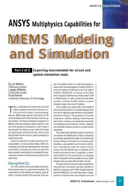
ANSYS Multiphysics Capabilities for<br />
By Jan Mehner,<br />
FEM-ware GmbH<br />
Juergen Wibbeler,<br />
CAD-FEM GmbH<br />
Fouad Bennini<br />
Chemnitz University of Technology<br />
Today, an abundance of commercial circuit <strong>and</strong><br />
system simulation tools exist for electronic circuits<br />
<strong>and</strong> control system virtual prototyping.<br />
However, <strong>MEMS</strong> design engineers still long for an efficient<br />
link between their FEA tool <strong>and</strong> their circuit or system<br />
simulator. The electro-mechanical component of a<br />
<strong>MEMS</strong> is commonly analyzed in detail using FEA. At the<br />
end of this procedure, the question is how to obtain a<br />
macromodel from these accurate results that exhibit<br />
just input/output interface terminals, which can be<br />
directly drawn into the circuit or system schematic by a<br />
simple mouse click.<br />
Numerical methods for model conversion are already<br />
available. In a future product release, ANSYS, Inc.<br />
is working to provide automated generation <strong>and</strong> export<br />
functionality. Concluding this series, we outline the<br />
basic procedure, which leads from a detailed FE microcomponent<br />
model to the desired macromodel for the<br />
system level.<br />
Reducing Model Size<br />
As in FEA, solution accuracy <strong>and</strong> speed critically define<br />
the performance of a system-level simulation. The<br />
requirements for both methods are, however, quite different.<br />
A transient dynamic FEA may be set up for sev-<br />
eral 10-oscillation cycles of a model that typically exceeds<br />
several thous<strong>and</strong> degrees of freedom (DOFs), it<br />
is the norm today for model sizes to be in the range of<br />
10,000 to 100,000 DOF. In contrast, on the system<br />
level, the signal complexity may include several 1,000<br />
to 100,000 cycles. In order to obtain the result within<br />
seconds or minutes, the DOF number in a system<br />
schematic is kept in the order of hundreds.<br />
In the simplest case, lowest-order macromodels of<br />
electro-mechanical parts are manually designed apart<br />
from FEA by rigid-body approximations using lumpedparameter<br />
methods. The parameters of movable<br />
components—stiffness, damping, inertial mass <strong>and</strong><br />
electrostatic coupling—are replaced by equivalent<br />
circuit elements such as inductors, resistors, capacitors<br />
<strong>and</strong> controlled nonlinear sources or by system blocks,<br />
respectively.<br />
The problem with rigid-body models is that they do<br />
not represent the flexible nature of silicon components<br />
as accurately captured by FE models. On the other h<strong>and</strong>,<br />
directly linking an FE-model into a transient system<br />
simulation—as presented in our first series contribution—considerably<br />
slows the system solution<br />
process. The most efficient way is to compress the FE<br />
model size by several orders of magnitude, to write a<br />
macromodel from the reduced data in a language<br />
which is compatible with the available circuit or system<br />
simulator <strong>and</strong> to proceed within the latter one only.<br />
Through substructuring <strong>and</strong> modal superposition,<br />
reduced-order techniques have been available in<br />
ANSYS for a long time, <strong>and</strong> in 1999, through transducer<br />
elements TRANS126. As a novel requirement, the generation<br />
of reduced-order macromodels must link<br />
ANSYS SOLUTIONS<br />
<strong>MEMS</strong> <strong>Modeling</strong><br />
<strong>and</strong> <strong>Simulation</strong><br />
Part 3 of 3: Exporting macromodels for circuit <strong>and</strong><br />
system simulation tools.<br />
ANSYS Solutions www.ansys.com<br />
25
ANSYS Solutions<br />
System simulation with FEA accuracy. The basic procedure to obtain a macromodel based on FE model<br />
data explained at a scanning micromirror example.<br />
26 Volume 3, Number 4 ANSYS Solutions
together the structural, electrostatic <strong>and</strong> fluidic<br />
domains, not to mention nonlinear characteristics.<br />
Shape Function Methods<br />
The deformation state <strong>and</strong> dynamics of mechanical<br />
systems are accurately described by weighted combination<br />
of mode shape functions or modal superposition.<br />
In fact, shape function methods can also be applied to<br />
nonlinear systems. Geometric nonlinearities, for instance,<br />
stress stiffening, can be regarded if the modal<br />
stiffness is computed from the first derivative of the<br />
strain energy function with respect to the modal amplitudes.<br />
Capacitance-stroke functions provide nonlinear<br />
coupling between each eigenmode <strong>and</strong> the electrical<br />
quantities, such as electrostatic modal forces, electrical<br />
current, if stroke is understood as modal amplitude.<br />
Damping parameters are assigned to each eigenmode,<br />
as described in our second series contribution.<br />
Modal representations of <strong>MEMS</strong> are very efficient<br />
since just one equation per mode <strong>and</strong> one equation per<br />
involved conductor are necessary to describe the coupled<br />
system entirely. The approach will be demonstrated<br />
subsequently as the example of our already<br />
known electrostatic scanning micromirror.<br />
Step 1:<br />
Reduction Procedure<br />
The first step of the ROM generation is to determine<br />
which modes are significant <strong>and</strong> to estimate a proper<br />
amplitude range for each mode. Several criteria can be<br />
applied, for instance the lowest eigenmodes of a modal<br />
analysis, modes in operating direction or modes that<br />
contribute to the deflection state at a typical test load.<br />
Applying a unit voltage as test load at one electrode of<br />
the micromirror reveals that its motion is dominated by<br />
the rotational (1), transversal (3), <strong>and</strong> warp (7) eigenmodes.<br />
Next, the dependencies of the strain energy WSENE<br />
<strong>and</strong> of all mutual capacities Cij from the modal amplitudes<br />
are described by polynomial function fits. The<br />
necessary data points are obtained by imposing each<br />
eigenmode with varying amplitude to the mechanical<br />
model for strain energy <strong>and</strong> to an electrostatic space<br />
model for capacitance. Modal damping parameters are<br />
obtained at a fluidic model (shown at left).<br />
Step 2:<br />
Export Macromodel<br />
In the concept of modal superposition, each eigenmode<br />
represents a single independent resonator with<br />
modal mass mi <strong>and</strong> modal damping ci. The system<br />
schematic replaces the resonator’s equation-of-motion<br />
by a simple arrangement of summation, gain <strong>and</strong> integrator<br />
blocks. Polynomials for nonlinear modal excitation<br />
forces <strong>and</strong> stress-stiffness forces are written into<br />
analytical-function blocks.<br />
The structure of this schematic remains constant<br />
for all types of system simulators, <strong>and</strong> therefore, needs<br />
to be exported into a model file using the appropriate<br />
macro language. In the example, the model was generated<br />
for MATLAB/SIMULINK <strong>and</strong> has three voltage<br />
input ports Vi <strong>and</strong> three mechanical output ports carrying<br />
the elongations of eigenmodes 1, 3 <strong>and</strong> 7. A similar<br />
structure is available for network simulators<br />
where the electrical ports carry bidirectional signals,<br />
according to the Kirchhoffian network theory (VHDL-<br />
AMS language).<br />
Step 3:<br />
System <strong>Simulation</strong><br />
Combined with a feedback controller unit, the<br />
micromirror’s rotation shall realize a smooth saw-toothlike<br />
function for scanning image projection. The system<br />
simulation using MATLAB/SIMULINK traces the mirror<br />
motion in the three implemented modes. In practice, the<br />
transversal mode disturbs the electrostatic forces, which<br />
are meant to drive only the rotational mode. The control<br />
loop must provide compensation for those <strong>and</strong> other<br />
disturbances, which is now the objective of circuit prototyping.<br />
Based on the information about the warp<br />
mode, we are able to conclude on the reflection quality<br />
of the mirror.<br />
A rigid-body-based macromodel would only include<br />
the rotational mode, perhaps, with a strong degree of<br />
approximation, the transversal mode, also. Instead, the<br />
reduction of FE data guarantees an accuracy level typical<br />
for FEA at a system analysis speed typical for system <strong>and</strong><br />
circuit simulators.<br />
While our previous two articles discussed coupledfield<br />
methods that are already available within<br />
ANSYS/Multiphysics, this final article casts a view onto<br />
the near future of <strong>MEMS</strong> virtual prototyping. It requires<br />
far more than one single numerical method. The developments<br />
in most organizations <strong>and</strong> engineering companies<br />
are based on various commercial tools for CAD,<br />
FEA, simulation of electronic circuits, control systems,<br />
multibody systems <strong>and</strong> also the microfabrication<br />
processes. Although we are on the forefront of this<br />
progress, many of these tools will be linked together by<br />
appropriate interfaces.<br />
For further information on reduced order modeling<br />
techniques, read J. Mehner, L. Gabbay <strong>and</strong><br />
S.D.Senturia: Computer-aided Generation of Nonlinear<br />
Reducer-Order Dynamic Macromodels, J. Microelectromech.<br />
Syst., Vol. 9, June 2000, pp. 262-278; <strong>and</strong><br />
F. Bennini, J. Mehner, W. Dötzel: Computational Methods<br />
for Reduced-Order <strong>Modeling</strong> of Coupled Domain<br />
<strong>Simulation</strong>s, 11th Int. Conf. On Solid-State Sensors<br />
<strong>and</strong> Actuators, Germany 2001, pp. 260-263.<br />
ANSYS Solutions www.ansys.com<br />
27