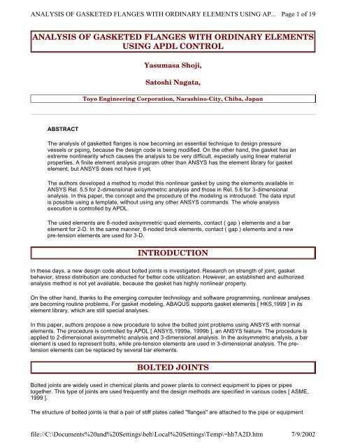
analysis of gasketed flanges with ordinary elements ... - ANSYS Users
analysis of gasketed flanges with ordinary elements ... - ANSYS Users
analysis of gasketed flanges with ordinary elements ... - ANSYS Users

Create successful ePaper yourself
Turn your PDF publications into a flip-book with our unique Google optimized e-Paper software.
ANALYSIS OF GASKETED FLANGES WITH ORDINARY ELEMENTS USING AP...<br />
ANALYSIS OF GASKETED FLANGES WITH ORDINARY ELEMENTS<br />
USING APDL CONTROL<br />
ABSTRACT<br />
Yasumasa Shoji,<br />
Satoshi Nagata,<br />
Toyo Engineering Corporation, Narashino-City, Chiba, Japan<br />
The <strong>analysis</strong> <strong>of</strong> gasketted <strong>flanges</strong> is now becoming an essential technique to design pressure<br />
vessels or piping, because the design code is being modified. On the other hand, the gasket has an<br />
extreme nonlinearity which causes the <strong>analysis</strong> to be very difficult, especially using linear material<br />
properties. A finite element <strong>analysis</strong> program other than <strong>ANSYS</strong> has the element library for gasket<br />
element, but <strong>ANSYS</strong> does not have it yet.<br />
The authors developed a method to model this nonlinear gasket by using the <strong>elements</strong> available in<br />
<strong>ANSYS</strong> Rel. 5.5 for 2-dimensional axisymmetric <strong>analysis</strong> and those in Rel. 5.6 for 3-dimensional<br />
<strong>analysis</strong>. In this paper, the concept and the procedure <strong>of</strong> the modeling is introduced. The data input<br />
is possible using a template, <strong>with</strong>out using any other <strong>ANSYS</strong> commands. The whole <strong>analysis</strong><br />
execution is controlled by APDL.<br />
The used <strong>elements</strong> are 8-noded axisymmetric quad <strong>elements</strong>, contact ( gap ) <strong>elements</strong> and a bar<br />
element for 2-D. In the same manner, 8-noded brick <strong>elements</strong>, contact ( gap ) <strong>elements</strong> and a new<br />
pre-tension <strong>elements</strong> are used for 3-D.<br />
INTRODUCTION<br />
In these days, a new design code about bolted joints is investigated. Research on strength <strong>of</strong> joint, gasket<br />
behavior, stress distribution are conducted for better code utilization. However, an established and authorized<br />
<strong>analysis</strong> method is not yet available, because the gasket has highly nonlinear property.<br />
On the other hand, thanks to the emerging computer technology and s<strong>of</strong>tware programming, nonlinear analyses<br />
are becoming routine problems. For gasket modeling, ABAQUS supports gasket <strong>elements</strong> [ HKS,1999 ] in its<br />
element library, which are still special analyses.<br />
In this paper, authors propose a new procedure to solve the bolted joint problems using <strong>ANSYS</strong> <strong>with</strong> normal<br />
<strong>elements</strong>. The procedure is controlled by APDL [ <strong>ANSYS</strong>,1999a, 1999b ], an <strong>ANSYS</strong> feature. The procedure is<br />
applied to 2-dimensional axisymmetric <strong>analysis</strong> and 3-dimensional <strong>analysis</strong>. In the axisymmetric <strong>analysis</strong>, a bar<br />
element is used to represent bolts, while pre-tension <strong>elements</strong> are used in 3-dimensional <strong>analysis</strong>. The pretension<br />
<strong>elements</strong> can be replaced by several bar <strong>elements</strong>.<br />
BOLTED JOINTS<br />
Page 1 <strong>of</strong> 19<br />
Bolted joints are widely used in chemical plants and power plants to connect equipment to pipes or pipes<br />
together. This type <strong>of</strong> joints are used frequently and the design methods are specified in various codes [ ASME,<br />
1999 ].<br />
The structure <strong>of</strong> bolted joints is that a pair <strong>of</strong> stiff plates called "<strong>flanges</strong>" are attached to the pipe or equipment<br />
file://C:\Documents%20and%20Settings\beh\Local%20Settings\Temp\~hh7A2D.htm<br />
7/9/2002
ANALYSIS OF GASKETED FLANGES WITH ORDINARY ELEMENTS USING AP...<br />
nozzles, sandwich a gasket for fluid seal and clamped by a number <strong>of</strong> bolts and nuts. Sealing performance<br />
depends on how the gasket is compressed [Bickford, 1998 ].<br />
Gasket stresses depend on bolt tension and whether the tension is transferred to the gasket or not is dependent<br />
on the stiffness <strong>of</strong> the <strong>flanges</strong>. Accordingly, the design codes classify <strong>flanges</strong> by service fluids and internal<br />
pressure. The classification is called "rating" and the flange design is carried out according to the rating. Normally<br />
the codes provide standard <strong>flanges</strong> which cover individual ratings. Flange design is now the selection <strong>of</strong> <strong>flanges</strong><br />
from the standard.<br />
The problem <strong>of</strong> this method is that the codes are outdated and they do not predict the real behavior <strong>of</strong> the gaskets<br />
because they were established mainly based on the experiences. Many research have been conducted to<br />
overcome the problem. Especially the highly nonlinear properties <strong>of</strong> gaskets causes difficulty in understanding<br />
gasket behavior.<br />
Thus in the field <strong>of</strong> research <strong>of</strong> bolted joints, many papers deal <strong>with</strong> gasket behavior. Many research are<br />
conducted to know how much load are to be applied to bolts, how scattered the bolt loads are and how the scatter<br />
are to be prevented [ Sawa, 1991, Bouzid, 1999, Shoji,1999 ].<br />
In the following, some issues on gasket nonlinearity is addressed [Fukuoka, 1999 ].<br />
Figure 1 shows a typical stress-strain relation <strong>of</strong> a gasket. The modulus <strong>of</strong> elasticity for bolting-up, or<br />
compression, is quite different from that for internal pressurization <strong>of</strong> the vessel, or decompression <strong>of</strong> the gasket.<br />
The ratio <strong>of</strong> elasticity in decompression to that in compression may exceed 10. When the gasket is<br />
decompressed, it shows strong hysterisis which is remarkably non-linear and causes permanent deformation.<br />
This deformation naturally results that the gasket does not recover the original thickness. In analyzing <strong>gasketed</strong><br />
<strong>flanges</strong>, we must take special care about the status <strong>of</strong> the gasket, either in compression or in decompression, to<br />
choose gasket modulus <strong>of</strong> elasticity and the stress-free thickness.<br />
Figure 1. TYPICAL STRESS-STRAIN RELATION OF GASKET<br />
ANALYSIS METHOD<br />
file://C:\Documents%20and%20Settings\beh\Local%20Settings\Temp\~hh7A2D.htm<br />
Page 2 <strong>of</strong> 19<br />
7/9/2002
ANALYSIS OF GASKETED FLANGES WITH ORDINARY ELEMENTS USING AP...<br />
In this section, method to analyze the bolted joints <strong>with</strong> <strong>ANSYS</strong> is described. Unfortunately, <strong>ANSYS</strong> does not<br />
have gasket <strong>elements</strong>, but has APDL to control <strong>analysis</strong> procedure or <strong>analysis</strong> flow. This APDL enables the<br />
gasket <strong>analysis</strong> procedures <strong>with</strong>out special gasket <strong>elements</strong>.<br />
Analyses are performed for both 2-dimensional axisymmetric models and 3-dimensional models. Axisymmetric<br />
<strong>analysis</strong> was carried out using <strong>ANSYS</strong> release 5.5 and 3-dimensional <strong>analysis</strong> by release 5.6.<br />
Here, although 5.6 provides special pre-tension <strong>elements</strong> which are used in 3-dimensional <strong>analysis</strong>, normal bar<br />
<strong>elements</strong> may be used for modeling <strong>of</strong> bolts. In axisymmetric <strong>analysis</strong> this bar element modeling is employed. In<br />
this bar element modeling, the bolt approximation depends on how high accuracy is needed, whether one bar<br />
may represent one bolt or several bars describe one bolt to accommodate stress distribution in the bolt.<br />
The method for the <strong>analysis</strong> consists <strong>of</strong> basically two phases, which are bolting-up <strong>analysis</strong> and pressurization<br />
<strong>analysis</strong>. First, the <strong>gasketed</strong> <strong>flanges</strong> under the bolting-up condition is analyzed to obtain the initial condition <strong>of</strong> the<br />
<strong>flanges</strong> and gaskets. Next, the <strong>gasketed</strong> <strong>flanges</strong> under pressurized condition is analyzed considering pressure<br />
and hydrostatic end force acting to the shell. In this <strong>analysis</strong>, flange rotation may occur, if the rigidity <strong>of</strong> the <strong>flanges</strong><br />
are not sufficiently large, then non-uniform stress appears on the gasket. If the rotation is rather large, the gasket<br />
detaches from the flange surface at the inner side, or may be more compressed at the outer side. The method<br />
simulates these behaviors <strong>of</strong> the <strong>flanges</strong> and gasket.<br />
Figure 2 shows the overall flow diagram <strong>of</strong> the analytical procedure. Examination <strong>of</strong> the method is described in<br />
the following sections.<br />
In the 3-dimensional model, only half <strong>of</strong> a bolt pitch is modeled considering symmetry, and radial and<br />
circumferencial stress distribution on gasket as well as other parts is calculated. Using these models, analyses in<br />
2-dimension and 3-dimenstion were carried out and compared. The results are described in later sections. For the<br />
3-dimensional <strong>analysis</strong>, the effect <strong>of</strong> bolt holes on the FE model was investigated.<br />
Figure 2. ANALYSIS FLOW<br />
file://C:\Documents%20and%20Settings\beh\Local%20Settings\Temp\~hh7A2D.htm<br />
Page 3 <strong>of</strong> 19<br />
7/9/2002
ANALYSIS OF GASKETED FLANGES WITH ORDINARY ELEMENTS USING AP...<br />
Analysis under initial Bolting-up condition<br />
file://C:\Documents%20and%20Settings\beh\Local%20Settings\Temp\~hh7A2D.htm<br />
Page 4 <strong>of</strong> 19<br />
7/9/2002
ANALYSIS OF GASKETED FLANGES WITH ORDINARY ELEMENTS USING AP...<br />
Bolting-up load is normally given by designer, and currently this is calculated in accordance <strong>with</strong> a design code,<br />
mainly <strong>with</strong> ASME B&PV Code Section VIII Division 1 Appendix 2. Initial strains which are equivalent to the bolt<br />
load for the bar element representing bolts and initial compression <strong>of</strong> the gasket are calculated in this <strong>analysis</strong>.<br />
The analytical models <strong>of</strong> both 2-dimensional axisymmetric and 3-dimensional solid models are shown in Fig. 3<br />
and Fig. 4. These models consist <strong>of</strong> solid <strong>elements</strong> ( PLANE82 for axisymmetric and SOLID185 for 3D ), bar<br />
<strong>elements</strong> ( or initial strain <strong>elements</strong>, LINK1) and gap <strong>elements</strong> ( or contact <strong>elements</strong>, CONTAC12 for<br />
axisymmetric and CONTAC52 for 3D ). As shown in the figures, axisymmetric solid <strong>elements</strong> are used to model<br />
the basic geometry <strong>of</strong> <strong>flanges</strong> and adjacent vessel shell or piping. As mentioned before, bolts are modeled using<br />
a bar element <strong>with</strong> initial strain. The gasket, which is the target <strong>of</strong> this <strong>analysis</strong>, is modeled using gap <strong>elements</strong><br />
which accommodate initial gap and specified stiffness. These gap <strong>elements</strong> are connected to the corresponding<br />
nodes on flange surfaces. Gasket thickness is given by the length <strong>of</strong> the <strong>elements</strong> and it is initially the thickness <strong>of</strong><br />
the virgin gasket. Stiffness <strong>of</strong> the gap <strong>elements</strong> is determined from the stress-strain curve <strong>of</strong> the gasket. Averaged<br />
stiffness is determined by the compression portion from zero deformation to the target deformation which is the<br />
designed thickness after bolting-up. The gasket stiffness, or modulus <strong>of</strong> elasticity, is represented by the slope <strong>of</strong> a<br />
stress-strain curve. The compression gasket stiffness and the decompression one are respectively defined to be<br />
constant which is drawn by dashed-lines in Fig. 1 in this <strong>analysis</strong> method. Here, the slope should be carefully<br />
defined considering the actual thickness change <strong>of</strong> the gasket because the slope affect considerably the result <strong>of</strong><br />
the gasket stress and the distribution.<br />
The gasket stiffness is converted to the spring constants <strong>of</strong> gap <strong>elements</strong> using a simple physics. To obtain the<br />
spring constant, the modulus <strong>of</strong> elasticity is multiplied by the area represented by a single gap element and<br />
divided by the element length ( k = EA/l, where k is spring constant, E is Young’s modulus, A is area and l is<br />
length. ).<br />
The bolt is modeled using a bar element for the axisymmetric models and pre-tension <strong>elements</strong> ( PRETS179 ) for<br />
solid models.<br />
For axisymmetric modeling, as the properties <strong>of</strong> the bar element is based on 360 degrees in <strong>ANSYS</strong>, modulus <strong>of</strong><br />
elasticity and the whole bolt area are input in the model. When this <strong>analysis</strong> is carried out under the initial strain<br />
which is generated by the bar element <strong>of</strong> the bolts, the condition which is in balance among bolt tension, gasket<br />
compression and flange stress must be checked. Then we calculated the appropriate initial strain due to the bolts<br />
from this results. In order to obtain the appropriate initial strain, the model subjected to initial strain <strong>of</strong> unity is<br />
analyzed and the bolt load corresponding to the unity strain is calculated. Initial strain which generates the design<br />
clamping force given by a designer is derived from this <strong>analysis</strong> multiplying the ratio <strong>of</strong> design by the calculated<br />
forces.<br />
In the 3-dimensional <strong>analysis</strong>, it is not necessary to calculate initial strain from the preliminary <strong>analysis</strong>, because<br />
the pre-tension <strong>elements</strong> deal <strong>with</strong> the pre-load and corresponding initial strain. After the pre-load <strong>analysis</strong>, the<br />
calculated initial strain can be used for the <strong>analysis</strong> under pressurized condition. The initial strain calculation was<br />
skipped in the flow chart.<br />
Nuts as well as the bolt are modeled in 3-dimensional <strong>analysis</strong> and the contact between the nut face and the<br />
flange is considered using a contact pair <strong>of</strong> TARGE170 and CONTA173 <strong>with</strong> fully bonded option.<br />
Analysis under the pressurized condition<br />
Page 5 <strong>of</strong> 19<br />
Analysis is carried out in the next step for <strong>gasketed</strong> <strong>flanges</strong> subject to internal pressure <strong>with</strong> the initial strain <strong>of</strong> the<br />
bolt which was derived from the previous <strong>analysis</strong>. In this <strong>analysis</strong>, depending on the stiffness <strong>of</strong> the <strong>flanges</strong><br />
which results in flange rotation, all gasket area may be decompressed or some portion <strong>of</strong> the gasket may be<br />
compressed more while other portion is decompressed. In either cases, the modulus <strong>of</strong> elasticity for the<br />
decompression part in the stress-strain curve is applied for decompressed gasket portion, and the modulus <strong>of</strong> the<br />
compressed part <strong>of</strong> the same curve is used for more-compressed portion <strong>of</strong> the gasket. As it is very difficult to<br />
estimate whether the specific portion <strong>of</strong> the gasket is compressed or decompressed in a deterministic way, the<br />
following iterative approach is applied:<br />
1. Calculate the stress-free length and deformed length <strong>of</strong> each decompressed gasket element from Fig. 1<br />
based on the previous <strong>analysis</strong>.<br />
file://C:\Documents%20and%20Settings\beh\Local%20Settings\Temp\~hh7A2D.htm<br />
7/9/2002
ANALYSIS OF GASKETED FLANGES WITH ORDINARY ELEMENTS USING AP...<br />
2. Assume all the gasket <strong>elements</strong> are decompressed at first.<br />
3. Load internal pressure to the model and analyze it.<br />
4. Check the result. If all the gasket <strong>elements</strong> are decompressed, this iterative method is finished as the<br />
gasket conditions is the same as assumed. If some <strong>elements</strong> are more compressed, change the modulus<br />
<strong>of</strong> elasticity <strong>of</strong> the decompressed by the compressed one, and change the length <strong>of</strong> the gasket by the initial<br />
length ( gasket thickness ). Proceed to the procedure (5) and go on to the next iteration.<br />
5. Load internal pressure to the model and analyze it.<br />
6. Check the result. If the compression/decompression states are the same as the states assumed before<br />
<strong>analysis</strong>, this iterative method is completed. If not, proceed to procedure (7) For example, if the outer two<br />
<strong>elements</strong> are "more-compressed" in the previous <strong>analysis</strong> and so assumed in this <strong>analysis</strong> and only the<br />
two outer <strong>elements</strong> compressed after this <strong>analysis</strong> iteration, the states are considered to be the same and<br />
reasonable. If it is true, the iteration is terminated.<br />
7. Switch the initial condition and material property <strong>of</strong> the <strong>elements</strong> whose compression/decompression<br />
condition is different from their previous iteration, and return to procedure (5). In this procedure, element<br />
lengths calculated in procedure (1) and decompressing modulus <strong>of</strong> elasticity are input for decompressed<br />
<strong>elements</strong>, and the gasket thickness, which is initial length, and compressing modulus <strong>of</strong> elasticity are input<br />
for compressed <strong>elements</strong>.<br />
8. Finally evaluate the results such as flange stress and gasket stress.<br />
When all calculations are completed, reaction force for every gasket element is obtained. These reaction forces<br />
are converted to seat pressure <strong>of</strong> the gasket by dividing the corresponding gasket portion area. If the load is only<br />
internal pressure, all gasket <strong>elements</strong> are decompressed in most cases. This means that computational cost is<br />
much lower than the <strong>analysis</strong> <strong>with</strong> high nonlinear material <strong>elements</strong> such as gasket <strong>elements</strong>.<br />
Figure 3. AXISYMMETRICAL ANALYSIS MODEL<br />
file://C:\Documents%20and%20Settings\beh\Local%20Settings\Temp\~hh7A2D.htm<br />
Page 6 <strong>of</strong> 19<br />
7/9/2002
ANALYSIS OF GASKETED FLANGES WITH ORDINARY ELEMENTS USING AP...<br />
Figure 4. 3-DIMENSIONAL ANALYSIS MODEL<br />
file://C:\Documents%20and%20Settings\beh\Local%20Settings\Temp\~hh7A2D.htm<br />
Page 7 <strong>of</strong> 19<br />
7/9/2002
ANALYSIS OF GASKETED FLANGES WITH ORDINARY ELEMENTS USING AP...<br />
ANALYTICAL OBJECT<br />
The <strong>analysis</strong> was carried out for the standard flange <strong>of</strong> ASME. It is ASME 150 psi rated and 4 inch <strong>of</strong> nominal<br />
outer diameter <strong>with</strong> weld neck ( WN ) and raised face ( RF ). The specification <strong>of</strong> the flange is listed in Table 1.<br />
The material properties used in the <strong>analysis</strong> is on Table 2.<br />
Table 1. SPECIFICATION OF FLANGE<br />
file://C:\Documents%20and%20Settings\beh\Local%20Settings\Temp\~hh7A2D.htm<br />
Page 8 <strong>of</strong> 19<br />
7/9/2002
ANALYSIS OF GASKETED FLANGES WITH ORDINARY ELEMENTS USING AP...<br />
Table 2. MATERIAL PROPERTIES<br />
ANSI 150 lb4B / 4B-SCH40<br />
FLANGE OD 229.0 mm<br />
BORE 102.3 mm<br />
LARGER HUB DIA. 135.0 mm<br />
SMALLER HUB DIA. 114.3 mm<br />
RAISED FACE DIA. 157.0 mm<br />
FLANGE THICKNESS 23.9 mm<br />
RAISED FACE 1.6 mm<br />
FLANGE LENGTH 76.2 mm<br />
BOLT CIRCLE DIA. 190.5 mm<br />
BOLT ROOT DIA. 13.0 mm<br />
NUT DIA. 27.0 mm<br />
NUT THICKNESS 9.5 mm<br />
NO. OF BOLTS 8 nos.<br />
PIPE OD 114.3 mm<br />
PIPE THICKNESS 6.0 mm<br />
BOLT LOAD PER BOLT 13 kN<br />
INTERNAL PRESSURE 1.0 MPa<br />
FLANGE ( SA105 )<br />
MODULUS OF ELASTICITY 200000 MPa<br />
POISSON'S RATIO 0.3<br />
BOLT ( SA193 B7)<br />
MODULUS OF ELASTICITY 200000 MPa<br />
POISSON'S RATIO 0.3<br />
COMPRESSION E C<br />
DECOMPRESSION E D<br />
GASKET<br />
300 MPa<br />
6000 MPa<br />
ANALYSIS RESULTS<br />
2-dimensional Axisymmetric Analysis<br />
Page 9 <strong>of</strong> 19<br />
In this section a result <strong>of</strong> a 2-dimensional axisymmetric <strong>analysis</strong> is presented. The model is shown above ( Fig.<br />
3 ). Stress intensity distribution in pre-loaded condition is shown in Fig. 5, and that in pressurized condition is<br />
shown in Fig. 6. These two figures have the same deformation scale ( /DSCA,,100 ), and flange rotation is<br />
observed larger in pressurized condition. In order to examine the stress distribution <strong>of</strong> the gasket, the gasket<br />
stress results are plotted in Fig. 7. They seem reasonable comparing <strong>with</strong> experiences.<br />
file://C:\Documents%20and%20Settings\beh\Local%20Settings\Temp\~hh7A2D.htm<br />
7/9/2002
ANALYSIS OF GASKETED FLANGES WITH ORDINARY ELEMENTS USING A...<br />
Figure 5. STRESS INTENSITY IN AXISYMMETRIC ANALYSIS UNDER BOLTING-UP CONDITION<br />
Figure 6. STRESS INTENSITY IN AXISYMMETRIC ANALYSIS UNDER PRESSURIZED CONDITION<br />
file://C:\Documents%20and%20Settings\beh\Local%20Settings\Temp\~hh7A2D.htm<br />
Page 10 <strong>of</strong> 19<br />
7/9/2002
ANALYSIS OF GASKETED FLANGES WITH ORDINARY ELEMENTS USING A...<br />
3-dimensional Analysis<br />
In the same manner, a result <strong>of</strong> a 3-dimensional <strong>analysis</strong> is described in this section. The model is shown above<br />
( Fig. 4 ). Stress intensity distribution in pre-loaded condition and in pressurized condition are shown in Fig. 8 and<br />
9, respectively. These two figures have the same deformation scale ( /DSCA,,100 ), and flange rotation is<br />
observed larger in pressurized condition. The gasket stress results are plotted in Fig. 10. They seem reasonable.<br />
Figure 7. GASKET STRESS DISTRIBUTION OBTAINED BY AXISYMMETRIC ANALYSIS<br />
file://C:\Documents%20and%20Settings\beh\Local%20Settings\Temp\~hh7A2D.htm<br />
Page 11 <strong>of</strong> 19<br />
7/9/2002
ANALYSIS OF GASKETED FLANGES WITH ORDINARY ELEMENTS USING A...<br />
Figure 8. STRESS INTENSITY IN 3-DIMENSIONAL ANALYSIS UNDER BOLTING-UP CONDITION<br />
file://C:\Documents%20and%20Settings\beh\Local%20Settings\Temp\~hh7A2D.htm<br />
Page 12 <strong>of</strong> 19<br />
7/9/2002
ANALYSIS OF GASKETED FLANGES WITH ORDINARY ELEMENTS USING A...<br />
Figure 9. STRESS INTENSITY IN 3-DIMENSIONAL ANALYSIS UNDER PRESSURIZED CONDITION<br />
file://C:\Documents%20and%20Settings\beh\Local%20Settings\Temp\~hh7A2D.htm<br />
Page 13 <strong>of</strong> 19<br />
7/9/2002
ANALYSIS OF GASKETED FLANGES WITH ORDINARY ELEMENTS USING A...<br />
Figure 10. GASKET STRESS DISTRIBUTION OBTAINED BY 3-DIMENSIONAL ANALYSIS<br />
file://C:\Documents%20and%20Settings\beh\Local%20Settings\Temp\~hh7A2D.htm<br />
Page 14 <strong>of</strong> 19<br />
7/9/2002
ANALYSIS OF GASKETED FLANGES WITH ORDINARY ELEMENTS USING A...<br />
DISCUSSION<br />
Effect <strong>of</strong> Bolt Holes<br />
In this paper, bolt holes were modeled as they are. However, the modeling <strong>of</strong> holes takes a lot <strong>of</strong> work and it is<br />
questionable whether it is necessary or not in FEA. In FEA, it is not a problem even if bolts are installed through<br />
<strong>flanges</strong> <strong>with</strong>out going through bolt holes. If the stress distribution is the similar in both cases <strong>with</strong> and <strong>with</strong>out bolt<br />
holes, there is no need to model bolt holes. In this section, the effect <strong>of</strong> bolt holes are discussed.<br />
Figure 11. 3-DIMENSIONAL ANALYSIS MODEL WITHOUT BOLT HOLE<br />
file://C:\Documents%20and%20Settings\beh\Local%20Settings\Temp\~hh7A2D.htm<br />
Page 15 <strong>of</strong> 19<br />
7/9/2002
ANALYSIS OF GASKETED FLANGES WITH ORDINARY ELEMENTS USING A...<br />
The result <strong>of</strong> the stress intensity <strong>of</strong> the <strong>flanges</strong> <strong>with</strong>out bolt holes are shown in Fig. 12 under pressurized<br />
condition. Figure 13 shows the comparison <strong>of</strong> the gasket pressure <strong>with</strong> and <strong>with</strong>out bolt holes. It is observed that<br />
both results are nearly the same. It means that bolt holes are not necessary to be modeled in the <strong>analysis</strong>.<br />
Figure 12. STRESS INTENSITY IN 3-DIMENSIONAL ANALYSIS ( WITHOUT BOLT HOLE ) UNDER<br />
PRESSURIZED CONDITION<br />
file://C:\Documents%20and%20Settings\beh\Local%20Settings\Temp\~hh7A2D.htm<br />
Page 16 <strong>of</strong> 19<br />
7/9/2002
ANALYSIS OF GASKETED FLANGES WITH ORDINARY ELEMENTS USING A...<br />
Figure 13. EFFECT OF BOLT HOLE TO GASKET STRESS DISTRIBUTION<br />
file://C:\Documents%20and%20Settings\beh\Local%20Settings\Temp\~hh7A2D.htm<br />
Page 17 <strong>of</strong> 19<br />
7/9/2002
ANALYSIS OF GASKETED FLANGES WITH ORDINARY ELEMENTS USING A...<br />
REFERENCES<br />
1. HKS (Hibbit, Karlsson & Sorensen, Inc.), 1999, ABAQUS/CAE User’s Manual<br />
2. <strong>ANSYS</strong> Inc., 1999a, Analysis Guide ( On Line )<br />
3. <strong>ANSYS</strong> Inc., 1999b, Command Manual ( On Line )<br />
4. ASME (American Society <strong>of</strong> Mechanical Engineers), 1999, Boiler and Pressure Vessel Code Section VIII<br />
Division 1<br />
5. Bickford, 1998, "Gasket and Gasketed Joints", Marcel Dekker Inc.<br />
Page 18 <strong>of</strong> 19<br />
6. Sawa, T., Higurashi, N. and Akagawa, H., 1991, "A stress Analysis <strong>of</strong> Pipe Flange Connections", Journal <strong>of</strong><br />
Pressure Vessel Technology, ASME, Vol. 113, pp 497-503<br />
7. Bouzid, A. and Derenne M., 1999, "A Simple Method for Analyzing the Contact Stress in Bolted Flange<br />
Joints <strong>with</strong> Non-linear Gaskets", Proceedings <strong>of</strong> ASME PVP99, Vol. 382, pp.103-111<br />
8. Shoji, Y. and Nagata S.,1999, "A New Analysis Method for Flange-Gasket Systems" , Proceedings <strong>of</strong><br />
file://C:\Documents%20and%20Settings\beh\Local%20Settings\Temp\~hh7A2D.htm<br />
7/9/2002
ANALYSIS OF GASKETED FLANGES WITH ORDINARY ELEMENTS USING A...<br />
ASME PVP99, Vol. 382, pp.113-120<br />
9. Fukuoka, T. and Takaki, T., 1999, "Evaluations <strong>of</strong> Bolt-up Sequence <strong>of</strong> Pipe Flange Using Three-<br />
Dimensional Finite Element Analysis", Proceedings <strong>of</strong> ASME PVP99, Vol. 382, pp.87-93<br />
file://C:\Documents%20and%20Settings\beh\Local%20Settings\Temp\~hh7A2D.htm<br />
Page 19 <strong>of</strong> 19<br />
7/9/2002