User Manual - Belkin
User Manual - Belkin
User Manual - Belkin

Create successful ePaper yourself
Turn your PDF publications into a flip-book with our unique Google optimized e-Paper software.
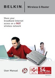
<strong>User</strong> <strong>Manual</strong><br />
802.11g Wireless<br />
Router with Built-In<br />
USB Print Server<br />
<br />
<br />
<br />
<br />
<br />
<br />
F5D7230au4P
Table of Contents<br />
1 Introduction . . . . . . . . . . . . . . . . . . . . . . . . . . . . . . . . . . . . . . . . . . . . 1<br />
Benefits of a Home Network . . . . . . . . . . . . . . . . . . . . . . . . . . . . . . 1<br />
Advantages of a Wireless Network . . . . . . . . . . . . . . . . . . . . . . . . . 1<br />
Placement of your Wireless 802.11g Router . . . . . . . . . . . . . . . . . . 2<br />
2 Product Overview . . . . . . . . . . . . . . . . . . . . . . . . . . . . . . . . . . . . . . . . 6<br />
Product Features . . . . . . . . . . . . . . . . . . . . . . . . . . . . . . . . . . . . . . . 6<br />
3 Knowing your Router . . . . . . . . . . . . . . . . . . . . . . . . . . . . . . . . . . . . . 9<br />
Package Contents . . . . . . . . . . . . . . . . . . . . . . . . . . . . . . . . . . . . . . 9<br />
System Requirements . . . . . . . . . . . . . . . . . . . . . . . . . . . . . . . . . . . 9<br />
Easy Install Wizard Software System Requirements. . . . . . . . . . . . . 9<br />
4 Connecting and Configuring your Router. . . . . . . . . . . . . . . . . . . . . . 14<br />
5 Configuring and Using the USB Print Server . . . . . . . . . . . . . . . . . . . 22<br />
6 Alternate Setup Method . . . . . . . . . . . . . . . . . . . . . . . . . . . . . . . . . . 34<br />
7 Using the Web-Based Advanced <strong>User</strong> Interface . . . . . . . . . . . . . . . . 54<br />
Changing LAN Settings . . . . . . . . . . . . . . . . . . . . . . . . . . . . . . . . . 55<br />
Viewing the DHCP Client List Page . . . . . . . . . . . . . . . . . . . . . . . . 57<br />
Configuring the Wireless Network Settings . . . . . . . . . . . . . . . . . . 58<br />
Securing your Wi-Fi Network . . . . . . . . . . . . . . . . . . . . . . . . . . . . . 63<br />
WEP Setup. . . . . . . . . . . . . . . . . . . . . . . . . . . . . . . . . . . . . . . . 68<br />
WPA Setup . . . . . . . . . . . . . . . . . . . . . . . . . . . . . . . . . . . . . . . . 70<br />
Using the Access Point Mode . . . . . . . . . . . . . . . . . . . . . . . . . . . . 78<br />
Wireless Range Extension and Bridging. . . . . . . . . . . . . . . . . . . . . 79<br />
Configuring the Firewall . . . . . . . . . . . . . . . . . . . . . . . . . . . . . . . . . 83<br />
Setting MAC Address Filtering . . . . . . . . . . . . . . . . . . . . . . . . . . . . 86<br />
Enabling the Demilitarised Zone (DMZ) . . . . . . . . . . . . . . . . . . . . . 87<br />
Utilities Tab . . . . . . . . . . . . . . . . . . . . . . . . . . . . . . . . . . . . . . . . . . 89<br />
Restarting the Router . . . . . . . . . . . . . . . . . . . . . . . . . . . . . . . . 90<br />
Updating the Firmware . . . . . . . . . . . . . . . . . . . . . . . . . . . . . . . 95<br />
8 <strong>Manual</strong>ly Configuring Computer Network Settings . . . . . . . . . . . . . 103<br />
9 Recommended Web Browser Settings . . . . . . . . . . . . . . . . . . . . . . 109<br />
10 Troubleshooting . . . . . . . . . . . . . . . . . . . . . . . . . . . . . . . . . . . . . . 112<br />
11 USB Print Server FAQs . . . . . . . . . . . . . . . . . . . . . . . . . . . . . . . . . 132<br />
12 Information . . . . . . . . . . . . . . . . . . . . . . . . . . . . . . . . . . . . . . . . . . 133
Introduction<br />
Thank you for purchasing the <strong>Belkin</strong> Wireless 802.11g Router (the<br />
Router) with Built-In USB Print Server. Below are two short sections,<br />
one discusses the benefits of home networking, the other outlines<br />
best practices in order to maximise your wireless home network range<br />
and performance. Please be sure to read through this <strong>User</strong> <strong>Manual</strong><br />
completely, and pay special attention to the section entitled “Placement<br />
of your Wireless Networking Hardware for Optimal Performance” on the<br />
next page. By following our simple setup instructions your <strong>Belkin</strong> Home<br />
Network will allow you to:<br />
• Share one high-speed Internet connection with all the computers<br />
in your home<br />
• Share a single printer with the entire family<br />
• Share resources, such as files, and hard drives among all the<br />
connected computers in your home<br />
• Share documents, music, video, and digital pictures<br />
• Store, retrieve, and copy files from one computer to another<br />
• Simultaneously play games online, check Internet e-mail,<br />
and chat<br />
Here are some of the advantages of setting up a<br />
<strong>Belkin</strong> Wireless Network:<br />
Mobility – you’ll no longer need a dedicated “computer room”— now<br />
you can work on a networked laptop or desktop computer from virtually<br />
anywhere within your wireless range<br />
Easy installation – <strong>Belkin</strong>’s Easy Installation Wizard makes setup simple<br />
Flexibility – set up and access printers, computers, and other<br />
networking devices from anywhere in your home<br />
Easy Expansion – the wide range of <strong>Belkin</strong> networking products let<br />
you expand your network to include devices such as printers and<br />
gaming consoles<br />
No cabling required – you can spare the expense and hassle of<br />
retrofitting Ethernet cabling throughout the home or office<br />
Widespread industry acceptance – choose from a wide range of<br />
interoperable networking products<br />
1<br />
1<br />
2<br />
3<br />
4<br />
5<br />
6<br />
7<br />
8<br />
9<br />
10<br />
11<br />
12<br />
section
Introduction<br />
Placement of your Wireless 802.11g Router<br />
Important Factors for Placement and Setup<br />
Your wireless connection will be stronger the closer your computer<br />
is to your Wireless Router or Access Point. Typical indoor operating<br />
range for your wireless devices is between 100 and 200 feet. In the<br />
same way, your wireless connection and performance will degrade<br />
somewhat as the distance between your Wireless Router or Access<br />
Point and connected devices increases. This may or may not be<br />
noticeable to you. As you move further from your Wireless Router<br />
or Access Point, connection speed may decrease. Factors that can<br />
weaken signals simply by getting in the way of your network’s radio<br />
waves are metal appliances or obstructions, and walls.<br />
If you have concerns about your network’s performance that might be<br />
related to range or obstruction factors, try moving the computer to a<br />
position between five and ten feet from the Wireless Router or Access<br />
Point, in order to see if distance is the problem. If difficulties persist<br />
even at close range, please contact <strong>Belkin</strong> Technical Support.<br />
Note: While some of the items listed below can affect network<br />
performance, they will not prohibit your wireless network from<br />
functioning; if you are concerned that your network is not operating at<br />
its maximum effectiveness, this checklist may help.<br />
1. Wireless Router or Access Point Placement<br />
Place your Wireless Router or Access Point, the central<br />
connection point of your network, as close as possible to the<br />
centre of your wireless network devices.<br />
To achieve the best wireless network coverage for your “wireless<br />
clients” (i.e., computers enabled by <strong>Belkin</strong> Wireless Notebook<br />
Network Cards, Wireless Desktop Network Cards, and Wireless<br />
USB Adapters):<br />
• Ensure that your Wireless Router’s or Access Point’s<br />
networking antennas are parallel to each other, and are<br />
positioned vertically (toward the ceiling). If your Wireless<br />
Router or Access Point itself is positioned vertically, point the<br />
antennas as much as possible in an upward direction.<br />
• In multistory homes, place the Wireless Router or Access<br />
Point on a floor that is as close to the centre of the home as<br />
possible. This may mean placing the Wireless Router or Access<br />
Point on an upper floor.<br />
• Try not to place the Wireless Router or Access Point near a<br />
cordless 2.4GHz phone.<br />
2
Introduction<br />
2. Avoid Obstacles and Interference<br />
Avoid placing your Wireless Router or Access Point near<br />
devices that may emit radio “noise,” such as microwave ovens.<br />
Dense objects that can inhibit Wireless communication include:<br />
• Refrigerators<br />
• Washers and/or dryers<br />
• Metal cabinets<br />
• Large aquariums<br />
• Metallic-based UV tinted windows<br />
If your wireless signal seems weak in some spots, make sure that<br />
objects such as these are not blocking the signal’s path (between<br />
your computers and Wireless Router or Access Point).<br />
3. Cordless Phones<br />
If the performance of your wireless network is impaired after<br />
attending to the above issues, and you have a cordless phone:<br />
• Try moving cordless phones away from Wireless Routers or<br />
Access Points and your wireless-enabled computers<br />
• Unplug and remove the battery from any cordless phone<br />
that operate on the 2.4GHz band (check manufacturers<br />
information). If this fixes the problem, your phone may<br />
be interfering.<br />
• If your phone supports channel selection, change the<br />
channel on the phone to the furthest channel from your<br />
wireless network. For example, change the phone to channel 1<br />
and move your Wireless Router or Access Point to channel 11.<br />
See your phone’s user manual for detailed instructions.<br />
• If necessary, consider switching to a 900MHz or 5GHz<br />
cordless phone.<br />
4. Choose the “quietest” channel for your wireless network<br />
In locations where homes or offices are close together, such as<br />
apartment buildings or office complexes, there may be wireless<br />
networks nearby that can conflict with yours.<br />
Use the Site Survey capabilities found in the Wireless LAN Utility<br />
of your wireless adapter to locate any other wireless networks that<br />
are available (see your wireless adapter’s manual), and move your<br />
Wireless Router (or Access Point) and computers to a channel as<br />
far away from other networks as possible.<br />
3<br />
1<br />
2<br />
3<br />
4<br />
5<br />
6<br />
7<br />
8<br />
9<br />
10<br />
11<br />
12<br />
section
Introduction<br />
Experiment with more than one of the available channels, in<br />
order to find the clearest connection and avoid interference from<br />
neighbouring cordless phones or other wireless devices.<br />
For <strong>Belkin</strong> wireless networking products, use the detailed Site<br />
Survey and wireless channel information included in your<br />
<strong>User</strong> Guide.<br />
These guidelines should allow you to cover the maximum<br />
possible area with your Wireless Router or Access Point. Should<br />
you need to cover an even wider area, we suggest the <strong>Belkin</strong><br />
Wireless Range Extender/Access Point.<br />
5. Secure connections and VPNs<br />
Secure connections are connections that typically require a user<br />
name and password, and are used where security is important.<br />
Secure connections include:<br />
• Virtual Private Network (VPN) connections, often used to<br />
connect remotely to an office network<br />
• Most on-line banking websites<br />
• Many commercial websites which require a username and<br />
password to access your account<br />
Secure connections can be interrupted by a computer’s power<br />
management setting, which causes it to “go to sleep.” The<br />
simplest solution to avoid this is to simply reconnect by<br />
re-running the VPN software, or by re-logging into<br />
the secure web site.<br />
A second alternative is to change your computer’s power<br />
management settings so it does not go to sleep; however, this may<br />
not be appropriate for portable computers. To change your power<br />
management setting under Windows, see the “Power Options” item in<br />
the Control Panel.<br />
If you continue to have difficulty with Secure Connection or VPNs<br />
please review the steps above to be sure you have addressed these<br />
issues.<br />
4
Introduction<br />
For more information regarding our networking products, visit our website<br />
at www.belkin.com/networking or call <strong>Belkin</strong> Technical Support at:<br />
US: 877-736-5771<br />
310-898-1100 ext.2263<br />
Europe: 00 800 223 55 460<br />
Australia: 1800 235 546<br />
New Zealand: 0800 235 546<br />
5<br />
1<br />
2<br />
3<br />
4<br />
5<br />
6<br />
7<br />
8<br />
9<br />
10<br />
11<br />
12<br />
section
Product Overview<br />
Product Features<br />
In minutes you will be able to share your Internet connection and<br />
network your computers. The following is a list of features that<br />
make your new <strong>Belkin</strong> Wireless 802.11g Router an ideal solution for<br />
your home or small office network.<br />
Works with Both PCs and Mac ® Computers<br />
The Router supports a variety of networking environments including<br />
Mac OS ® 8.x, 9.x, X v10.x, AppleTalk ® , Linux ® , Windows ® 95, 98,<br />
Me, NT ® , 2000, and XP, and others. All that is needed is an Internet<br />
browser and a network adapter that supports TCP/IP (the standard<br />
language of the Internet).<br />
Front-Panel LED Display<br />
LEDs on the front of the Router indicate which functions are in<br />
operation. You’ll know at-a-glance whether your Router is connected<br />
to the Internet. This feature eliminates the need for advanced software<br />
and status-monitoring procedures.<br />
Built-in USB Print Server<br />
Your router includes a built-in USB print server that lets you print to<br />
a USB printer from any computer on the network. The print server<br />
is very simple to setup and convenient to use. Simply install your<br />
printer’s drivers and software on each computer, and then run the<br />
easy to use Print Server Setup Wizard to setup the print server. In<br />
minutes, all of your computers will have access to the same printer.<br />
NAT IP Address Sharing<br />
Your Router employs Network Address Translation (NAT) to share the<br />
single IP address assigned to you by your Internet Service Provider<br />
while saving the cost of adding additional IP addresses to your<br />
Internet service account.<br />
6
Product Overview<br />
SPI Firewall<br />
Your Router is equipped with a firewall that will protect your network<br />
from a wide array of common hacker attacks including IP Spoofing,<br />
Land Attack, Ping of Death (PoD), Denial of Service (DoS), IP with<br />
zero length, Smurf Attack, TCP Null Scan, SYN flood, UDP flooding,<br />
Tear Drop Attack, ICMP defect, RIP defect, and fragment flooding.<br />
Integrated 10/100 4-Port Switch<br />
The Router has a built-in, 4-port network switch to allow your wired<br />
computers to share printers, data and MP3 files, digital photos,<br />
and much more. The switch features automatic detection so it will<br />
adjust to the speed of connected devices. The switch will transfer<br />
data between computers and the Internet simultaneously without<br />
interrupting or consuming resources.<br />
Universal Plug-and-Play (UPnP) Compatibility<br />
UPnP (Universal Plug-and-Play) is a technology that offers seamless<br />
operation of voice messaging, video messaging, games, and other<br />
applications that are UPnP-compliant.<br />
Support for VPN Pass-Through<br />
If you connect to your office network from home using a VPN<br />
connection, your Router will allow your VPN-equipped computer to<br />
pass through the Router and to your office network.<br />
Built-In Dynamic Host Configuration Protocol (DHCP)<br />
Built-In Dynamic Host Configuration Protocol (DHCP) on-board makes<br />
for the easiest possible connection of a network. The DHCP server<br />
will assign IP addresses to each computer automatically so there is<br />
no need for a complicated networking setup.<br />
Easy Install Wizard<br />
The Easy Install Wizard takes the guesswork out of setting up your<br />
Router. This automatic software determines your network settings for<br />
you and sets up the Router for connection to your Internet Service<br />
Provider (ISP). In a matter of minutes, your Wireless Router will be up and<br />
running on the Internet. A separate wizard is included for setup of the print<br />
server.<br />
7<br />
1<br />
2<br />
3<br />
4<br />
5<br />
6<br />
7<br />
8<br />
9<br />
10<br />
11<br />
12<br />
section
Product Knowing Overview Your Router<br />
NOTE: Easy Install Wizard software is compatible with Windows 98SE, Me,<br />
2000, XP and Mac OS 9.X and Mac OS X. The Print Server Setup Wizard<br />
software is compatible with Windows 98SE, Me, 2000, and XP. If you are<br />
using another operating system, the Wireless Router can be set up using the<br />
Alternative Method described in this manual (see page 34).<br />
Integrated 802.11g Wireless Access Point<br />
802.11g is an exciting new wireless technology that achieves data rates up to<br />
54Mbps in 54G Mode, nearly five times faster than 802.11b.<br />
Integrated Parental Control Web Content Filter<br />
<strong>Belkin</strong> has teamed with Cerberian, a leading content-filtering company, to<br />
bring you this unique feature. Your <strong>Belkin</strong> Wireless 802.11g Router is the first<br />
home networking solution with an integrated web content filter that allows<br />
you to block unwanted or offensive web content before it makes it to your<br />
network. Unlike other Parental Control solutions, Parental Control is built into<br />
the <strong>Belkin</strong> Wireless Router, so there is no software to install on any computer<br />
and you will never be charged a per-computer fee for the service, ever. Your<br />
Wireless Router comes with a six-month free trial of this feature so you can<br />
take advantage of the capabilities right away. No credit card is needed to use<br />
the trial. You have control: <strong>Belkin</strong> Parental Control can be modified to meet<br />
your needs. You can set up your own policies and block any website you<br />
want. There is also an optional reporting feature (fee-based) that allows you<br />
to get a report showing you every website that was visited from your network<br />
(refer to your Parental Control <strong>Manual</strong> for more information).<br />
MAC Address Filtering<br />
For added security, you can set up a list of MAC addresses (unique client<br />
identifiers) that are allowed access to your network. Every computer has its<br />
own MAC address. Simply enter these MAC addresses into a list using the<br />
web-based user interface and you can control access to your network.<br />
8
Knowing Your Router<br />
Package Contents<br />
• <strong>Belkin</strong> Wireless 802.11g Router with Built-In USB<br />
Print Server<br />
• Quick Installation Guide<br />
• <strong>Belkin</strong> Easy Install Wizard Software CD<br />
• <strong>Belkin</strong> RJ45 Ethernet Networking Cable<br />
• Power Supply<br />
• <strong>User</strong> <strong>Manual</strong><br />
System Requirements<br />
• Broadband Internet connection such as a cable or DSL modem with<br />
RJ45 (Ethernet) connection<br />
• At least one computer with an installed network interface adapter<br />
• TCP/IP networking protocol installed on each computer<br />
• RJ45 Ethernet networking cable<br />
• Internet browser<br />
Easy Install Wizard Software System Requirements<br />
• A PC running Windows 98SE, Me, 2000, or XP<br />
• Minimum 64MB RAM<br />
• Internet Browser<br />
Print Server Setup Wizard System Requirements<br />
• A PC running Windows 98SE, Me, 2000, or XP<br />
• Minimum 64MB RAM<br />
9<br />
1<br />
2<br />
3<br />
4<br />
5<br />
6<br />
7<br />
8<br />
9<br />
10<br />
11<br />
12<br />
section
Knowing Your Router<br />
The Router has been designed to be placed on a desktop. All of the<br />
cables exit from the rear of the Router for better organization and<br />
utility. The LED indicators are easily visible on the front of the Router<br />
to provide you with information about network activity and status.<br />
(1) (2) (3) (4) (5)<br />
2.4GHz • High-Speed Wireless G<br />
1. Power/Ready/Print Activity LED<br />
When you apply power to the Router or restart it, a short period<br />
of time elapses while the Router boots up. During this time, the<br />
LED blinks. When the Router has completely booted up, the<br />
Power/Ready LED becomes a SOLID light, indicating the Router<br />
is ready for use. When data is being sent to the printer, the light<br />
will blink fast.<br />
OFF Router is OFF<br />
Slow Blinking Router is Booting Up<br />
Solid Router is Ready<br />
Fast Blinking Green Printer Activity<br />
2. WLAN: Wireless Network LED<br />
OFF Wireless Network is OFF<br />
Solid Wireless Network is Ready<br />
Blinking Indicates Wireless Activity<br />
3. LAN Port-Status LEDs<br />
These LEDs are labeled 1–4 and correspond to the numbered<br />
ports on the rear of the Router. When a computer is properly<br />
connected to one of the LAN ports on the rear of the Router, the<br />
LED will light. GREEN means a 10Base-T device is connected,<br />
ORANGE means a 100Base-T device is connected. When<br />
information is being sent over the port, the LED blinks rapidly.<br />
10
Knowing Your Router<br />
OFF No Device is Linked to the Port<br />
Green 10Base-T Device Connected<br />
Orange 100Base-Tx Device Connected<br />
Blinking<br />
(Orange or Green)<br />
Port Activity<br />
4. WAN Status LED<br />
This LED lights SOLID to indicate that your modem is connected<br />
properly to the Router. It blinks rapidly when information is being<br />
sent over the port between the Router and the modem.<br />
OFF No WAN Link<br />
Solid Good WAN Link<br />
Blinking WAN Activity<br />
5. Connected LED<br />
This unique LED shows you when the Router is connected to the<br />
Internet. When the light is OFF, the Router is NOT connected to<br />
the Internet. When the light is blinking, the Router is attempting<br />
to connect to the Internet. When the light is SOLID, the Router<br />
is connected to the Internet. When using the “Disconnect<br />
after x minutes” feature, this LED becomes extremely useful in<br />
monitoring the status of your Router’s connection.<br />
OFF Router is not Connected to the Internet<br />
Blinking Router is Attempting to Connect to the<br />
Internet<br />
Solid Router is Connected to the Internet<br />
11<br />
1<br />
2<br />
3<br />
4<br />
5<br />
6<br />
7<br />
8<br />
9<br />
10<br />
11<br />
12<br />
section
Knowing Your Router<br />
(6) (7) (8) (9)(10)<br />
6. Power Jack - GREY<br />
Connect the included 5V DC power supply to this jack.<br />
7. Connections to Computers (LAN Ports) - BLUE<br />
Connect your wired (non-wireless) computers to these ports.<br />
These ports are RJ45, 10/100 auto-negotiation, auto-uplinking<br />
ports for standard UTP category 5 or 6 Ethernet cable. The ports<br />
are labeled 1 through 4. These ports correspond to the numbered<br />
LEDs on the front of the Router.<br />
8. Connection to Modem (WAN Port) - GREEN<br />
This port is for connection to your cable or DSL modem. Use the<br />
cable that was provided with the modem to connect the modem<br />
to this port. Use of a cable other than the cable supplied with the<br />
cable modem may not work properly.<br />
9. Reset Button<br />
The Reset button is used in rare cases when the Router may<br />
function improperly. Resetting the Router will restore the Router’s<br />
normal operation while maintaining the programmed settings. You<br />
can also restore the factory default settings by using the Reset<br />
button. Use the restore option in instances where you may have<br />
forgotten your custom password.<br />
a. Resetting the Router<br />
Push and release the Reset button. The lights on the Router<br />
will momentarily flash. The Power/Ready light will begin to<br />
blink. When the Power/Ready light becomes solid again, the<br />
reset is complete.<br />
12
Knowing Your Router<br />
b. Restoring the Factory Defaults<br />
Press and hold the Reset button for at least ten seconds<br />
then release it. The lights on the Router will momentarily<br />
flash. The Power/Ready light will begin to blink. When the<br />
Power/Ready light becomes solid again, the restore<br />
is complete.<br />
10. USB Port - PURPLE<br />
For USB printers only. See the section called “Connecting your<br />
printer to Router’s print server” on page 22.<br />
13<br />
1<br />
2<br />
3<br />
4<br />
5<br />
6<br />
7<br />
8<br />
9<br />
10<br />
11<br />
12<br />
section
Connecting and Configuring Your Router<br />
Verify the contents of your box. You should have the following:<br />
• <strong>Belkin</strong> Wireless 802.11g Router<br />
• Quick Installation Guide<br />
• <strong>Belkin</strong> Easy Install Wizard Software CD<br />
• RJ45 Ethernet Networking Cable (for connection of the<br />
Router to the computer)<br />
• Power Supply<br />
• <strong>User</strong> <strong>Manual</strong><br />
Modem Requirements<br />
Your cable or DSL modem must be equipped with an RJ45 Ethernet<br />
port. Many modems have both an RJ45 Ethernet port and a USB<br />
connection. If you have a modem with both Ethernet and USB, and<br />
are using the USB connection at this time, you will be instructed to<br />
use the RJ45 Ethernet port during the installation procedure. If your<br />
modem has only a USB port, you can request a different type of<br />
modem from your ISP, or you can, in some cases, purchase a modem<br />
that has an RJ45 Ethernet port on it.<br />
Ethernet USB<br />
ALWAYS INSTALL YOUR ROUTER FIRST! IF YOU ARE INSTALLING<br />
NUMEROUS NETWORK DEVICES FOR THE FIRST TIME, IT IS<br />
IMPORTANT THAT YOUR ROUTER IS CONNECTED AND RUNNING<br />
BEFORE ATTEMPTING TO INSTALL OTHER NETWORK COMPONENTS<br />
SUCH AS NOTEBOOK CARDS AND DESKTOP CARDS.<br />
Easy Install Wizard<br />
<strong>Belkin</strong> has provided our Easy Install Wizard software to make<br />
installing your Router a simple and easy task. You can use it to get<br />
your Router up and running in minutes.<br />
The Easy Install Wizard requires that your Windows® 98SE, Me,<br />
2000, XP or Mac OS 9.2x, X.1.x computer be connected directly to<br />
your cable or DSL modem and that the Internet connection is active<br />
14
Connecting and Configuring Your Router<br />
and working at the time of installation. If it is not, you must use the<br />
“Alternate Setup Method” section of this manual to configure your<br />
Router. Additionally, if you are using an operating system other than<br />
Windows 98SE, Me, 2000, or XP, you must set up the Router using<br />
the “Alternate Setup Method” section of this manual.<br />
IMPORTANT: Run the Easy Install Wizard software from the<br />
computer that is directly connected to the cable or DSL modem.<br />
DO NOT CONNECT THE ROUTER AT THIS TIME.<br />
Step 1 Run the Easy Install Wizard Software<br />
1. Shut down any programs that are running on your computer at<br />
this time.<br />
2. Make sure you have the following items at the computer that is<br />
now directly connected to the cable or DSL modem. DO NOT<br />
CONNECT THE ROUTER AT THIS TIME.<br />
• Quick Installation Guide<br />
• The Easy Install Wizard CD-ROM<br />
• The Router<br />
• The Router power supply<br />
• RJ45 Ethernet networking cable<br />
• This <strong>User</strong> <strong>Manual</strong><br />
3. Turn off any firewall or Internet connection sharing software on<br />
your computer.<br />
4. Insert the Easy Install Wizard software CD into your CD–ROM<br />
drive. The Installation Menu will automatically appear on your<br />
screen within 15 seconds. If it does not, select your CD-ROM<br />
drive from “My Computer” and double-click on the file named<br />
“Start.exe” on the CD-ROM.<br />
15<br />
1<br />
2<br />
3<br />
4<br />
5<br />
6<br />
7<br />
8<br />
9<br />
10<br />
11<br />
12<br />
section
Connecting and Configuring Your Router<br />
5. Click “Run Router Setup Wizard”.<br />
Region Screen<br />
The Region screen will appear. Select your<br />
region from the dropdown box provided<br />
and click “OK”.<br />
Welcome Screen<br />
The Wizard’s welcome screen will<br />
appear. Make sure you have not<br />
connected the Router at this point. If<br />
you have connected your Router, please<br />
reconnect your computer directly to<br />
the modem. Click “Next” when you are<br />
ready to move on.<br />
16
Connecting and Configuring Your Router<br />
Connection Screen<br />
The Connection screen will now appear.<br />
Select the scenario that best describes<br />
your current ADSL setup and click “Next”.<br />
Progress Screen<br />
Easy Install will show you a progress<br />
screen each time a step in the setup<br />
has been completed. Each time you see<br />
the progress screen, click “Next” when<br />
you are ready to move to the next step.<br />
Examining Settings<br />
The Wizard will now examine your<br />
computer’s network settings and gather<br />
information needed to complete the<br />
Router’s connection to the Internet.<br />
When the Wizard is finished examining<br />
your computer, click “Next” to continue.<br />
Multi-NICs Screen<br />
If you have more than one network adapter installed in your computer<br />
a Multi-NIC Screen will appear. If you have more than one network<br />
adapter installed in your computer, the Wizard will need to know<br />
which adapter is connected to your modem. Select the network card<br />
that is connected to your modem from the list and click “Next”. If you<br />
are not sure which adapter to choose, select the adapter at the top of<br />
the list. If you mistakenly choose the wrong adapter now, you will be<br />
able to choose a different one later.<br />
17<br />
1<br />
2<br />
3<br />
4<br />
5<br />
6<br />
7<br />
8<br />
9<br />
10<br />
11<br />
12<br />
section
Connecting and Configuring Your Router<br />
Step 2 Hardware Setup<br />
The Wizard will walk you through connecting your Router to your<br />
computer and modem. Follow the steps on the screen using the<br />
pictures as a guide.<br />
2.1 This step instructs you to locate<br />
the cable connected between your<br />
modem and the networking port on<br />
your computer. Unplug this cable<br />
from the computer and plug it into<br />
the GREEN port on the Router.<br />
Click “Next” to continue.<br />
2.2 This step instructs you to locate<br />
the BLUE cable that is included<br />
with your Router. Plug one end<br />
of this cable into ANY one of the<br />
BLUE ports on your Router. Plug<br />
the other end of the cable into the<br />
networking port on your computer.<br />
Click “Next” to continue.<br />
2.3 This step instructs you to locate<br />
the power supply that is included<br />
with your Router. Plug the power<br />
supply’s small connector into the<br />
GREY port on the Router. Plug the<br />
power supply into an empty power<br />
outlet. Click “Next” to continue.<br />
18
Connecting and Configuring Your Router<br />
Step 3 Checking the Connection<br />
2.4 This step instructs you to look<br />
at the lights on the front of your<br />
Router. Make sure the appropriate<br />
lights are ON. Refer to the Easy<br />
Install software on your computer’s<br />
screen for more details. Click<br />
“Next” to continue.<br />
3.1 Once you have completed<br />
connecting the Router, the Wizard<br />
will check the connection to the<br />
Router and then go on to determine<br />
what type of Internet connection<br />
you have.<br />
3.2 <strong>User</strong> Name and Password Needed<br />
If you have a connection type that<br />
requires a user name and a password,<br />
the Wizard will ask you to type in<br />
your user name and password. If your<br />
connection type does not require a<br />
user name and password, you will not<br />
see this screen.<br />
Your user name and password is provided to you by your Internet Service<br />
Provider. If you have to type in a user name and password to connect to<br />
the Internet, then type that same user name and password in here. Your<br />
user name looks something like “jsmith@myisp.com” or simply “jsmith”.<br />
The service name is optional and is very rarely required by your ISP. If you<br />
don’t know your service name, leave this blank. When you have entered<br />
your information, click “Next” to move on.<br />
19<br />
1<br />
2<br />
3<br />
4<br />
5<br />
6<br />
7<br />
8<br />
9<br />
10<br />
11<br />
12<br />
section
Connecting and Configuring Your Router<br />
Step 4 Configuring the Router<br />
3.3 Wireless Setup<br />
This Step Is Optional. Click “Next” if<br />
you want to skip it.<br />
20<br />
Using this step, you can customise<br />
your wireless network settings if<br />
you want to. Follow the steps on<br />
the screen to complete this step.<br />
Click “Next” to continue.<br />
The Wizard will now transfer all of the configuration information to the<br />
Router. This will take approximately one minute. During this time, do<br />
not turn off the Router or computer. The Router will restart itself at the<br />
end of this step.<br />
4.1 Checking Internet<br />
The Wizard will now check for an<br />
Internet connection. This can take<br />
a few minutes. The Wizard may not<br />
detect a connection right away. If<br />
not, it will retry a number of times.<br />
The “Connected” light on the front<br />
panel of the Router will flash during<br />
this time. Please be patient through<br />
this process.
Connecting and Configuring Your Router<br />
4.2 Finished<br />
When the Internet connection<br />
is complete, the Wizard will tell<br />
you that you are finished. The<br />
“Connected” LED on the front of<br />
the Router will be SOLID, indicating<br />
that the Router is now connected<br />
to the Internet.<br />
Your Router is now connected to the Internet. Now you can begin<br />
surfing the Internet by opening your browser and going to your favorite<br />
web page.<br />
Congratulations! You have finished installing your new <strong>Belkin</strong> Router.<br />
You are ready to set up the other computers in your home. You can<br />
also add computers to your Router any time you want.<br />
21<br />
1<br />
2<br />
3<br />
4<br />
5<br />
6<br />
7<br />
8<br />
9<br />
10<br />
11<br />
12<br />
section
Configuring and Using the USB Print Server<br />
Connecting your printer to the Router’s print server<br />
Please closely follow the directions to set up your printer.<br />
Before you start<br />
Install the printer’s drivers and software on each computer from which you<br />
plan to print. This enables the PC to print to the networked printer (printer<br />
that is attached to your USB Print Server). Every manufacturer ships its<br />
printer with a driver and, usually, printing software. In some cases, while<br />
installing the drivers and software for your printer, you may be required to<br />
connect the PC directly to the printer in order to complete the installation.<br />
This varies according to manufacturer. You must also install the <strong>Belkin</strong> Printer<br />
Port on each of the computers you want to print from. This may be done<br />
using the Printer Server Setup Wizard, or can be done manually.<br />
Start<br />
1. Insert the CD into your CD-ROM drive. Within 15 seconds, you<br />
should see the installation menu on the screen. If the menu<br />
does not appear within 15 seconds, select your CD-ROM drive<br />
and view the contents of the drive. Double-click on the file<br />
named “Start.exe”.<br />
2. From the menu, click on “Run Print Server Setup Wizard”. This<br />
will open the Print Server Setup Wizard menu.<br />
22
Configuring and Using the USB Print Server<br />
3. On the Wizard menu, drag your mouse over the “Run Wizard”<br />
button and click the words “Click Here” to start the Wizard.<br />
4. The first screen of the Wizard appears. Be sure that you have<br />
installed your printer’s drivers and software on the PCs from<br />
which you plan to print. Click “Next”.<br />
23<br />
1<br />
2<br />
3<br />
4<br />
5<br />
6<br />
7<br />
8<br />
9<br />
10<br />
11<br />
12<br />
section
Configuring and Using the USB Print Server<br />
5. Next, make sure the Router is ON. Make sure the printer is ON.<br />
Plug in the USB cable that is connected to the printer to the USB<br />
port on the rear of the Router. The USB port on the Router is<br />
color-coded purple. Click “Next”.<br />
6. The Wizard will scan for and locate the Print Server in the Router.<br />
Next, a list of the printers installed on the computer will appear.<br />
Click once on the name of the printer that is connected to the<br />
Router to highlight it. Click “Next”.<br />
24
Configuring and Using the USB Print Server<br />
7. The next screen that appears will allow you to test print. Click<br />
on the “Print Test Page” button. When your test page is finished<br />
printing, click “Next”.<br />
8. You are now finished setting up your computer to print to the<br />
Print Server. Next, run this Wizard on the other computers on<br />
your network from which you wish to print to this printer.<br />
25<br />
1<br />
2<br />
3<br />
4<br />
5<br />
6<br />
7<br />
8<br />
9<br />
10<br />
11<br />
12<br />
section
Configuring and Using the USB Print Server<br />
<strong>Manual</strong>ly installing the print server port<br />
Advanced users can manually install the <strong>Belkin</strong> Printer Port without using the<br />
Wizard. To do this, from the Installer menu, click “Install Printer Port Only” to<br />
skip the Wizard. <strong>Belkin</strong> has also included a standalone installer on the CD.<br />
From the CD, double-click on the file called “instportA.exe”.<br />
Configuring Computers to Print to the Print Server<br />
1. Install Printer Port Software on each computer by running<br />
“instportA.exe” from the CD or by using the Wizard.<br />
2. Configure the <strong>Belkin</strong> Port Monitor on each computer’s printer<br />
driver to point to the Router’s Print Server as follows:<br />
a. In Windows, select the printer’s properties for the printer<br />
connected to the Print Server and select the “Port” tab,<br />
select the <strong>Belkin</strong> port, and click “Configure Port...”<br />
b. On the “<strong>Belkin</strong> PortA: Properties” window, click “Locate Servers”.<br />
26
Configuring and Using the USB Print Server<br />
c. On the “Available Servers” window, your Router’s print server<br />
name will appear. Select the Print Server. Click “OK” to close.<br />
d. On the “<strong>Belkin</strong> Port A: Properties” window, the name of the<br />
Print Server will appear. Click “OK” to close.<br />
e. On the Ports tab, uncheck the box next to “Enable bidirectional<br />
support” if currently checked. Click “Apply”.<br />
f. Click “Close” to close the window.<br />
27<br />
1<br />
2<br />
3<br />
4<br />
5<br />
6<br />
7<br />
8<br />
9<br />
10<br />
11<br />
12<br />
section
Configuring and Using the USB Print Server<br />
Uninstalling the print server port<br />
1. In Windows, select the printer’s properties for the printer connected to<br />
the Print Server and select the “Port” tab, select the <strong>Belkin</strong> port, and click<br />
“Configure Port...”.<br />
2. Select a different port from the list of available ports. You must select a<br />
different port before you can remove the <strong>Belkin</strong> port.<br />
3. From the Installer menu, click “Remove Printer Port” to uninstall the<br />
printer port. <strong>Belkin</strong> has also provided an uninstaller application that will<br />
remove the <strong>Belkin</strong> printer port from the PC. From the CD, double-click on<br />
the file called “rmvportA.exe”. This will remove the printer port.<br />
28
Configuring and Using the USB Print Server<br />
Using the Print Server<br />
Print Server Configuration Screen<br />
For proper operation of the Print Server, install the printer’s drivers and<br />
software on each computer from which you plan to print. The <strong>Belkin</strong> Print<br />
Server Port must also be installed on each of these computers. See page 26<br />
of this manual for more information and instructions.<br />
The Print Server Configuration screen is the central point in the Router where<br />
you can find the printer status (ready/not ready) and make certain adjustments.<br />
See page 52 in this manual for directions to access the Advanced Web Based<br />
<strong>User</strong> Interface.<br />
(1)<br />
(2)<br />
(3)<br />
(4)<br />
(5)<br />
Printer field (1)<br />
This line shows you the name of the printer that is connected to the Print<br />
Server and its status.<br />
Print Server Name (2)<br />
The Print Server name identifies the Print Server. If you wish, you can<br />
change it by typing in a new name such as “My Print Server” then clicking<br />
“Apply Changes”.<br />
29<br />
1<br />
2<br />
3<br />
4<br />
5<br />
6<br />
7<br />
8<br />
9<br />
10<br />
11<br />
12<br />
section
Configuring and Using the USB Print Server<br />
LPR Printing (3)<br />
The <strong>Belkin</strong> Printer Port uses LPR as the main printing method.<br />
Raw TCP/IP Printing (4)<br />
This feature allows clients to print to the Print Server using the standard TCP/IP printer<br />
port built into Windows XP and 2000, instead of the <strong>Belkin</strong> Port Monitor. Using Raw<br />
Printing requires that you configure all port parameters manually. It is not recommended<br />
for users unfamiliar with TCP/IP printing.<br />
FTP Printing (5)<br />
This feature enables the printer to receive print jobs sent by FTP (see “Using FTP Printing”<br />
on this page). Disabling this feature will prevent FTP jobs from printing<br />
Using FTP Printing<br />
This section describes how to send print jobs to the printer using FTP.<br />
1. In Windows, select the printer’s properties.<br />
30
Configuring and Using the USB Print Server<br />
2. Set the printer port to “File”, click “Apply”.<br />
3. Print the document using the printer that you configured. A<br />
dialogue box will open prompting you to name the print file.<br />
After naming the file, click “OK”. A file will be saved to the user’s<br />
default Windows directory (typically “C:\” or “C:\Documents and<br />
Settings\”).<br />
31<br />
1<br />
2<br />
3<br />
4<br />
5<br />
6<br />
7<br />
8<br />
9<br />
10<br />
11<br />
12<br />
section
Configuring and Using the USB Print Server<br />
4. On the Windows desktop, click “Start>Run” and type in “cmd” for<br />
Windows XP and 2000 or “command” for Windows 98SE and Me;<br />
click “OK” to open a “Command/MS-DOS Prompt” window.<br />
5. At the prompt, type “ftp” followed by the IP address of the Router<br />
(default is 192.168.2.1); press the “Enter” key to create an FTP<br />
connection with the Print Server.<br />
6. When the connection is made, the user will be prompted to<br />
enter a user name and a password. The user name for the Print<br />
Server is “anonymous”; the password should be left blank. After<br />
a successful login, a list of the printers connected to the Print<br />
Server will appear, followed by simple usage instructions for how<br />
to print the file.<br />
32
Configuring and Using the USB Print Server<br />
7. At the prompt, type “put”, followed by the file path and file<br />
name, followed by the printer number (for example, “put c:\<br />
example printer1”).<br />
8. The file will be sent to the Print Server. When the transfer is<br />
complete, another prompt will appear. If finished, type “quit” and<br />
press “Enter” to end the FTP session. Then, close the “Command<br />
Prompt” window.<br />
Note: FTP Printing by default is enabled in the Print Server. It can be<br />
disabled using the Router’s Web-Based Setup Interface. See page 29<br />
for details.<br />
33<br />
1<br />
2<br />
3<br />
4<br />
5<br />
6<br />
7<br />
8<br />
9<br />
10<br />
11<br />
12<br />
section
Alternate Setup Method<br />
The Advanced <strong>User</strong> Interface is a web-based tool that you can use to<br />
set up the Router if you don’t want to use the Easy Install Wizard. You<br />
can also use it to manage advanced functions of the Router. From the<br />
Advanced <strong>User</strong> Interface, you can perform the following tasks:<br />
• View the Router’s current settings and status.<br />
• Configure the Router to connect to your ISP with the settings that<br />
they provided you.<br />
• Change the current network settings such as the Internal IP<br />
address, the IP address pool, DHCP settings and more.<br />
• Set the Router’s firewall to work with specific applications<br />
(port forwarding).<br />
• Set up security features such as client restrictions, MAC address<br />
filtering, WEP and WPA.<br />
• Enable the DMZ feature for a single computer on your network.<br />
• Change the Router’s internal password.<br />
• Enable/Disable UPnP (Universal Plug-and-Play).<br />
• Reset the Router.<br />
• Back up your configuration settings.<br />
• Reset the Router’s default settings.<br />
• Update the Router’s firmware.<br />
Step 1 Connecting your Router<br />
1.1 Turn off the power to your modem by unplugging the power<br />
supply from the modem.<br />
1.2 Locate the network cable that is connected between your modem<br />
and your computer and unplug it from your computer, leaving the<br />
other end connected to your modem.<br />
1.3 Plug the loose end of the cable you just unplugged into the green<br />
port on the back of the Router labeled “Connection to Modem”.<br />
1.4 Connect the new blue network cable (included) from the back of<br />
the computer to one of the blue ports labeled “1–4”. Note: It does<br />
not matter which numbered port you choose.<br />
34
Alternate Setup Method<br />
1.5 Turn your cable or DSL modem on by reconnecting the power<br />
supply to the modem.<br />
Mac or PC computer that was originally<br />
connected to the cable or DSL modem<br />
Network cable<br />
(to computer)<br />
To Power Adapter<br />
35<br />
Existing networking cable<br />
(came with modem)<br />
Note: Your Router may have ports in different locations than<br />
depicted in the illustration above.<br />
1.6 Before plugging the power cord into the Router, plug the cord<br />
into the wall, then plug the cord into the Router’s power jack.<br />
1.7 Verify that your modem is connected to the Router by checking<br />
the lights on the front of the Router. The light labeled “WAN”<br />
should be ON if your modem is connected correctly to the<br />
Router. If it is not, recheck your connections.<br />
1.8 Verify that your computer is connected properly to the Router<br />
by checking the lights labeled “LAN 1,2,3,4”. The light which<br />
corresponds to the numbered port connected to your computer<br />
should be ON, if your computer is connected properly. If it is not,<br />
recheck your connections.<br />
1<br />
2<br />
3<br />
4<br />
5<br />
6<br />
7<br />
8<br />
9<br />
10<br />
11<br />
12<br />
section
Alternate Setup Method<br />
Step 2 Set your Computer’s Network Settings to Work<br />
with a DHCP Server<br />
See the section in this manual called “<strong>Manual</strong>ly Configuring Network<br />
Settings” for directions.<br />
Step 3 Configuring the Router Using the Web-Based<br />
Advanced <strong>User</strong> Interface<br />
Using your Internet browser, you can access the Router’s Web-Based<br />
Advanced <strong>User</strong> Interface. In your browser, type “192.168.2.1” (you do<br />
not need to type in anything else such as “http://” or “www”). Then<br />
press the “Enter” key.<br />
PLEASE NOTE: If you have difficulty accessing the Router’s webbased<br />
interface, go to Section 7 of the user manual titled “<strong>Manual</strong>ly<br />
Configuring Computer Network Settings”.<br />
Logging into the Router<br />
You will see the Router’s home page in your browser window. The<br />
home page is visible to any user who wants to see it. To make any<br />
changes to the Router’s settings, you have to log in. Clicking the<br />
“Login” button or clicking on any one of the links on the home page<br />
will take you to the login screen. The Router ships with no password<br />
entered. In the login screen, leave the password blank and click the<br />
“Submit” button to log in.<br />
36
Alternate Setup Method<br />
Logging out of the Router<br />
One computer at a time can log in to the Router for the purposes<br />
of making changes to the settings of the Router. Once a user has<br />
logged in to make changes, there are two ways that the computer<br />
can be logged out. Clicking the “Logout” button will log the computer<br />
out. The second method is automatic. The login will time out after a<br />
specified period of time. The default login time out is 10 minutes. This<br />
can be changed from 1 to 99 minutes. For more information, see the<br />
section in this manual titled “Changing the Login Timeout Setting”.<br />
Understanding the Web-Based Advanced <strong>User</strong> Interface<br />
The home page is the first page you will see when you access the<br />
Advanced <strong>User</strong> Interface (UI). The home page shows you a quick view<br />
of the Router’s status and settings. All advanced setup pages can be<br />
reached from this page.<br />
(1)<br />
(10) (2) (5) (4) (3)<br />
(9) (8)<br />
1. Quick-Navigation Links<br />
You can go directly to any of the Router’s advanced UI pages by<br />
clicking directly on these links. The links are divided into logical<br />
categories and grouped by tabs to make finding a particular<br />
setting easier to find. Clicking on the purple header of each tab<br />
will show you a short description of the tab’s function.<br />
37<br />
(7)<br />
(6)<br />
1<br />
2<br />
3<br />
4<br />
5<br />
6<br />
7<br />
8<br />
9<br />
10<br />
11<br />
12<br />
section
Alternate Setup Method<br />
(1)<br />
(10) (2) (5) (4) (3)<br />
(9) (8)<br />
2. Home Button<br />
The home button is available in every page of the UI. Pressing<br />
this button will take you back to the home page.<br />
3. Internet Status Indicator<br />
This indicator is visible in all pages of the Router, indicating<br />
the connection status of the Router. When the indicator says<br />
“connection OK” in GREEN, the Router is connected to the<br />
Internet. When the Router is not connected to the Internet, the<br />
indicator will read “no connection” in RED. The indicator is<br />
automatically updated when you make changes to the settings of<br />
the Router.<br />
4. Login/Logout Button<br />
This button enables you to log in and out of the Router with the<br />
press of one button. When you are logged into the Router, this<br />
button will change to read “Logout”. Logging into the Router will<br />
take you to a separate login page where you will need to enter a<br />
password. When you are logged in to the Router, you can make<br />
changes to the settings. When you are finished making changes,<br />
you can log out of the Router by clicking the “Logout” button. For<br />
more information about logging into the Router, see the section<br />
called “Logging into the Router”.<br />
38<br />
(7)<br />
(6)
Alternate Setup Method<br />
5. Help Button<br />
The “Help” button gives you access to the Router’s help pages.<br />
Help is also available on many pages by clicking “more info” next<br />
to certain sections of each page.<br />
6. LAN Settings<br />
Shows you the settings of the Local Area Network (LAN) side of<br />
the Router. Changes can be made to the settings by clicking on<br />
any one of the links (IP Address, Subnet Mask, DHCP Server) or<br />
by clicking the “LAN” Quick Navigation link on the left side of<br />
the screen.<br />
7. Features<br />
Shows the status of the Router’s NAT, firewall, and wireless<br />
features. Changes can be made to the settings by clicking on any<br />
one of the links or by clicking the “Quick Navigation” links on the<br />
left side of the screen.<br />
8. Internet Settings<br />
Shows the settings of the Internet/WAN side of the Router that<br />
connects to the Internet. Changes to any of these settings can<br />
be made by clicking on the links or by clicking on the “Internet/<br />
WAN” Quick Navigation link on the left side of the screen.<br />
9. Version Info<br />
Shows the firmware version, boot-code version, hardware<br />
version, and serial number of the Router.<br />
10. Page Name<br />
The page you are on can be identified by this name. This manual<br />
will sometimes refer to pages by name. For instance “LAN > LAN<br />
Settings” refers to the “LAN Settings” page.<br />
39<br />
1<br />
2<br />
3<br />
4<br />
5<br />
6<br />
7<br />
8<br />
9<br />
10<br />
11<br />
12<br />
section
Alternate Setup Method<br />
Step 4 Configuring your Router for Connection to your Internet<br />
Service Provider (ISP)<br />
The “Internet/WAN” tab is where you will set up your Router to<br />
connect to your Internet Service Provider (ISP). The Router is capable<br />
of connecting to virtually any ISP’s system provided you have<br />
correctly configured the Router’s settings for your ISP’s connection<br />
type. Your ISP connection settings are provided to you by your ISP.<br />
To configure the Router with the settings that your ISP gave you,<br />
click “Connection Type” (A) on the left side of the screen. Select<br />
the connection type you use. If your ISP gave you DNS settings,<br />
clicking “DNS” (B) allows you to enter DNS address entries for ISPs<br />
that require specific settings. Clicking “MAC address” (C) will let you<br />
clone your computer’s MAC address or type in a specific WAN MAC<br />
address, if required by your ISP. When you have finished making<br />
settings, the “Internet Status” indicator will read “connection OK” if<br />
your Router is set up properly.<br />
(A)<br />
(B)<br />
(C)<br />
40
(1)<br />
Alternate Setup Method<br />
Setting your Connection Type<br />
From the connection type page, you can select the type of connection you<br />
use. Select the type of connection you use by clicking the button (1) next<br />
to your connection type and then clicking “Next” (2).<br />
41<br />
(2)<br />
1<br />
2<br />
3<br />
4<br />
5<br />
6<br />
7<br />
8<br />
9<br />
10<br />
11<br />
12<br />
section
Alternate Setup Method<br />
Setting your Internet Service Provider (ISP) Connection Type<br />
to Dynamic IP<br />
A dynamic connection type is the most common connection type<br />
found with cable modems. Setting the connection type to “dynamic”<br />
in many cases is enough to complete the connection to your ISP.<br />
Some dynamic connection types may require a host name. You can<br />
enter your host name in the space provided if you were assigned one.<br />
Your host name is assigned by your ISP. Some dynamic connections<br />
may require that you clone the MAC address of the PC that was<br />
originally connected to the modem.<br />
(1)<br />
(2)<br />
1. Host Name<br />
This space is provided to enter a host name that needs to be<br />
visible to your ISP. Enter your host name here and click “Apply<br />
Changes” (3). If your ISP did not assign you a host name, or you<br />
are not sure, leave this blank.<br />
2. Change WAN MAC Address<br />
If your ISP requires a specific MAC address to connect to the<br />
service, you can enter a specific MAC address or clone the<br />
current computer’s MAC address through this link.<br />
42<br />
(3)
Alternate Setup Method<br />
Setting your Internet Service Provider (ISP) Connection Type<br />
to Static IP<br />
A static IP address connection type is less common than other connection<br />
types. If your ISP uses static IP addressing, you will need your IP address,<br />
subnet mask, and ISP gateway address. This information is available from<br />
your ISP or on the paperwork that your ISP left with you. Type in your<br />
information, then click “Apply Changes” (5). After you apply the changes,<br />
the Internet Status indicator will read “connection OK” if your Router is set<br />
up properly.<br />
(1)<br />
(2)<br />
(3)<br />
(4)<br />
43<br />
(5)<br />
1. IP Address<br />
Provided by your ISP. Enter your IP address here.<br />
2. Subnet Mask<br />
Provided by your ISP. Enter your subnet mask here.<br />
3. ISP Gateway Address<br />
Provided by your ISP. Enter the ISP gateway address here.<br />
4. My ISP Provides More Than One Static IP Address<br />
If your ISP assigns you more than one static IP address, your<br />
Router is capable of handling up to five static WAN IP addresses.<br />
Select “My ISP provides more than one static IP address” and<br />
enter your additional addresses.<br />
1<br />
2<br />
3<br />
4<br />
5<br />
6<br />
7<br />
8<br />
9<br />
10<br />
11<br />
12<br />
section
(1)<br />
(2)<br />
(3)<br />
(4)<br />
(5)<br />
Alternate Setup Method<br />
Setting your ISP connection type to PPPoE<br />
Most DSL providers use PPPoE as the connection type. If you use a<br />
DSL modem to connect to the Internet, your ISP may use PPPoE to<br />
log you into the service. If you have an Internet connection in your<br />
home or small office that doesn’t require a modem, you may also use<br />
PPPoE.<br />
Your connection type is PPPoE if:<br />
a) Your ISP gave you a user name and password which is required to<br />
connect to the Internet<br />
b) Your ISP gave you software such as WinPOET or Enternet300 that<br />
you use to connect to the Internet<br />
or<br />
c) You have to double-click on a desktop Icon other than your<br />
browser to get on the Internet<br />
44<br />
(6)
Alternate Setup Method<br />
1. <strong>User</strong> Name<br />
This space is provided to type in your <strong>User</strong> name that was<br />
assigned by your ISP.<br />
2. Password<br />
Type in your password and re-type it into the “Retype Password”<br />
box to confirm it.<br />
3. Service Name<br />
A Service name is rarely required by an ISP. If you are not sure if<br />
your ISP requires a service name, leave this blank.<br />
4. MTU<br />
The MTU setting should never be changed unless your ISP gives<br />
you a specific MTU setting. Making changes to the MTU setting<br />
can cause problems with your Internet connection including<br />
disconnection from the Internet, slow Internet access and<br />
problems with Internet applications working properly.<br />
5. Disconnect after X...<br />
The Disconnect feature is used to automatically disconnect the<br />
router from your ISP when there is no activity for a specified<br />
period of time. For instance, placing a checkmark next to this<br />
option and entering 5 into the minute field will cause the router<br />
to disconnect from the Internet after 5 minutes of no Internet<br />
activity. This option should be used if you pay for your Internet<br />
service by the minute.<br />
45<br />
1<br />
2<br />
3<br />
4<br />
5<br />
6<br />
7<br />
8<br />
9<br />
10<br />
11<br />
12<br />
section
Alternate Setup Method<br />
Setting your Internet Service Provider (ISP) Connection Type to<br />
Point-to-Point Tunneling Protocol (PPTP)<br />
[European Countries Only]. Some ISPs require a connection using<br />
PPTP protocol, a type of connection most common in European<br />
countries. This sets up a direct connection to the ISP’s system. Type<br />
in the information provided by your ISP in the space provided. When<br />
you have finished, click “Apply Changes” (9). After you apply the<br />
changes, the Internet Status indicator will read “connection OK” if<br />
your Router is set up properly.<br />
(1)<br />
(2)<br />
(3)<br />
(4)<br />
(5)<br />
(6)<br />
(7)<br />
(8)<br />
1. PPTP Account<br />
Provided by your ISP. Enter your PPTP account name here.<br />
2. PPTP Password<br />
Type in your password and retype it into the “Retype Password”<br />
box to confirm it.<br />
3. Host Name<br />
Provided by your ISP. Enter your host name here.<br />
46<br />
(9)
Alternate Setup Method<br />
4. Service IP Address<br />
Provided by your ISP. Enter your service IP address here.<br />
5. My IP Address<br />
Provided by your ISP. Enter the IP address here.<br />
6. My Subnet Mask<br />
Provided by your ISP. Enter the IP address here.<br />
7. Connection ID (optional)<br />
Provided by your ISP. If your ISP did not give you a connection<br />
ID, leave this blank.<br />
8. Disconnect after X….<br />
The Disconnect feature is used to automatically disconnect the<br />
Router from your ISP when there is no activity for a specified<br />
period of time. For instance, placing a check mark next to this<br />
option and entering “5” into the minute field will cause the Router<br />
to disconnect from the Internet after five minutes of no Internet<br />
activity. This option should be used if you pay for your Internet<br />
service by the minute.<br />
47<br />
1<br />
2<br />
3<br />
4<br />
5<br />
6<br />
7<br />
8<br />
9<br />
10<br />
11<br />
12<br />
section
Alternate Setup Method<br />
Setting your Connection Type if you are a Telstra ® BigPond Cable <strong>User</strong><br />
[Australia Only] Your user name and password are provided to you by<br />
Telstra BigPond. Enter this information below.<br />
Note: Your user name should be the same as your email address,<br />
but with the “@bigpond.com” part removed.<br />
Your password should be the same as the password you use<br />
for your BigPond email account.<br />
Choosing your state from the drop-down menu (1) will automatically<br />
fill in your login server IP address. If your login server address is<br />
different than one provided here, you may manually enter the login<br />
server IP address by placing a check in the box next to “<strong>User</strong> decide<br />
login server manually” (4) and type in the address next to “Login<br />
Server” (5). When you have entered all of your information, click<br />
“Apply Changes” (7). After you apply the changes, the Internet Status<br />
indicator will read “connection OK” if your Router is set up properly.<br />
(1)<br />
(2)<br />
(3)<br />
(4)<br />
(5)<br />
Note: You may have to turn your modem off for 20-40 minutes to allow<br />
any active BigPond connections to disconnect from BigPond servers.<br />
48<br />
(7)
Alternate Setup Method<br />
1. Select your State<br />
Select your state from the drop-down menu (1). The “Login<br />
Server” box will automatically be filled in with an IP address.<br />
If for some reason this address does not match the address<br />
that Telstra has given, you can manually enter the login server<br />
address. See “<strong>User</strong> Decide Login Server <strong>Manual</strong>ly” (4).<br />
2. <strong>User</strong> Name<br />
Provided by your ISP. Type in your user name here (this should<br />
be the same as your email address, but with the “@bigpond.com”<br />
part removed).<br />
3. Password<br />
Type in your password and retype it into the “Retype Password”<br />
box to confirm it (this should be the same as the password you<br />
use for your BigPond email account).<br />
4. <strong>User</strong> Decide Login Server <strong>Manual</strong>ly<br />
If your login server IP address is not available in the “Select Your<br />
State” drop-down menu (1), you may manually enter the login<br />
server IP address by placing a check in the box next to “<strong>User</strong><br />
decide login server manually” and type in the address next to<br />
“Login Server” (5).<br />
49<br />
1<br />
2<br />
3<br />
4<br />
5<br />
6<br />
7<br />
8<br />
9<br />
10<br />
11<br />
12<br />
section
Alternate Setup Method<br />
Setting Custom Domain Name Server (DNS) Settings<br />
A “Domain Name Server” is a server located on the Internet that<br />
translates Universal Resource Locator (URLs) like “www.belkin.com”<br />
to IP addresses. Many Internet Service Providers (ISPs) do not require<br />
you to enter this information into the Router. The “Automatic from ISP”<br />
box (1) should be checked if your ISP did not give you a specific DNS<br />
address. If you are using a static IP connection type, then you may<br />
need to enter a specific DNS address and secondary DNS address for<br />
your connection to work properly. If your connection type is dynamic<br />
or PPPoE, it is likely that you do not have to enter a DNS address.<br />
Leave the “Automatic from ISP” box checked. To enter the DNS address<br />
settings, uncheck the “Automatic from ISP” box and enter your DNS<br />
entries in the spaces provided. Click “Apply Changes” (2) to save<br />
the settings.<br />
(1)<br />
50<br />
(2)
Alternate Setup Method<br />
Configuring your WAN Media Access Controller<br />
(MAC) Address<br />
All network components including cards, adapters, and routers, have<br />
a unique “serial number” called a MAC address. Your Internet Service<br />
Provider may record the MAC address of your computer’s adapter and<br />
only let that particular computer connect to the Internet service. When<br />
you install the Router, its own MAC address will be “seen” by the<br />
ISP and may cause the connection not to work. <strong>Belkin</strong> has provided<br />
the ability to clone (copy) the MAC address of the computer into the<br />
Router. This MAC address, in turn, will be seen by the ISP’s system as<br />
the original MAC address and will allow the connection to work. If you<br />
are not sure whether your ISP needs to see the original MAC address,<br />
simply clone the MAC address of the computer that was originally<br />
connected to the modem. Cloning the address will not cause any<br />
problems with your network.<br />
Note: In some cases we have seen that BigPond Cable users have<br />
had to clone the MAC address of the Network Card of the PC with the<br />
BigPond software installed.<br />
If you have installed the <strong>Belkin</strong> router in place of an old router which<br />
was connected to your BigPond service, you will need to clone the MAC<br />
address of this router’s WAN port (the unit’s MAC address is normally<br />
found on the underside of your router, or on its config page).<br />
Please refer to the manufacturer’s user manual on how to find this<br />
information.<br />
51<br />
1<br />
2<br />
3<br />
4<br />
5<br />
6<br />
7<br />
8<br />
9<br />
10<br />
11<br />
12<br />
section
Alternate Setup Method<br />
Cloning your MAC Address<br />
To clone your MAC address, make sure that you are using the<br />
computer that was ORIGINALLY CONNECTED to your modem before<br />
the Router was installed. Click the “Clone” button (1). Click “Apply<br />
Changes” (3). Your MAC address is now cloned to the Router.<br />
Entering a Specific MAC Address<br />
In certain circumstances you may need a specific WAN MAC address.<br />
You can manually enter one in the “MAC Address” page. Type in a<br />
MAC address in the spaces provided (2) and click “Apply Changes” (3)<br />
to save the changes. The Router’s WAN MAC address will now be<br />
changed to the MAC address you specified.<br />
52<br />
(2)<br />
(1)<br />
(3)
Alternate Setup Method<br />
53<br />
1<br />
2<br />
3<br />
4<br />
5<br />
6<br />
7<br />
8<br />
9<br />
10<br />
11<br />
12<br />
section
Using the Web-Based Advanced <strong>User</strong> Interface<br />
Using your Internet browser, you can access the Router’s Web-Based<br />
Advanced <strong>User</strong> Interface. In your browser, type “192.168.2.1” (do<br />
not type in anything else such as “http://” or “www”) then press the<br />
“Enter” key.<br />
You will see the Router’s home page in your browser window.<br />
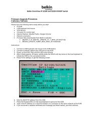
Viewing the LAN Settings<br />
Clicking on the header of the LAN tab (1) will take you to the LAN<br />
tab’s header page. A quick description of the functions can be<br />
found here. To view the settings or make changes to any of the LAN<br />
settings, click on “LAN Settings” (2) or to view the list of connected<br />
computers, click on “DHCP Client List” (3).<br />
(1)<br />
(2)<br />
(3)<br />
54
Using the Web-Based Advanced <strong>User</strong> Interface<br />
Changing LAN Settings<br />
All settings for the internal LAN setup of the Router can be viewed<br />
and changed here.<br />
(1)<br />
(2)<br />
(3)<br />
(4)<br />
(5)<br />
(6)<br />
1. IP Address<br />
The “IP address” is the internal IP address of the Router. The<br />
default IP address is “192.168.2.1”. To access the advanced<br />
setup interface, type this IP address into the address bar of your<br />
browser. This address can be changed if needed. To change the<br />
IP address, type in the new IP address and click “Apply Changes”.<br />
The IP address you choose should be a non-routable IP.<br />
Examples of a non-routable IP are:<br />
192.168.x.x (where x is anything between 0 and 255)<br />
10.x.x.x (where x is anything between 0 and 255)<br />
2. Subnet Mask<br />
There is no need to change the subnet mask. This is a unique,<br />
advanced feature of your <strong>Belkin</strong> Router. It is possible to change<br />
the subnet mask if necessary, however, do NOT make changes to<br />
the subnet mask unless you have a specific reason to do so. The<br />
default setting is “255.255.255.0”.<br />
55<br />
1<br />
2<br />
3<br />
4<br />
5<br />
6<br />
7<br />
8<br />
9<br />
10<br />
11<br />
12<br />
section
Using the Web-Based Advanced <strong>User</strong> Interface<br />
3. DHCP Server<br />
The DHCP server function makes setting up a network very easy<br />
by assigning IP addresses to each computer on the network<br />
automatically. The default setting is “On”. The DHCP server<br />
can be turned OFF if necessary, however, in order to do so you<br />
must manually set a static IP address for each computer on<br />
your network. To turn off the DHCP server, select “Off” and click<br />
“Apply Changes”.<br />
4. IP Pool<br />
The range of IP addresses set aside for dynamic assignment to the<br />
computers on your network. The default is 2–100 (99 computers). If<br />
you want to change this number, you can do so by entering a new<br />
starting and ending IP address and clicking on “Apply Changes”.<br />
The DHCP server can assign 100 IP addresses automatically. This<br />
means that you cannot specify an IP address pool larger than 100<br />
computers. For example, starting at 50 means you have to end at<br />
150 or lower so as not to exceed the 100-client limit. The starting<br />
IP address must be lower in number than the ending IP address.<br />
5. Lease Time<br />
The length of time the DHCP server will reserve the IP address<br />
for each computer. We recommend that you leave the lease<br />
time set to “Forever”. The default setting is “Forever”, meaning<br />
that any time a computer is assigned an IP address by the<br />
DHCP server, the IP address will not change for that particular<br />
computer. Setting lease times for shorter intervals such as one<br />
day or one hour frees IP addresses after the specified period of<br />
time. This also means that a particular computer’s IP address<br />
may change over time. If you have set any of the other advanced<br />
features of the Router such as DMZ or client IP filters, these are<br />
dependent on the IP address. For this reason, you will not want<br />
the IP address to change.<br />
6. Local Domain Name<br />
The default setting is “<strong>Belkin</strong>”. You can set a local domain name<br />
(network name) for your network. There is no need to change this<br />
setting unless you have a specific advanced need to do so. You can<br />
name the network anything you want such as “MY NETWORK”.<br />
56
Using the Web-Based Advanced <strong>User</strong> Interface<br />
Viewing the DHCP Client List Page<br />
You can view a list of the computers (known as clients), which are<br />
connected to your network. You are able to view the IP address (1) of<br />
the computer, the host name (2) (if the computer has been assigned<br />
one), and the MAC address (3) of the computer’s network interface<br />
card (NIC). Pressing the “Refresh” button will update the list. If there<br />
have been any changes, the list will be updated.<br />
(1) (2) (3)<br />
57<br />
1<br />
2<br />
3<br />
4<br />
5<br />
6<br />
7<br />
8<br />
9<br />
10<br />
11<br />
12<br />
section
Using the Web-Based Advanced <strong>User</strong> Interface<br />
Configuring the Wireless Network Settings<br />
The Wireless tab lets you make changes to the wireless network<br />
settings. From this tab you can make changes to the wireless network<br />
name (SSID), operating channel, encryption security settings, and<br />
configure the Router to be used as an access point.<br />
Changing the Wireless Network Name (SSID)<br />
To identify your wireless network, a name called the SSID (Service<br />
Set Identifier) is used. The default SSID of the Router is “belkin54g”.<br />
You can change this to anything you want to or you can leave it<br />
unchanged. If there are other wireless networks operating in your<br />
area, you will want to make sure that your SSID is unique (does not<br />
match that of another wireless network in the area). To change the<br />
SSID, type in the SSID that you want to use in the SSID field (1) and<br />
click “Apply Changes” (2). The change is immediate. If you make a<br />
change to the SSID, your wireless-equipped computers may also need<br />
to be reconfigured to connect to your new network name. Refer to the<br />
documentation of your wireless network adapter for information on<br />
making this change.<br />
58<br />
(1)<br />
(2)
Using the Web-Based Advanced <strong>User</strong> Interface<br />
Using the Wireless Mode Switch<br />
Your Router can operate in three different wireless modes: “802.11g-<br />
Auto”, “802.11g-Only”, and “802.11g-LRS”. The different modes are<br />
explained below.<br />
802.11g-Auto Mode<br />
In this mode, the Router is compatible with 802.11b and 802.11g<br />
wireless clients simultaneously. This is the factory default mode and<br />
ensures successful operation with all Wi-Fi-compatible devices. If<br />
you have a mix of 802.11b and 802.11g clients in your network, we<br />
recommend setting the Router to 802.11g-Auto mode. This setting<br />
should only be changed if you have a specific reason to do so.<br />
802.11g-Only Mode<br />
802.11g-Only mode works with 802.11g clients only. This mode<br />
is recommended only if you want to prevent 802.11b clients from<br />
accessing your network. To switch modes, select the desired<br />
mode from the “Wireless Mode” drop-down box. Then, click<br />
“Apply Changes”.<br />
802.11g-LRS Mode<br />
We recommend you DO NOT use this mode unless you have a very<br />
specific reason to do so. This mode exists only to solve unique<br />
problems that may occur with some 802.11b client adapters and is<br />
NOT necessary for interoperability of 802.11g and 802.11b standards.<br />
When to Use 802.11g-LRS Mode<br />
In some cases, older 802.11b clients may not be compatible with<br />
802.11g wireless. These adapters tend to be of inferior design and<br />
may use older drivers or technology. 802.11g-LRS (Limited Rate<br />
Support) allows these clients to be compatible with the newer<br />
802.11g technology. Switching to this mode can solve problems that<br />
sometimes occur with these clients. If you suspect that you are using<br />
a client adapter that falls into this category of adapters, first check<br />
with the adapter vendor to see if there is a driver update. If there<br />
is no driver update available, switching to 802.11g-LRS mode may<br />
fix your problem. Please note that switching to 802.11g-LRS mode may<br />
decrease 802.11g performance slightly.<br />
59<br />
1<br />
2<br />
3<br />
4<br />
5<br />
6<br />
7<br />
8<br />
9<br />
10<br />
11<br />
12<br />
section
Using the Web-Based Advanced <strong>User</strong> Interface<br />
Using Turbo Mode<br />
The Router supports Frame Bursting mode.<br />
Selecting “Frame Bursting” will result in all devices capable of<br />
Frame Bursting to function in Frame Bursting mode, and all clients<br />
not capable, to operate in normal 802.11g modes. Frame Bursting<br />
mode supports both Frame Bursting-enabled devices and non-Frame<br />
Bursting-enabled devices simultaneously. Frame Bursting mode is<br />
based on the unreleased 802.11e specification.<br />
Selecting “Off” will disable Turbo mode.<br />
60
Using the Web-Based Advanced <strong>User</strong> Interface<br />
Changing the Wireless Channel<br />
There are a number of operating channels you can choose from. In<br />
the United States and Australia, there are 11 channels. In the United<br />
Kingdom and most of Europe, there are 13 channels. In a small<br />
number of other countries, there are other channel requirements.<br />
Your Router is configured to operate on the proper channels for<br />
the country you reside in. The default channel is 11 (unless you are<br />
in a country that does not allow channel 11). The channel can be<br />
changed if needed. If there are other wireless networks operating in<br />
your area, your network should be set to operate on a channel that is<br />
different than the other wireless networks. For best performance, use<br />
a channel that is at least five channels away from the other wireless<br />
network. For instance, if another network is operating on channel 11,<br />
then set your network to channel 6 or below. To change the channel,<br />
select the channel from the drop-down list. Click “Apply Changes”.<br />
The change is immediate.<br />
61<br />
1<br />
2<br />
3<br />
4<br />
5<br />
6<br />
7<br />
8<br />
9<br />
10<br />
11<br />
12<br />
section
Using the Web-Based Advanced <strong>User</strong> Interface<br />
Using the Broadcast SSID Feature<br />
Note: This advanced feature should be employed by advanced users only.<br />
For security, you can choose not to broadcast your network’s SSID.<br />
Doing so will keep your network name hidden from computers that<br />
are scanning for the presence of wireless networks. To turn off the<br />
broadcast of the SSID, remove the check mark from the box next to<br />
“Broadcast SSID”, and then click “Apply Changes”. The change is<br />
immediate. Each computer now needs to be set to connect to your<br />
specific SSID; an SSID of “ANY” will no longer be accepted. Refer to<br />
the documentation of your wireless network adapter for information<br />
on making this change.<br />
Protected Mode Switch<br />
As part of the 802.11g specification, Protected Mode ensures proper<br />
operation of 802.11g clients and access points when there is heavy<br />
802.11b traffic in the operating environment. When Protected mode<br />
is ON, 802.11g scans for other wireless network traffic before it<br />
transmits data. Therefore, using this mode in environments with<br />
HEAVY 802.11b traffic or interference achieves best performance<br />
results. If you are in an environment with very little—or no—other<br />
wireless network traffic, your best performance will be achieved with<br />
Protected mode OFF.<br />
62
Using the Web-Based Advanced <strong>User</strong> Interface<br />
Securing your Wi-Fi ® Network<br />
Here are a few different ways you can maximise the security of<br />
your wireless network and protect your data from prying eyes and<br />
ears. This section is intended for the home, home office, and small<br />
office user. At the time of this manual’s publication, there are three<br />
encryption methods available.<br />
Name 64-bit Wired<br />
Equivalent<br />
Privacy<br />
128-bit Wired<br />
Equivalent<br />
Privacy<br />
63<br />
Wi-Fi Protected<br />
Access-TKIP<br />
With Protected<br />
Access<br />
Acronym 64-bit WEP 128-bit WEP WPA-TKIP WPA-AES<br />
Security Good Better Best Best<br />
Features Static keys Static keys Dynamic key<br />
encryption<br />
and mutual<br />
authentication.<br />
Encryption<br />
keys based<br />
on RC4<br />
algorithm<br />
(typically<br />
40-bit keys)<br />
More secure<br />
than 64-bit<br />
WEP using a<br />
key length of<br />
104 bits plus<br />
24 additional<br />
bits of system<br />
generated<br />
data.<br />
TKIP (temporal<br />
key integrity<br />
protocol)<br />
added so<br />
that keys are<br />
rotated and<br />
encryption is<br />
strengthened.<br />
Dynamic key<br />
encryption<br />
and mutual<br />
authentication.<br />
AES (Advanced<br />
Encryption<br />
Standard) does<br />
not cause any<br />
throughput<br />
loss.<br />
WEP (Wired Equivalent Privacy)<br />
WEP (Wired Equivalent Privacy) is a common protocol that adds<br />
security to all Wi-Fi-compliant wireless products. WEP was designed<br />
to give wireless networks the equivalent level of privacy protection as<br />
a comparable wired network.<br />
64-Bit WEP<br />
64-bit WEP was first introduced with 64-bit encryption, which<br />
includes a key length of 40 bits plus 24 additional bits of<br />
system-generated data (64 bits total). Some hardware<br />
manufacturers refer to 64-bit as 40-bit encryption. Shortly after<br />
the technology was introduced, researchers found that 64-bit<br />
encryption was too easy<br />
to decode.<br />
1<br />
2<br />
3<br />
4<br />
5<br />
6<br />
7<br />
8<br />
9<br />
10<br />
11<br />
12<br />
section
Using the Web-Based Advanced <strong>User</strong> Interface<br />
128-Bit WEP<br />
As a result of 64-bit WEP’s potential security weaknesses, a more<br />
secure method of 128-bit encryption was developed. 128-bit<br />
encryption includes a key length of 104 bits plus 24 additional<br />
bits of system-generated data (128 bits total). Some hardware<br />
manufacturers refer to 128-bit as 104-bit encryption.<br />
Most of the new wireless equipment in the market today supports<br />
both 64-bit and 128-bit WEP encryption, but you might have<br />
older equipment that only supports 64-bit WEP. All <strong>Belkin</strong><br />
wireless products will support both 64-bit and 128-bit WEP.<br />
Encryption Keys<br />
After selecting either the 64-bit or 128-bit WEP encryption mode, it is<br />
critical that you generate an encryption key. If the encryption key is<br />
not consistent throughout the entire wireless network, your wireless<br />
networking devices will be unable to communicate with one another<br />
on your network and you will not be able to successfully communicate<br />
within your network.<br />
You can enter your key by typing in the hex key manually, or you can<br />
type in a passphrase in the “Passphrase” field and click “Generate”<br />
to create a key. A hex (hexadecimal) key is a mixture of numbers and<br />
letters from A–F and 0–9. For 64-bit WEP, you need to enter 10 hex<br />
keys. For 128-bit WEP, you need to enter 26 hex keys.<br />
For instance:<br />
AF 0F 4B C3 D4 = 64-bit WEP key<br />
C3 03 0F AF 0F 4B B2 C3 D4 4B C3 D4 E7 = 128-bit WEP key<br />
The WEP passphrase is NOT the same as a WEP key. Your card uses<br />
this passphrase to generate your WEP keys, but different hardware<br />
manufacturers might have different methods on generating the keys.<br />
If you have multiple vendors’ equipments in your network, the easiest<br />
thing to do is to use the hex WEP key from your Router or access<br />
point and enter it manually into the hex WEP key table in your card’s<br />
configuration screen.<br />
64
Using the Web-Based Advanced <strong>User</strong> Interface<br />
WPA (Wi-Fi Protected Access)<br />
WPA (Wi-Fi Protected Access) is a new Wi-Fi standard that was<br />
designed to improve upon the security features of WEP. To use WPA<br />
security, the drivers and software of your wireless equipment must<br />
be upgraded to support WPA. These updates will be found on the<br />
wireless vendors website. There are two types of WPA security, WPA-<br />
PSK (no server) and WPA (with radius server).<br />
WPA-PSK (no server) uses what is known as a<br />
Pre-Shared key as the Network key. A Network key is basically a<br />
password that is between 8 and 63 characters long. It can be a<br />
combination of letters, numbers, or characters. Each client uses<br />
the same Network key to access the network. Typically, this is the<br />
mode that will be used in a home environment.<br />
WPA (with radius server) is a system where a radius server<br />
distributes the Network key to the clients automatically. This is<br />
typically found in a business environment.<br />
For a list of <strong>Belkin</strong> wireless products that support WPA, please visit<br />
our website at www.belkin.com/networking.<br />
65<br />
1<br />
2<br />
3<br />
4<br />
5<br />
6<br />
7<br />
8<br />
9<br />
10<br />
11<br />
12<br />
section
Using the Web-Based Advanced <strong>User</strong> Interface<br />
Sharing the Same Network Keys<br />
Most Wi-Fi products ship with security turned off. So once you have<br />
your network working, you need to activate WEP or WPA and make<br />
sure your wireless networking devices are sharing the same<br />
Network key.<br />
Network key=<br />
MyPassword<br />
The Wireless 802.11g Desktop Network Card cannot access the<br />
network because it is using a different Network key than the Network<br />
key that is configured on the Wireless 802.11g Router.<br />
66<br />
Network key=<br />
MyPassword<br />
Network key=<br />
MyPassword<br />
Network key=<br />
WRONG Password
Using the Web-Based Advanced <strong>User</strong> Interface<br />
Using a Hexadecimal Key<br />
A hexadecimal key is a mixture of numbers and letters from A–F and<br />
0–9. 64-bit keys are five two-digit numbers. 128-bit keys are 13<br />
two-digit numbers.<br />
For instance:<br />
AF 0F 4B C3 D4 = 64-bit key<br />
C3 03 0F AF 0F 4B B2 C3 D4 4B C3 D4 E7 = 128-bit key<br />
In the boxes below, make up your key by writing in two characters<br />
between A–F and 0–9 in each box. You will use this key to program<br />
the encryption settings on your Router and your wireless computers.<br />
Note to Mac users: Original Apple AirPort ® products support 64bit<br />
encryption only. Apple AirPort 2 products can support 64-bit or<br />
128-bit encryption. Please check your product to see which version<br />
you are using. If you cannot configure your network with 128-bit<br />
encryption, try 64-bit encryption.<br />
67<br />
1<br />
2<br />
3<br />
4<br />
5<br />
6<br />
7<br />
8<br />
9<br />
10<br />
11<br />
12<br />
section
Using the Web-Based Advanced <strong>User</strong> Interface<br />
WEP Setup<br />
64-Bit WEP Encryption<br />
1 Select “64-bit WEP” from the drop-down menu.<br />
2. After selecting your WEP encryption mode, you can enter your<br />
key by typing in the hex key manually, or you can type in a<br />
passphrase in the “Passphrase” field and click “Generate” to<br />
create a key.<br />
A hex (hexadecimal) key is a mixture of numbers and letters from<br />
A–F and 0–9. For 64-bit WEP, you need to enter 10 hex keys.<br />
For instance:<br />
AF 0F 4B C3 D4 = 64-bit WEP key<br />
3. Click “Apply Changes” to finish. Encryption in the Router is now<br />
set. Each of your computers on your wireless network will now<br />
need to be configured with the same security settings.<br />
WARNING: If you are configuring the Wireless Router or Access Point<br />
from a computer with a wireless client, you will need to ensure that<br />
security is turned ON for this wireless client. If this is not done, you<br />
will lose your wireless connection.<br />
68
Using the Web-Based Advanced <strong>User</strong> Interface<br />
128-Bit WEP Encryption<br />
Note to Mac ® users: The Passphrase option will not operate with<br />
Apple ® AirPort ® . To configure encryption for your Mac computer,<br />
set the encryption using the manual method described in the<br />
next section.<br />
1. Select “128-bit WEP” from the drop-down menu.<br />
2. After selecting your WEP encryption mode, you can enter your<br />
key manually by typing in the hex key manually, or you can type<br />
in a passphrase in the “Passphrase” field and click “Generate” to<br />
create a key.<br />
A hex (hexadecimal) key is a mixture of numbers and letters from<br />
A–F and 0–9. For 128-bit WEP, you need to enter 26 hex keys.<br />
For instance:<br />
C3 03 0F AF 0F 4B B2 C3 D4 4B C3 D4 E7 = 128-bit WEP key<br />
3. Click “Apply Changes” to finish. Encryption in the Router is now<br />
set. Each of your computers on your wireless network will now<br />
need to be configured with the same security settings.<br />
WARNING: If you are configuring the Wireless Router or Access Point<br />
from a computer with a wireless client, you will need to ensure that<br />
security is turned ON for this wireless client. If this is not done, you<br />
will lose your wireless connection.<br />
69<br />
1<br />
2<br />
3<br />
4<br />
5<br />
6<br />
7<br />
8<br />
9<br />
10<br />
11<br />
12<br />
section
Using the Web-Based Advanced <strong>User</strong> Interface<br />
Changing the Wireless Security Settings<br />
Your Router is equipped with WPA (Wireless Protected Access), the<br />
latest wireless security standard. It also supports the legacy security<br />
standard, WEP (Wired Equivalent Privacy). By default, wireless<br />
security is disabled. To enable security, you must first determine<br />
which standard you want to use. To access the security settings, click<br />
“Security” on the Wireless tab.<br />
WPA Setup<br />
Note: To use WPA security, all your clients must be upgraded to<br />
drivers and software that support it. At the time of this manual’s<br />
publication, a security patch download is available, for free, from<br />
Microsoft. This patch works only with the Windows XP operating<br />
system. You also need to download the latest driver for your <strong>Belkin</strong><br />
Wireless 802.11g Desktop or Notebook Network Card from the <strong>Belkin</strong><br />
support site. Other operating systems are not supported at this time.<br />
Microsoft’s patch only supports devices with WPA-enabled drivers<br />
such as <strong>Belkin</strong> 802.11g products.<br />
There are two types of WPA security: WPA-PSK (no server) and WPA<br />
(with radius server). WPA-PSK (no server) uses a so-called Pre-<br />
Shared key as the security key. A Pre-Shared key is a password that<br />
is between 8 and 63 characters long. It can be a combination of<br />
letters, numbers, and other characters. Each client uses the same key<br />
to access the network. Typically, this mode will be used in a home<br />
environment.<br />
WPA (with radius server) is a configuration wherein a radius server<br />
distributes the keys to the clients automatically. This is typically used<br />
in a business environment.<br />
Setting WPA-PSK (no server)<br />
1. From the “Security Mode” drop-down menu, select “WPA-PSK<br />
(no server)”.<br />
2. For Encryption Technique, select “TKIP” or “AES”. This setting<br />
will have to be identical on the clients that you set up.<br />
3. Enter your pre-shared key. This can be from 8 to 63 characters<br />
and can be letters, numbers, or symbols. This same key must be<br />
used on all of the clients that you set up. For example, your PSK<br />
might be something like: “Smith family network key”.<br />
70
Using the Web-Based Advanced <strong>User</strong> Interface<br />
4. Click “Apply Changes” to finish. You must now set all clients to<br />
match these settings.<br />
Setting WPA (with radius server) Settings<br />
If your network uses a radius server to distribute keys to the clients,<br />
use this setting.<br />
1. From the “Security Mode” drop-down menu, select<br />
“WPA—Radius Server”.<br />
2. For Encryption Technique, select “TKIP” or “AES”. This setting<br />
will have to be identical on the clients that you set up.<br />
3. Enter the IP address of the radius server into the “Radius<br />
Server” fields.<br />
4. Enter the radius key into the “Radius Key” field.<br />
5. Enter the key interval. Key interval is how often the keys are<br />
distributed (in packets).<br />
6. Click “Apply Changes” to finish. You must now set all clients to<br />
match these settings.<br />
71<br />
1<br />
2<br />
3<br />
4<br />
5<br />
6<br />
7<br />
8<br />
9<br />
10<br />
11<br />
12<br />
section
Using the Web-Based Advanced <strong>User</strong> Interface<br />
Configuring your <strong>Belkin</strong> Wireless 802.11g Network Cards to<br />
Use Security<br />
Please Note: This section is to provide you with the information on how<br />
to configure your <strong>Belkin</strong> Wireless 802.11g Network Cards to use<br />
security.<br />
At this point, you should already have your Wireless Router or Access<br />
Point set to use WPA or WEP. In order for you to gain a wireless<br />
connection, you will need to set your wireless notebook card and<br />
wireless desktop card to use the same security settings.<br />
Connecting your Computer to a Wireless Network that Requires a<br />
64-bit or 128-bit WEP key:<br />
1. Double-click the Signal Indicator icon to bring up the Wireless<br />
Network screen. The Advanced button will allow you to view and<br />
configure more options of your card.<br />
2. Under the “Wireless Network Properties” tab, select a network<br />
name from the “Available networks” list and click “Configure”.<br />
3. Under “Data Encryption” select “WEP”.<br />
4. Ensure the check box “Network key is provided for me<br />
automatically” at the bottom is unchecked. If you are using this<br />
computer to connect to a corporate network, please consult your<br />
network administrator if this box needs to be checked.<br />
5. Type your WEP key in<br />
the “Network key” box.<br />
Important: A WEP key is<br />
a mixture of numbers and<br />
letters from A–F and 0–9.<br />
For 128-bit WEP, you need<br />
to enter 26 keys. For<br />
64-bit WEP, you need to<br />
enter 10 keys. This Network<br />
key needs to match the key<br />
you assign to your Wireless<br />
Router or Access Point.<br />
6. Click “OK” to save<br />
the settings.<br />
72
Using the Web-Based Advanced <strong>User</strong> Interface<br />
Connecting your Computer to a Wireless Network that Requires<br />
WPA-PSK (no server)<br />
1. Double-click the “Signal Indicator” icon to bring up the “Wireless<br />
Network” screen. The Advanced button will allow you to view and<br />
configure more options of your card.<br />
2. Under the “Wireless Networks” tab, select a network name from<br />
the “Available networks” list and click “Configure”.<br />
3. Under “Network Authentication” select “WPA-PSK (No Server)”.<br />
4. Type your WPA key in the “Network key” box.<br />
Important: WPA-PSK is a mixture of numbers and letters from<br />
A–Z and 0–9. For WPA-PSK you can enter 8 to 63 keys. This<br />
Network key needs to match the key you assign to your Wireless<br />
Router or Access Point.<br />
5. Click “OK” to save the settings.<br />
73<br />
1<br />
2<br />
3<br />
4<br />
5<br />
6<br />
7<br />
8<br />
9<br />
10<br />
11<br />
12<br />
section
Using the Web-Based Advanced <strong>User</strong> Interface<br />
Connecting your Computer to a Wireless Network that Requires<br />
WPA (with radius server)<br />
1. Double-click the Signal Indicator icon to bring up the “Wireless<br />
Network” screen. The “Advanced” button will allow you to view<br />
and configure more options of your Card.<br />
2. Under the “Wireless Networks” tab, select a network name from<br />
the “Available networks” list and click “Configure”.<br />
3. Under “Network Authentication” select WPA.<br />
4. Under the “Authentication” tab, select the settings that are<br />
indicated by your network administrator.<br />
5. Click “OK” to save the settings.<br />
74
Using the Web-Based Advanced <strong>User</strong> Interface<br />
Setting Up WPA for a Non-<strong>Belkin</strong> Wireless Desktop and<br />
Wireless Notebook Cards<br />
For non-<strong>Belkin</strong> WPA Wireless Desktop and Wireless Notebook<br />
Cards that are not equipped with WPA-enabled software, a file from<br />
Microsoft called “Windows XP Support Patch for Wireless Protected<br />
Access” is available for free download.<br />
Please Note: The file that Microsoft has made available works only<br />
with Windows XP. Other operating systems are not supported at<br />
this time.<br />
Important: You also need to ensure that the wireless card<br />
manufacturer supports WPA and that you have downloaded and<br />
installed the latest driver from their support site.<br />
Supported Operating Systems:<br />
• Windows XP Professional<br />
• Windows XP Home Edition<br />
75<br />
1<br />
2<br />
3<br />
4<br />
5<br />
6<br />
7<br />
8<br />
9<br />
10<br />
11<br />
12<br />
section
Using the Web-Based Advanced <strong>User</strong> Interface<br />
Setting Up Windows XP Wireless Network Utility to Use<br />
WPA-PSK<br />
In order to use WPA-PSK, ensure you are using Windows Wireless<br />
Network Utility by doing the following:<br />
1. Under Windows XP, click “Start > Control Panel > Network<br />
Connections”.<br />
2. Right-click on “Wireless Network Connection”, and select<br />
“Properties”.<br />
3. Clicking on the “Wireless Networks” tab will display the following<br />
screen. Ensure the “Use Windows to configure my wireless<br />
network settings” check box is checked.<br />
76
Using the Web-Based Advanced <strong>User</strong> Interface<br />
4. Under the Wireless Networks tab, click the “Configure” button,<br />
and you will see the following screen.<br />
5. For a home or small business user, select “WPA-PSK” under<br />
“Network Authentication”.<br />
Note: Select “WPA” if you are using this computer to connect to<br />
a corporate network that supports an authentication server such<br />
as a radius server, please consult your network administrator for<br />
further information.<br />
6. Select “TKIP” or “AES” under “Data Encryption”. This setting will<br />
have to be identical to the Router that you set up.<br />
7. Type in your encryption key in the “Network Key” box.<br />
Important: Enter your Pre-Shared key. This can be from 8 to 63<br />
characters and can be letters, numbers, or symbols. This same key<br />
must be used on all of the clients that you set up.<br />
8. Click “OK” to apply settings.<br />
77<br />
1<br />
2<br />
3<br />
4<br />
5<br />
6<br />
7<br />
8<br />
9<br />
10<br />
11<br />
12<br />
section
Using the Web-Based Advanced <strong>User</strong> Interface<br />
Using the Access Point Mode<br />
Note: This advanced feature should be employed by advanced users<br />
only. The Router can be configured to work as a wireless network<br />
access point. Using this mode will defeat the NAT IP sharing feature<br />
and DHCP server. In Access Point (AP) mode, the Router will need to<br />
be configured with an IP address that is in the same subnet as the<br />
rest of the network that you will bridge to. The default IP address<br />
is 192.168.2.254 and subnet mask is 255.255.255.0. These can be<br />
customised for your need.<br />
1. Enable the AP mode my selecting “Enable” in the “Use as Access<br />
Point only” page. When you select this option, you will be able to<br />
change the IP settings.<br />
2. Set your IP settings to match your network. Click “Apply<br />
Changes”.<br />
3. Connect a cable from the WAN port on the Router to your<br />
existing network.<br />
The Router is now acting as an access point. To access the Router’s<br />
advanced user interface again, type the IP address you specified into<br />
your browser’s navigation bar. You can set the encryption settings,<br />
MAC address filtering, SSID, and channel normally.<br />
78
Using the Web-Based Advanced <strong>User</strong> Interface<br />
Wireless Range Extension and Bridging<br />
Wireless Range Extension and Bridging works with the following<br />
models only:<br />
F5D7230au4P Wireless 802.11g Router with Built-In<br />
USB Print Server<br />
F5D7231au4 High-Speed Mode Wireless 802.11g Router<br />
F5D7230au4 Wireless Router<br />
F5D7130au Wireless Range Extender/Access Point<br />
Please make sure to download the latest firmware version for the Router or<br />
Access Point for optimal performance: http://web.belkin.com/support<br />
What is a Wireless Bridge?<br />
A wireless bridge is actually a “mode” in which your Wireless Router<br />
can directly connect to a secondary Wireless Access Point. Note<br />
that you can only bridge your Wireless 802.11g Router (model<br />
F5D7230au4, F5D7231au4P, F5D7231au4) to a <strong>Belkin</strong> Wireless<br />
802.11g Range Extender/Access Point (model F5D7130au). Bridging<br />
with access points of other manufacturers is not supported at this<br />
time. You can use the bridge mode to extend the range of your<br />
wireless network, or add an extension of your network in another area<br />
of your office or home without running cables.<br />
Range Extension<br />
Range extension will extend the wireless coverage area in your home<br />
or office. The example on the next page illustrates use of bridging to<br />
extend the range of your wireless network. In this example, the Router<br />
is set up to connect to an Access Point located in another area.<br />
Laptops can roam, or move between the two wireless coverage areas.<br />
79<br />
1<br />
2<br />
3<br />
4<br />
5<br />
6<br />
7<br />
8<br />
9<br />
10<br />
11<br />
12<br />
section
Using the Web-Based Advanced <strong>User</strong> Interface<br />
Adding Another Network Segment Wirelessly<br />
Bridging an Access Point to your Wireless Router allows you to add<br />
another network segment in another area in the home or office without<br />
running wires. Connecting a network switch or hub to the Access<br />
Point’s RJ45 jack will allow a number of computers connected to the<br />
switch access to the rest of the network.<br />
80
Using the Web-Based Advanced <strong>User</strong> Interface<br />
Setting Up a Bridge Between your Wireless Router and a<br />
Secondary Access Point<br />
Bridging your <strong>Belkin</strong> Router to a secondary Access Point requires that<br />
you access the Router’s Advanced Setup Utility and enter the MAC<br />
address of the Access Point in the appropriate area. There are also a<br />
few other requirements. PLEASE BE SURE TO FOLLOW THE STEPS BELOW,<br />
CAREFULLY.<br />
1. Set your Access Point to the same channel as the Router. By<br />
default, the Router and Access Point channels are set to channel<br />
11 at the factory. If you have never changed the channel, you<br />
don’t need to do anything (for more information on changing<br />
channels, see page 47 of this manual).<br />
2. Find the Access Point’s MAC address on the bottom of the<br />
Access Point. There are two MAC addresses on the bottom label.<br />
You will need the MAC address named “WLAN MAC Address”.<br />
The MAC address starts with 0030BD or 001150 and is followed<br />
by six other numbers or letters (i.e. 0030BD-XXXXXX). Write the<br />
MAC address below. Go to the next step.<br />
Serial #<br />
F5D7131<br />
FCC ID: K7SF5D7130A<br />
Wireless<br />
Range Extender/<br />
Access Point<br />
model # F5D7131<br />
81<br />
Complies with Canada RSS-210<br />
IC: 3623A-F5D7130A<br />
WLAN MAC Address<br />
0030BD-XXXXXX<br />
LAN MAC Address<br />
3. Place your secondary Access Point within range of your Wireless<br />
Router and near the area where you want to extend the range<br />
or add the network segment. Typically, indoor range should be<br />
between 30 and 60 metres.<br />
4. Connect power to your Access Point. Make sure the Access Point<br />
is on and proceed to the next step.<br />
P81807<br />
1<br />
2<br />
3<br />
4<br />
5<br />
6<br />
7<br />
8<br />
9<br />
10<br />
11<br />
12<br />
section
Using the Web-Based Advanced <strong>User</strong> Interface<br />
5. From a computer already connected to your Router, access the<br />
Advanced Setup Utility by opening your browser. In the address<br />
bar, type in “192.168.2.1”. Do not type in “www” or “http://”<br />
before the number. Note: If you have changed your Router’s IP<br />
address, use that IP address.<br />
6. You will see the Router’s user interface in the browser window.<br />
Click “Wireless Bridge” (2) on the left-hand side of the screen.<br />
You will see the following screen.<br />
(1)<br />
(2)<br />
(3)<br />
7. Check the box that says “Enable ONLY specific Access Points to<br />
connect” (1).<br />
8. In the field named AP1 (3), type in the MAC address of your<br />
secondary Access Point. When you have typed in the address,<br />
click “Apply Changes”.<br />
9. Bridging is now set up.<br />
82
Using the Web-Based Advanced <strong>User</strong> Interface<br />
Configuring the Firewall<br />
Your Router is equipped with a firewall that will protect your network<br />
from a wide array of common hacker attacks including:<br />
• IP Spoofing<br />
• SYN flood<br />
• Land Attack<br />
• UDP flooding<br />
• Ping of Death (PoD)<br />
• Tear Drop Attack<br />
• Denial of Service (DoS)<br />
• ICMP defect<br />
• IP with zero length<br />
• RIP defect<br />
• Smurf Attack<br />
• Fragment flooding<br />
• TCP Null Scan<br />
The firewall also masks common ports that are frequently used to<br />
attack networks. These ports appear to be “Stealth”, meaning that for<br />
all intents and purposes, they do not exist to a would-be hacker. You<br />
can turn the firewall function off if needed, however, it is recommended<br />
that you leave the firewall enabled. Disabling the firewall protection will<br />
not leave your network completely vulnerable to hacker attacks, but it<br />
is recommended that you leave the firewall enabled.<br />
83<br />
1<br />
2<br />
3<br />
4<br />
5<br />
6<br />
7<br />
8<br />
9<br />
10<br />
11<br />
12<br />
section
Using the Web-Based Advanced <strong>User</strong> Interface<br />
Configuring Internal Forwarding Settings<br />
The Virtual Servers function will allow you to route external (Internet)<br />
calls for services such as a web server (port 80), FTP server (Port 21),<br />
or other applications through your Router to your internal network.<br />
Since your internal computers are protected by a firewall, computers<br />
outside your network (over the Internet) cannot get to them because<br />
they cannot be “seen.” A list of common applications has been<br />
provided in case you need to configure the Virtual Server function for<br />
a specific application. If your application is not listed, you will need to<br />
contact the application vendor to find out which port settings you need.<br />
Choosing an Application<br />
Select your application from the drop-down list. Click “Add”. The<br />
settings will be transferred to the next available space in the screen.<br />
Click “Apply Changes” to save the setting for that application. To<br />
remove an application, select the number of the row that you want to<br />
remove then click “Clear”.<br />
<strong>Manual</strong>ly Entering Settings into the Virtual Server<br />
To manually enter settings, enter the IP address in the space provided<br />
for the internal (server) machine, the port(s) required to pass, select the<br />
port type (TCP or UDP), and click “Apply Changes”. Each inbound port<br />
entry has two fields with 5 characters maximum per field that allows a<br />
start and end port range, e.g. [xxxxx]-[xxxxx]. For each entry, you can<br />
enter a single port value by filling in the two fields with the same value<br />
(e.g. [7500]-[7500] or a wide range of ports (e.g. [7500]-[9000]). If you<br />
need multiple single port value or mixture of ranges and a single value,<br />
you must use multiple entries up to the maximum of 20 entries (e.g.<br />
1. [7500]-[7500], 2. [8023]-[8023], 3. [9000]-[9000]). You can only pass<br />
one port per internal IP address. Opening ports in your firewall can<br />
pose a security risk. You can enable and disable settings very quickly.<br />
It is recommended that you disable the settings when you are not using<br />
a specific application.<br />
84
Using the Web-Based Advanced <strong>User</strong> Interface<br />
Setting Client IP Filters<br />
The Router can be configured to restrict access to the Internet, e-mail,<br />
or other network services at specific days and times. Restriction can be<br />
set for a single computer, a range of computers, or multiple computers.<br />
To restrict Internet access to a single computer for example, enter the<br />
IP address of the computer you wish to restrict access to in the IP<br />
fields (1). Next, enter “80” in both the port fields (2). Select “Both” (3).<br />
Select “Block” (4). You can also select “Always” to block access all<br />
of the time. Select the day to start on top (5), the time to start on<br />
top (6), the day to end on the bottom (7), and the time to stop (8) on<br />
the bottom. Select “Enable” (9). Click “Apply Changes”. The computer<br />
at the IP address you specified will now be blocked from Internet<br />
access at the times you specified. Note: Be sure you have selected the<br />
correct time zone under “Utilities> System Settings> Time Zone”.<br />
85<br />
(5) (6)<br />
(1) (2) (3) (4) (7) (8) (9)<br />
1<br />
2<br />
3<br />
4<br />
5<br />
6<br />
7<br />
8<br />
9<br />
10<br />
11<br />
12<br />
section
Using the Web-Based Advanced <strong>User</strong> Interface<br />
Setting MAC Address Filtering<br />
The MAC address filter is a powerful security feature that allows you<br />
to specify which computers are allowed on the network. Any computer<br />
attempting to access the network that is not specified in the filter list<br />
will be denied access. When you enable this feature, you must enter<br />
the MAC address of each client (computer) on your network to allow<br />
network access to each. The “Block” feature lets you turn on and off<br />
access to the network easily for any computer without having to add<br />
and remove the computer’s MAC address from the list.<br />
To enable this feature, select “Enable MAC Address Filtering” (1).<br />
Next, enter the MAC address of each computer on your network by<br />
clicking in the space provided (2) and entering the MAC address of<br />
the computer you want to add to the list. Click “Add” (3), then “Apply<br />
Changes” to save the settings. To delete a MAC address from the list,<br />
simply click “Delete” next to the MAC address you wish to delete. Click<br />
“Apply Changes” to save the settings.<br />
Note: You will not be able to delete the MAC address of the computer<br />
you are using to access the Router’s administrative functions (the<br />
computer you are using now).<br />
86<br />
(1)<br />
(2)<br />
(3)
Using the Web-Based Advanced <strong>User</strong> Interface<br />
Enabling the Demilitarised Zone (DMZ)<br />
The DMZ feature allows you to specify one computer on your network<br />
to be placed outside of the firewall. This may be necessary if the<br />
firewall is causing problems with an application such as a game or<br />
video conferencing application. Use this feature on a temporary basis.<br />
The computer in the DMZ is NOT protected from hacker attacks.<br />
To put a computer in the DMZ, enter the last digits of its IP address in<br />
the IP field and select “Enable”. Click “Apply Changes” for the change<br />
to take effect. If you are using multiple static WAN IP addresses, it is<br />
possible to select which WAN IP address the DMZ host will be directed<br />
to. Type in the WAN IP address you wish the DMZ host to direct to,<br />
enter the last two digits of the IP address of the DMZ host computer,<br />
select “Enable” and click “Apply Changes”.<br />
87<br />
1<br />
2<br />
3<br />
4<br />
5<br />
6<br />
7<br />
8<br />
9<br />
10<br />
11<br />
12<br />
section
Using the Web-Based Advanced <strong>User</strong> Interface<br />
Blocking an ICMP Ping<br />
Computer hackers use what is known as “pinging” to find potential<br />
victims on the Internet. By pinging a specific IP address and receiving<br />
a response from the IP address, a hacker can determine that something<br />
of interest might be there. The Router can be set up so it will not<br />
respond to an ICMP ping from the outside. This heightens the level of<br />
security of your Router.<br />
To turn off the ping response, select “Block ICMP Ping” (1) and click<br />
“Apply Changes”. The Router will not respond to an ICMP ping.<br />
88<br />
(1)
Using the Web-Based Advanced <strong>User</strong> Interface<br />
Utilities Tab<br />
This screen lets you manage different parameters of the Router and<br />
perform certain administrative functions.<br />
Parental Control<br />
See separate Parental Control <strong>User</strong> <strong>Manual</strong> from <strong>Belkin</strong>.<br />
89<br />
1<br />
2<br />
3<br />
4<br />
5<br />
6<br />
7<br />
8<br />
9<br />
10<br />
11<br />
12<br />
section
Using the Web-Based Advanced <strong>User</strong> Interface<br />
Restarting the Router<br />
Sometimes it may be necessary to restart or reboot the Router if it<br />
begins working improperly. Restarting or rebooting the Router will<br />
NOT delete any of your configuration settings.<br />
Restarting the Router to Restore Normal Operation<br />
1. Click the “Restart<br />
Router” button.<br />
2. The following message<br />
will appear. Click “OK”.<br />
3. The following message<br />
will appear. Restarting<br />
the Router can take<br />
up to 60 seconds. It is<br />
important not to turn off<br />
the power to the Router<br />
during the restart.<br />
4. A 60-second countdown will appear on the screen. When the<br />
countdown reaches zero, the Router will be restarted. The Router<br />
home page should appear automatically. If not, type in the<br />
Router’s address (default = 192.168.2.1) into the navigation bar of<br />
your browser.<br />
90
Using the Web-Based Advanced <strong>User</strong> Interface<br />
Restoring Factory Default Settings<br />
Using this option will restore all of the settings in the Router to the<br />
factory (default) settings. It is recommended that you back up your<br />
settings before you restore all of the defaults.<br />
1. Click the “Restore<br />
Defaults” button.<br />
2. The following message<br />
will appear. Click “OK”.<br />
3. The following message<br />
will appear. Restoring<br />
the defaults includes<br />
restarting the Router.<br />
It can take up to 60<br />
seconds. It is important<br />
not to turn the power<br />
to the Router off during<br />
the restart.<br />
4. A 60-second countdown will appear on the screen. When the<br />
countdown reaches zero, the Router’s defaults will be restored.<br />
The Router home page should appear automatically. If it does<br />
not, type in the Router’s address (default = 192.168.2.1) into the<br />
navigation bar of your browser.<br />
91<br />
1<br />
2<br />
3<br />
4<br />
5<br />
6<br />
7<br />
8<br />
9<br />
10<br />
11<br />
12<br />
section
Using the Web-Based Advanced <strong>User</strong> Interface<br />
Saving a Current Configuration<br />
You can save your current configuration by using this feature. Saving<br />
your configuration will allow you to restore it later if your settings are<br />
lost or changed. It is recommended that you back up your current<br />
configuration before performing a firmware update.<br />
1. Click “Save”. A window<br />
called “File Download”<br />
will open. Click “Save”.<br />
2. A window will open<br />
that allows you to<br />
select the location<br />
where you want to<br />
save the configuration<br />
file. Select a location.<br />
You can name the file<br />
anything you want, or<br />
use the default name<br />
“Config”. Be sure to<br />
name the file so you<br />
can locate it yourself<br />
later. When you have<br />
selected the location<br />
and name of the file,<br />
click “Save”.<br />
92
Using the Web-Based Advanced <strong>User</strong> Interface<br />
3. When the save is<br />
complete, you will see<br />
the following window.<br />
Click “Close”.<br />
The configuration is<br />
now saved.<br />
Restoring a Previous Configuration<br />
This option will allow you to restore a previously saved configuration.<br />
1. Click “Browse”. A window will open that allows you to select the<br />
location of the configuration file. All configuration files end with<br />
a “.bin”. Locate the configuration file you want to restore and<br />
double-click on it.<br />
93<br />
1<br />
2<br />
3<br />
4<br />
5<br />
6<br />
7<br />
8<br />
9<br />
10<br />
11<br />
12<br />
section
Using the Web-Based Advanced <strong>User</strong> Interface<br />
2. You will be asked if you want to continue. Click “OK”.<br />
3. A reminder window will appear. It will take up to 60 seconds for<br />
the configuration restoration to complete. Click “OK”.<br />
4. A 60-second countdown will appear on the screen. When the<br />
countdown reaches zero, the Router’s configuration will be<br />
restored. The Router home page should appear automatically. If<br />
not, type in the Router’s address (default = 192.168.2.1) into the<br />
navigation bar of your browser.<br />
94
Using the Web-Based Advanced <strong>User</strong> Interface<br />
Updating the Firmware<br />
From time to time, <strong>Belkin</strong> may release new versions of the Router’s<br />
firmware. Firmware updates contain feature improvements and fixes<br />
to problems that may exist. When <strong>Belkin</strong> releases new firmware,<br />
you can download the firmware from the <strong>Belkin</strong> update website and<br />
update your Router’s firmware to the latest version.<br />
95<br />
(1)<br />
Checking for a New Version of Firmware<br />
The “Check Firmware” (1) button allows you to instantly check for a<br />
new version of firmware. When you click the button, a new browser<br />
window will appear informing you that either no new firmware is<br />
available or that there is a new version available. If a new version is<br />
available, you will have the option to download it.<br />
1<br />
2<br />
3<br />
4<br />
5<br />
6<br />
7<br />
8<br />
9<br />
10<br />
11<br />
12<br />
section
Using the Web-Based Advanced <strong>User</strong> Interface<br />
Downloading a New Version of Firmware<br />
If you click the “Check Firmware” button and a new version of<br />
firmware is available, you will see a screen such as the following.<br />
1. To download the new version of firmware, click “Download”.<br />
2. A window will open that allows you to select the location where<br />
you want to save the firmware file. Select a location. You can<br />
name the file anything you want, or use the default name. Be<br />
sure to save the file in a place where you can locate it yourself<br />
later. Note: We suggest saving this to your desktop to locate the<br />
file easily. When you have selected the location, click “Save”.<br />
96
Using the Web-Based Advanced <strong>User</strong> Interface<br />
3. When the save is complete, you will see the following window.<br />
Click “Close”.<br />
The download of the firmware is complete. To update the firmware,<br />
follow the next steps in “Updating the Router’s Firmware”.<br />
Updating the Router’s Firmware<br />
1. In the “Firmware<br />
Update” page, click<br />
“Browse”. A window<br />
will open that allows<br />
you to select the<br />
location of the firmware<br />
update file.<br />
2. Browse to the firmware<br />
file you downloaded.<br />
Select the file by<br />
double-clicking on the<br />
file name.<br />
97<br />
1<br />
2<br />
3<br />
4<br />
5<br />
6<br />
7<br />
8<br />
9<br />
10<br />
11<br />
12<br />
section
Using the Web-Based Advanced <strong>User</strong> Interface<br />
3. The “Update Firmware”<br />
box will now display<br />
the location and name<br />
of the firmware file you<br />
just selected. Click<br />
“Update”.<br />
4. You will be asked if you<br />
are sure you want to<br />
continue. Click “OK”.<br />
5. You will see one more<br />
message. This message<br />
tells you that the Router<br />
may not respond for as<br />
long as one minute as<br />
the firmware is loaded<br />
into the Router and<br />
the Router is rebooted.<br />
Click “OK”.<br />
6. A 60-second countdown will appear on the screen. When the<br />
countdown reaches zero, the Router firmware update will be<br />
complete. The Router home page should appear automatically. If<br />
not, type in the Router’s address (default = 192.168.2.1) into the<br />
navigation bar of your browser.<br />
The firmware update is complete!<br />
98
Using the Web-Based Advanced <strong>User</strong> Interface<br />
Changing System Settings<br />
The “System Settings” page is where you can enter a new administrator<br />
password, set the time zone, enable remote management, and turn on and<br />
off the NAT function of the Router.<br />
Setting or Changing the Administrator Password<br />
The Router ships with NO password entered. If you wish to add a password<br />
for greater security, you can set a password here. Write down your password<br />
and keep it in a safe place, as you will need it if you need to log into the<br />
Router in the future. It is also recommended that you set a password if you<br />
plan to use the remote management feature of your Router.<br />
Changing the Login Timeout Setting<br />
The login timeout option allows you to set the period of time that you can<br />
be logged into the Router’s advanced setup interface. The timer starts when<br />
there has been no activity. For example, you have made some changes in<br />
the advanced setup interface, then left your computer alone without clicking<br />
“Logout”. Assuming the timeout is set to 10 minutes, then 10 minutes after<br />
you leave, the login session will expire. You will have to login to the Router<br />
again to make any more changes. The login timeout option is for security<br />
purposes and the default is set to 10 minutes.<br />
Note: Only one computer can be logged into the Router’s advanced setup<br />
interface at one time.<br />
99<br />
1<br />
2<br />
3<br />
4<br />
5<br />
6<br />
7<br />
8<br />
9<br />
10<br />
11<br />
12<br />
section
Using the Web-Based Advanced <strong>User</strong> Interface<br />
Setting the Time and Time Zone<br />
The Router keeps time by connecting to a Simple Network Time Protocol<br />
(SNTP) server. This allows the Router to synchronise the system clock to the<br />
global Internet. The synchronised clock in the Router is used to record the<br />
security log and control client filtering. Select the time zone that you reside<br />
in. If you reside in an area that observes Daylight Saving, then place a check<br />
mark in the box next to “Enable Daylight Saving”. The system clock may<br />
not update immediately. Allow at least 15 minutes for the Router to contact<br />
the time servers on the Internet and get a response. You cannot set the<br />
clock yourself.<br />
Enabling Remote Management<br />
Before you enable this advanced feature of your <strong>Belkin</strong> Router, MAKE SURE<br />
YOU HAVE SET THE ADMINISTRATOR PASSWORD. Remote management<br />
allows you to make changes to your Router’s settings from anywhere on the<br />
Internet. There are two methods of remotely managing the Router. The first<br />
is to allow access to the Router from anywhere on the Internet by selecting<br />
“Any IP address can remotely manage the Router”. By typing in your WAN<br />
IP address from any computer on the Internet, you will be presented with<br />
a login screen where you need to type in the password of your Router. The<br />
second method is to allow a specific IP address only to remotely manage the<br />
Router. This is more secure, but less convenient. To use this method, enter<br />
the IP address you know you will be accessing the Router from in the space<br />
provided and select “Only this IP address can remotely manage the Router”.<br />
Before you enable this function, it is STRONGLY RECOMMENDED that you<br />
set your administrator password. Leaving the password empty will potentially<br />
open your Router to intrusion.<br />
100
Using the Web-Based Advanced <strong>User</strong> Interface<br />
Enabling/Disabling NAT (Network Address Translation)<br />
Note: This advanced feature should be employed by advanced users only.<br />
Before enabling this function, MAKE SURE YOU HAVE SET THE<br />
ADMINISTRATOR PASSWORD. Network Address Translation (NAT) is the<br />
method by which the Router shares the single IP address assigned by your<br />
ISP with the other computers on your network. This function should only be<br />
used if your ISP assigns you multiple IP addresses or you need NAT disabled<br />
for an advanced system configuration. If you have a single IP address and<br />
you turn NAT off, the computers on your network will not be able to access<br />
the Internet. Other problems may also occur. Turning off NAT will disable your<br />
firewall functions.<br />
Enabling/Disabling UPnP<br />
UPnP (Universal Plug-and-Play) is yet another advanced feature offered by<br />
your <strong>Belkin</strong> Router. It is a technology that offers seamless operation of voice<br />
messaging, video messaging, games, and other applications that are UPnPcompliant.<br />
Some applications require the Router’s firewall to be configured<br />
in a specific way to operate properly. This usually requires opening TCP and<br />
UDP ports, and in some instances, setting trigger ports. An application that<br />
is UPnP-compliant has the ability to communicate with the Router, basically<br />
“telling” the Router which way it needs the firewall configured. The Router<br />
ships with the UPnP feature disabled. If you are using any applications that<br />
are UPnP-compliant, and wish to take advantage of the UPnP features, you<br />
can enable the UPnP feature. Simply select “Enable” in the “UPnP Enabling”<br />
section of the “Utilities” page. Click “Apply Changes” to save the change.<br />
101<br />
1<br />
2<br />
3<br />
4<br />
5<br />
6<br />
7<br />
8<br />
9<br />
10<br />
11<br />
12<br />
section
Using the Web-Based Advanced <strong>User</strong> Interface<br />
Enabling/Disabling Auto Firmware Update<br />
This innovation provides the Router with the built-in capability to<br />
automatically check for a new version of firmware and alert you that the new<br />
firmware is available. When you log into the Router’s advanced interface,<br />
the Router will perform a check to see if new firmware is available. If so, you<br />
will be notified. You can choose to download the new version or ignore it.<br />
The Router ships with this feature enabled. If you want to disable it, select<br />
“Disable” and click “Apply Changes”.<br />
102
<strong>Manual</strong>ly Configuring Computer Network Settings<br />
Note: The print-server function of this router is not compatible with Mac<br />
operating systems.<br />
In order for your computer to properly communicate with your Router, you will<br />
need to change your PC’s TCP/IP settings to DHCP.<br />
<strong>Manual</strong>ly Configuring Network Adapters in Windows 2000, NT, or XP<br />
1. Click “Start”, “Settings”, then “Control Panel”.<br />
2. Double-click on the “Network and dial-up connections” icon<br />
(Windows 2000) or the “Network” icon (Windows XP).<br />
3. Right-click on the “Local Area Connection” associated with your<br />
network adapter and select “Properties” from the drop-down menu.<br />
4. In the “Local Area Connection Properties” window, click “Internet<br />
Protocol (TCP/IP)” and click the “Properties” button. The following<br />
screen will appear:<br />
(1)<br />
(2)<br />
(3)<br />
5. If “Use the following IP address” (2) is selected, your Router will<br />
need to be set up for a static IP connection type. Write the address<br />
information the table below. You will need to enter this information<br />
into the Router.<br />
6. If not already selected, select “Obtain an IP address automatically”<br />
(1) and “Obtain DNS server address automatically” (3). Click “OK”.<br />
Your network adapter(s) are now configured for use with the Router.<br />
103<br />
1<br />
2<br />
3<br />
4<br />
5<br />
6<br />
7<br />
8<br />
9<br />
10<br />
11<br />
12<br />
section
<strong>Manual</strong>ly Configuring Computer Network Settings<br />
<strong>Manual</strong>ly Configuring Network Adapters in Windows 98SE or Me<br />
1. Right-click on “My Network Neighborhood” and select<br />
“Properties” from the drop-down menu.<br />
2. Select “TCP/IP -> settings” for your installed network adapter.<br />
You will see the following window.<br />
(1)<br />
(2)<br />
3. If “Specify and IP address” is selected, your Router will need<br />
to be set up for a static IP connection type. Write the address<br />
information in the table below. You will need to enter this<br />
information into the Router.<br />
4. Write the IP address and subnet mask from the “IP Address”<br />
tab (3).<br />
5. Click the “Gateway” tab (2). Write the gateway address down in<br />
the chart.<br />
6. Click the “DNS Configuration” tab (1). Write the DNS address(es)<br />
in the chart.<br />
7. If not already selected, select “Obtain IP address automatically”<br />
on the IP address tab. Click “OK”.<br />
Restart the computer. When the computer restarts, your network<br />
adapter(s) are now configured for use with the Router.<br />
104<br />
(3)
<strong>Manual</strong>ly Configuring Computer Network Settings<br />
Set up the computer that is connected to the cable or DSL modem<br />
FIRST using these steps. You can also use these steps to add<br />
computers to your Router after the Router has been set up to connect<br />
to the Internet.<br />
<strong>Manual</strong>ly Configuring Network Adapters in Mac OS ® up to 9.x<br />
In order for your computer to properly communicate with your Router,<br />
you will need to change your Mac’s TCP/IP settings to DHCP.<br />
1. Pull down the Apple menu. Select “Control Panels” and<br />
select “TCP/IP”.<br />
2. You will see the TCP/IP control panel. Select “Ethernet Built-In”<br />
or “Ethernet” in the “Connect via:” drop-down menu (1).<br />
(1)<br />
(2)<br />
3. Next to “Configure” (2), if “<strong>Manual</strong>ly” is selected, your Router<br />
will need to be set up for a static IP connection type. Write the<br />
address information in the table below. You will need to enter this<br />
information into the Router.<br />
4. If not already set, at “Configure:”, choose “Using DHCP<br />
Server”. This will tell the computer to obtain an IP address<br />
from the Router.<br />
105<br />
1<br />
2<br />
3<br />
4<br />
5<br />
6<br />
7<br />
8<br />
9<br />
10<br />
11<br />
12<br />
section
<strong>Manual</strong>ly Configuring Computer Network Settings<br />
5. Close the window. If you made any changes, the following<br />
window will appear. Click “Save”.<br />
Restart the computer. When the computer restarts, your network<br />
settings are now configured for use with the Router.<br />
106
<strong>Manual</strong>ly Configuring Computer Network Settings<br />
<strong>Manual</strong>ly Configuring Network Adapters in Mac OS X<br />
1. Click on the “System Preferences” icon.<br />
2. Select “Network” (1) from the “System Preferences” menu.<br />
(1)<br />
3. Select “Built-in Ethernet” (2) next to “Show” in the<br />
Network menu.<br />
(2)<br />
(3)<br />
(4)<br />
107<br />
1<br />
2<br />
3<br />
4<br />
5<br />
6<br />
7<br />
8<br />
9<br />
10<br />
11<br />
12<br />
section
<strong>Manual</strong>ly Recommended Configuring Web Computer Browser Settings Network Settings<br />
4. Select the “TCP/IP” tab (3). Next to “Configure” (4), you should<br />
see “<strong>Manual</strong>ly” or “Using DHCP”. If you do not, check the<br />
PPPoE tab (5) to make sure that “Connect using PPPoE” is NOT<br />
selected. If it is, you will need to configure your Router for a<br />
PPPoE connection type using your user name and password.<br />
5. If “<strong>Manual</strong>ly” is selected, your Router will need to be set up<br />
for a static IP connection type. Write the address information<br />
in the table below. You will need to enter this information into<br />
the Router.<br />
6. If not already selected, select “Using DHCP” next to “Configure”<br />
(4), then click “Apply Now”.<br />
Your network adapter(s) are now configured for use with the Router.<br />
108
Recommended Web Browser Settings<br />
In most cases, you will not need to make any changes to your web<br />
browser’s settings. If you are having trouble accessing the Internet or<br />
the advanced web-based user interface, then change your browser’s<br />
settings to the recommended settings in this section.<br />
Internet Explorer 4.0 or Higher<br />
1. Start your web browser. Select “Tools” then “Internet Options”.<br />
2. In the “Internet Options” screen, there are three selections:<br />
“Never dial a connection”, “Dial whenever a network connection<br />
is not present”, and “Always dial my default connection”. If you<br />
can make a selection, select “Never dial a connection”. If you<br />
cannot make a selection, go to the next step.<br />
3. Under the “Internet Options” screen, click on “Connections” and<br />
select “LAN Settings…”.<br />
109<br />
1<br />
2<br />
3<br />
4<br />
5<br />
6<br />
7<br />
8<br />
9<br />
10<br />
11<br />
12<br />
section
Recommended Web Browser Settings<br />
4. Make sure there are no check marks next to any of the displayed<br />
options: “Automatically detect settings”, “Use automatic<br />
configuration script”, and “Use a proxy server”. Click “OK”. Then<br />
click “OK” again in the “Internet Options” page.<br />
110
Recommended Web Browser Settings<br />
Netscape Navigator 4.0 or Higher<br />
1. Start Netscape. Click on “Edit” then “Preferences”.<br />
2. In the “Preferences” window, click on “Advanced” then select<br />
“Proxies”. In the “Proxies” window, select “Direct connection to<br />
the Internet”.<br />
111<br />
1<br />
2<br />
3<br />
4<br />
5<br />
6<br />
7<br />
8<br />
9<br />
10<br />
11<br />
12<br />
section
Troubleshooting<br />
Problem:<br />
Installation CD does not automatically start<br />
Solution:<br />
If the CD-ROM does not start the Easy Install Wizard automatically,<br />
it could be that the computer is running other applications that are<br />
interfering with the CD drive.<br />
1. If the Easy Install Wizard screen does not appear within 15-20<br />
seconds, open up your CD-ROM drive by double clicking on the<br />
“My Computer” icon that is located on your desktop.<br />
2. Next, double-click on the CD-ROM drive that the Easy Installation<br />
CD has been placed in to start the installation.<br />
3. Easy Install should start within a few seconds If, instead, a window<br />
appears showing the files on the CD, double-click on the icon<br />
labeled “EasyInstall.exe”.<br />
4. If the Easy Install Wizard is still does not start, reference the<br />
section titled “<strong>Manual</strong>ly Configuring Network Settings” (page 89 of<br />
this manual for alternative setup method).<br />
112
Troubleshooting<br />
Problem:<br />
Easy Install cannot find my Router<br />
Solution:<br />
If the Easy Install Wizard is not able to find the Router during the<br />
installation process please check the following items:<br />
1. If the Easy Install Wizard is not able to find the Router during<br />
the installation process, there may be 3rd party firewall software<br />
installed on the computer attempting to access the Internet.<br />
Examples of third party firewall software are ZoneAlarm,<br />
BlackICE PC Protection, McAfee Personal Firewall, and Norton<br />
Personal Firewall.<br />
If you do have firewall software installed on your computer,<br />
please make sure that you properly configure it. You can<br />
determine if the firewall software is preventing Internet access<br />
by temporarily turning it off. If, while the firewall is disabled,<br />
Internet access works properly, you will need to change the<br />
firewall settings to function properly when it is turned on.<br />
Please refer to the instructions provided by the publisher of your<br />
firewall software for instructions on configuring the firewall to<br />
allow Internet access.<br />
2. Unplug power to the Router for 10 seconds, and then plug the<br />
power back into the router. Ensure that the router’s Power light<br />
is on; it should be solid green. If not, check to make sure that<br />
the AC adapter is connected to the router and plugged into a<br />
wall outlet.<br />
3. Ensure that you have a cable (use the cable included with the<br />
router) connected between (1) the network (Ethernet) port on the<br />
back of the computer and (2) one of the LAN ports, labeled “1”<br />
through “4”, on the back of the router.<br />
Note: the computer should NOT be connected to the port<br />
labeled “Internet/WAN” on the back of the router.<br />
4. Try shutting down and restarting your computer, then re-running<br />
the Easy Install.<br />
If the Easy Install Wizard is still unable to find the Router,<br />
reference the section titled “<strong>Manual</strong>ly Configuring Network<br />
Settings” for installation steps.<br />
113<br />
1<br />
2<br />
3<br />
4<br />
5<br />
6<br />
7<br />
8<br />
9<br />
10<br />
11<br />
12<br />
section
Troubleshooting<br />
Problem:<br />
Easy Install cannot connect my Router to the Internet<br />
Solution:<br />
If the Easy Install Wizard is not able to connect the Router to the<br />
Internet, please check the following items:<br />
1. Use the troubleshooting suggestions within the Easy<br />
Install Wizard. If the troubleshooting screen does not open<br />
automatically, click on the “Troubleshoot” button in the lower<br />
right-hand corner of the Easy Install Wizard window.<br />
2. If your ISP requires a user name and password, make sure that<br />
you have typed in your user name and password correctly. Some<br />
user names require that the ISP’s domain may be at the end of<br />
the name. Example: “myname@myisp.com”. The “@myisp.com”<br />
part of the user name may need to be typed as well as your<br />
user name.<br />
If you continue to have no Internet connection, reference the<br />
section titled “<strong>Manual</strong>ly Configuring Network Settings” (page 89<br />
of this manual for alternative setup method).<br />
Problem:<br />
ˆ• The Easy Install Wizard completed installation, but my web<br />
browser doesn’t work<br />
• I am unable to connect to the Internet. The Routers “WAN” light<br />
on my Router is off, and the “Connected” light is blinking<br />
Solution:<br />
If you cannot connect to the Internet, and the “WAN” light is off,<br />
and the “Connected” light is blinking, the problem may be that your<br />
modem and router are not connected properly.<br />
1. Make sure the network cable between the modem and the<br />
Router is connected. We strongly recommend using the cable<br />
that was supplied with your Cable or DSL modem for this<br />
purpose. The cable should be connected at one end to the<br />
Router’s “Internet/WAN” port, and at the other end to the<br />
network port on your modem.<br />
114
Troubleshooting<br />
2. Unplug the Cable or DSL modem from its power source for 3<br />
minutes. After 3 minutes plug the modem back into its power<br />
source. This may force the modem to properly recognise<br />
the router.<br />
3. Unplug the power to your Router, wait 10 seconds, and then<br />
reconnect the power. This will cause the router to re-attempt<br />
communication with the modem.<br />
If the “WAN” light on the Router is not lit after completing these<br />
steps, please contact <strong>Belkin</strong> Technical Support.<br />
4. Try shutting down and restarting your computer.<br />
Problem:<br />
• The Easy Install Wizard completed installation, but my web<br />
browser doesn’t work<br />
• I am unable to connect to the Internet. The Routers “WAN” light<br />
on my Router is on, and the “Connected” light is blinking<br />
Solution:<br />
If you cannot connect to the Internet, the “WAN” light is on, and<br />
the “Connected” light is blinking, the problem may be that your<br />
connection type may not match the ISP’s connection.<br />
• If you have a “static IP address” connection, your ISP must<br />
assign you the IP address, subnet mask, and gateway address.<br />
Please refer to the section entitled “Alternate Setup Method” for<br />
details on changing this setting.<br />
• If you have a “PPPoE” connection, your ISP will assign you a<br />
user name and password and sometimes a service name. Make<br />
sure the Router connection type is configured to PPPoE and the<br />
settings are entered properly. Please refer to your Router’s <strong>User</strong><br />
Guide section entitled “Alternate Setup Method” for details on<br />
changing this setting.<br />
115<br />
1<br />
2<br />
3<br />
4<br />
5<br />
6<br />
7<br />
8<br />
9<br />
10<br />
11<br />
12<br />
section
Troubleshooting<br />
• You may need to configure your Router to meet the specific<br />
requirements of your ISP. To search our Knowledge Base for<br />
ISP-specific issues, go to: http://web.belkin.com/support and<br />
type in “ISP”<br />
If you are still unable to access the Internet after verifying these<br />
settings, please contact <strong>Belkin</strong> Technical Support.<br />
Problem:<br />
• The Easy Install Wizard completed, but my web browser<br />
doesn’t work<br />
• I am unable to connect to the Internet. The “WAN” light on my<br />
router is blinking, and the “Connected” light is solid<br />
Solution:<br />
If the “WAN” light is blinking, and the “Connected” light is solid,<br />
but you are unable to access the Internet, there may be 3rd party<br />
firewall software installed on the computer attempting to access the<br />
Internet. Examples of third party firewall software are ZoneAlarm,<br />
BlackICE PC Protection, McAfee Personal Firewall, and Norton<br />
Personal Firewall.<br />
If you do have firewall software installed on your computer, please<br />
make sure that you properly configure it. You can determine if<br />
the firewall software is preventing Internet access by temporarily<br />
turning it off. If, while the firewall is disabled, Internet access works<br />
properly, you will need to change the firewall settings to function<br />
properly when it is turned on.<br />
Please refer to the instructions provided by the publisher of your<br />
firewall software for instructions on configuring the firewall to allow<br />
Internet access.<br />
If you are still unable to access the Internet after disabling any<br />
Firewall software, please contact <strong>Belkin</strong> Technical Support.<br />
116
Troubleshooting<br />
Problem:<br />
I can’t connect to the Internet wirelessly<br />
Solution:<br />
If you are unable to connect to the Internet from a wireless<br />
computer, please check the following items:<br />
1. Look at the lights on your Router. If you’re using a <strong>Belkin</strong> Router,<br />
the lights should be as follows:<br />
• The “Power” light should be on.<br />
• The “Connected” light should be on, and not blinking.<br />
• The “WAN” light should be either on or blinking.<br />
2. Open your wireless utility software by clicking on the icon in the<br />
system tray at the bottom right-hand corner of the screen. If<br />
you’re using a <strong>Belkin</strong> wireless card, the tray icon should look like<br />
this (the icon may be red or green):<br />
3. The exact window that opens will vary depending on the model<br />
of wireless card you have; however, any of the utilities should<br />
have a list of “Available Networks” – those wireless networks it<br />
can connect to.<br />
Does the name of your wireless network appear in the results?<br />
Yes, my network name is listed – go to the troubleshooting solution<br />
titled “ I can’t connect to the Internet wirelessly, but my network<br />
name is listed”<br />
No, my network name is not listed - go to the troubleshooting solution<br />
titled “ I can’t connect to the Internet wirelessly, and my network<br />
name is not listed”<br />
117<br />
1<br />
2<br />
3<br />
4<br />
5<br />
6<br />
7<br />
8<br />
9<br />
10<br />
11<br />
12<br />
section
Troubleshooting<br />
Problem:<br />
I can’t connect to the Internet wirelessly, but my network name<br />
is listed<br />
Solution:<br />
If the name of your network is listed in the “Available Networks” list,<br />
please follow the steps below to connect wirelessly:<br />
1. Click on the correct network name in the “Available<br />
Networks” list.<br />
2. If the network has security (encryption) enabled, you will need to<br />
enter the network key. For more information regarding security,<br />
see the page entitled: Setting up wireless security<br />
3. Within a few seconds, the tray icon in the lower left-hand<br />
corner of your screen should turn green, indication a successful<br />
connection to the network.<br />
Problem:<br />
I can’t connect to the Internet wirelessly, and my network name is<br />
not listed<br />
Solution<br />
If the correct network name is not listed under “Available<br />
Networks” in the wireless utility, please attempt the following<br />
troubleshooting steps:<br />
1. Temporarily move computer, if possible, five to ten feet from<br />
the Router. Close the wireless utility, and re-open it. If the<br />
correct network name now appears under “Available Networks”,<br />
you may have a range or interference problem. Please see the<br />
suggestions discussed in the section titled “Placement of your<br />
Wireless Networking Hardware” of this user manual.<br />
118
Troubleshooting<br />
2. Using a computer that is connected to the Router via a network<br />
cable (as opposed to wirelessly), ensure that “Broadcast SSID”<br />
is enabled. This setting is found on the Router’s wireless<br />
“Channel and SSID” configuration page.<br />
If you are still unable to access the Internet after completing<br />
these steps, please contact <strong>Belkin</strong> Technical Support.<br />
Problem:<br />
My wireless network performance is inconsistent<br />
Data transfer is sometimes slow<br />
Signal strength is poor<br />
Difficulty establishing and/or maintaining a Virtual Private Network<br />
(VPN) connection<br />
Solution:<br />
Wireless Technology is radio-based, which means connectivity<br />
and the throughput performance between devices decreases when<br />
the distance between devices increases. Other factors that will<br />
cause signal degradation (metal is generally the worst culprit) are<br />
obstructions such as walls and metal appliances. As a result, the<br />
typical indoor range of your wireless devices will be between 100<br />
to 200 feet. Note also that connection speed may decrease as you<br />
move further from the Router or Access Point.<br />
In order to determine if wireless issues are related to range, we<br />
suggest temporarily moving the computer, if possible, five to ten<br />
feet from the router.<br />
Changing the wireless channel - Depending on local wireless<br />
traffic and interference, switching the wireless channel of your<br />
network can improve performance and reliability. The default<br />
channel the router is shipped with is channel 11, you may choose<br />
from several other channels depending on your region; see page<br />
47 - “changing the wireless channel” for instructions on how to<br />
choose other channels.<br />
Limiting the wireless transmit rate - Limiting the wireless<br />
transmit rate can help improve the maximum wireless range, and<br />
connection stability. Most wireless cards have the ability to limit<br />
the transmission rate. To change this property, go to the Windows<br />
Control Panel, open the Network Connections and double-click on<br />
119<br />
1<br />
2<br />
3<br />
4<br />
5<br />
6<br />
7<br />
8<br />
9<br />
10<br />
11<br />
12<br />
section
Troubleshooting<br />
your wireless card’s connection. In the properties dialog, select<br />
the configure button on the General tab (Windows 98 users will have<br />
to select the wireless card in the list box and then click properties),<br />
then choose the advanced tab and select the Rate property.<br />
Wireless client cards are usually set to automatically adjust the<br />
wireless transmit rate for you, but doing so can cause periodic<br />
disconnects when the wireless signal is too weak; as a rule, slower<br />
transmission rates are more stable. Experiment with different<br />
connection rates until you find the best one for your environment;<br />
note that all available transmission rates should be acceptable<br />
for browsing the Internet. For more assistance, see your wireless<br />
card’s user manual.<br />
Problem:<br />
How do I extend the range of my wireless network<br />
Solution:<br />
<strong>Belkin</strong> recommends using one of the following products to extend<br />
wireless network coverage throughout large homes or offices:<br />
• Wireless Access Point: A wireless access point can effectively<br />
double the coverage area of your wireless network. An Access<br />
Point is typically placed in the area not currently covered by<br />
your wireless router, and connected to the router using either an<br />
Ethernet cable, or through your home’s power lines using two<br />
Powerline Ethernet Adapters.<br />
• For 802.11g (54g) wireless networks, <strong>Belkin</strong> offers a Wireless<br />
Range Extender/Access Point that can be connected wirelessly<br />
to a <strong>Belkin</strong> 802.11g Wireless Router, without requiring an<br />
Ethernet cable or Powerline Ethernet Adapters.<br />
These <strong>Belkin</strong> products are available at your local retailer, or can be<br />
ordered from <strong>Belkin</strong> directly.<br />
For network/range extension information, please visit: www.belkin.<br />
com/networking to find out more about:<br />
802.11g Wireless Range Extender/Access Point (F5D7130au)<br />
120
Troubleshooting<br />
Problem:<br />
I am having difficulty setting up Wired Equivalent Privacy (WEP)<br />
security on a <strong>Belkin</strong> Router or <strong>Belkin</strong> Access Point<br />
Solution<br />
1. Log into your Wireless Router or Access Point.<br />
Open your web browser and type in IP address of the Wireless<br />
Router or Access Point. (The Router default is 192.168.2.1, the<br />
802.11g Access Point is 192.168.2.254 ). Log into your router<br />
by clicking on the “Login” button in the top right-hand corner<br />
of the screen. You will be asked to enter your password. If you<br />
never set a password, leave the password field blank and click<br />
“Submit”.<br />
Click the “Wireless” tab on the left of your screen. Select<br />
the “Encryption” or “Security” tab to get to the security<br />
settings page.<br />
2. Select “128-bit WEP” from the drop-down menu.<br />
3. After selecting your WEP encryption mode, you can type in<br />
your hex WEP key manually, or you can type in a passphrase<br />
in the “Passphrase” field and click “Generate” to create a WEP<br />
key from the passphrase. Click “Apply Changes” to finish. You<br />
must now set all of your clients to match these settings. A hex<br />
(hexadecimal) key is a mixture of numbers and letters from A-F<br />
and 0-9. For 128-bit WEP, you need to enter 26 hex keys.<br />
For example:<br />
C3030FAF4BB2C3D44BC3D4E7E4 = 128-bit key<br />
4. Click “Apply Changes” to finish. Encryption in the Wireless<br />
Router is now set. Each of your computers on your wireless<br />
network will now need to be configured with the same<br />
security settings.<br />
121<br />
1<br />
2<br />
3<br />
4<br />
5<br />
6<br />
7<br />
8<br />
9<br />
10<br />
11<br />
12<br />
section
Troubleshooting<br />
WARNING: If you are configuring the Wireless Router or Access<br />
Point from a computer with a wireless client, you will need to ensure<br />
that security is turned on for this wireless client. If this is not done,<br />
you will lose your wireless connection.<br />
Note to Mac users: Original Apple Airport ® products support 64bit<br />
encryption only. Apple Airport 2 products can support 64-bit or<br />
128-bit encryption. Please check your Apple Airport product to see<br />
which version you are using. If you cannot configure your network<br />
with 128-bit encryption, try 64-bit encryption.<br />
Problem:<br />
I am having difficulty setting up Wired Equivalent Privacy (WEP)<br />
security on a <strong>Belkin</strong> client card<br />
Solution:<br />
The client card must use the same key as the Wireless Router or<br />
Access Point. For instance, if your Wireless Router or Access Point<br />
uses the key 00112233445566778899AABBCC, then the client card<br />
must be set to the exact same key.<br />
1. Double-click the Signal Indicator icon to bring up the Wireless<br />
Network screen. The Advanced button will allow you to view and<br />
configure more options of your card.<br />
2. The “Advanced” button will allow you to view and configure more<br />
options of the card.<br />
3. Once the advanced button is clicked the <strong>Belkin</strong> Wireless LAN<br />
Utility will appear. This Utility will allow you to manage all the<br />
advanced features of the <strong>Belkin</strong> wireless card.<br />
4. Under the “Wireless Network Properties” tab, select a<br />
network name from the “Available networks” list and click the<br />
“Properties” button<br />
5. Under “Data Encryption” select “WEP”<br />
6. Ensure the check box “The key is provided for me automatically”<br />
at the bottom is unchecked. If you are using this computer to<br />
connect to a corporate network, please consult your network<br />
administrator if this box needs to be checked.<br />
7. Type you WEP key in the “Network key’ box.<br />
122
Troubleshooting<br />
Important: A WEP key is a mixture of numbers and letters from<br />
A-F and 0-9. For 128-bit WEP, you need to enter 26 keys. This<br />
Network key needs to match the key you assign to your Wireless<br />
Router or Access Point.<br />
For example:<br />
C3030FAF4BB2C3D44BC3D4E7E4 = 128-bit key<br />
8. Click “OK”, and then “Apply” to save the settings.<br />
For non-<strong>Belkin</strong> wireless client cards please consult the manufacturer<br />
for that wireless client card’s user manual<br />
Problem:<br />
Do <strong>Belkin</strong> products support WPA?<br />
Solution<br />
Note: To use WPA security, all your clients must be upgraded<br />
to drivers and software that support it. At the time of this FAQ<br />
publication, a security patch download is available, for free,<br />
from Microsoft. This patch works only with the Windows XP<br />
operating system.<br />
Download the patch here:<br />
http://www.microsoft.com/downloads/details.<br />
aspx?FamilyID=009d8425-ce2b-47a4-abec-274845dc9e91&displayl<br />
ang=en<br />
You also need to download the latest driver for your <strong>Belkin</strong> Wireless<br />
802.11g Desktop or Notebook Network Card from the <strong>Belkin</strong><br />
support site. Other operating systems are not supported at this<br />
time. Microsoft’s patch only supports devices with WPA-enabled<br />
drivers such as <strong>Belkin</strong> 802.11g products<br />
Download the latest driver at http://web.belkin.com/support<br />
for the following products:<br />
F5D7000au, F5D7001au, F5D7010au, F5D7011au, F5D7230au4,<br />
F5D7231au4, F5D7130au, F5D7231au4P<br />
123<br />
1<br />
2<br />
3<br />
4<br />
5<br />
6<br />
7<br />
8<br />
9<br />
10<br />
11<br />
12<br />
section
Troubleshooting<br />
Problem:<br />
I am having difficulty setting up Wi-Fi Protected Access (WPA)<br />
security on a <strong>Belkin</strong> Wireless Router or <strong>Belkin</strong> Access Point for a<br />
home network.<br />
Solution:<br />
1. From the “Security Mode” drop-down menu, select “WPA-PSK<br />
(no server)”.<br />
2. For Encryption Technique, select “TKIP” or “AES”. This setting<br />
will have to be identical on the clients that you set up.<br />
3. Enter your pre-shared key. This can be from 8 to 63 characters<br />
and can be letters, numbers, or symbols or spaces. This same<br />
key must be used on all of the clients that you set up. For<br />
example, your PSK might be something like: “Smith family<br />
network key”.<br />
4. Click “Apply Changes” to finish. You must now set all clients to<br />
match these settings.<br />
124
Troubleshooting<br />
Problem:<br />
I am having difficulty setting up Wi-Fi Protected Access (WPA)<br />
security on a <strong>Belkin</strong> Wireless Router or <strong>Belkin</strong> Access Point for<br />
a business.<br />
Solution:<br />
If your network uses a radius server to distribute keys to the clients,<br />
use this setting. This is typically used in a business environment.<br />
1. From the “Security Mode” drop-down menu, select “WPA<br />
(with server)”<br />
2. For Encryption Technique, select “TKIP” or “AES”. This setting<br />
will have to be identical on the clients that you set up.<br />
3. Enter the IP address of the radius server into the “Radius<br />
Server” fields.<br />
4. Enter the radius key into the “Radius Key” field<br />
5. Enter the key interval. Key interval is how often the keys are<br />
distributed (in packets).<br />
6. Click “Apply Changes” to finish. You must now set all clients to<br />
match these settings.<br />
125<br />
1<br />
2<br />
3<br />
4<br />
5<br />
6<br />
7<br />
8<br />
9<br />
10<br />
11<br />
12<br />
section
Troubleshooting<br />
Problem:<br />
I am having difficulty setting up Wi-Fi Protected Access (WPA)<br />
security on a wireless <strong>Belkin</strong> client card for a home network.<br />
Solution:<br />
Clients must use the same key that the Wireless Router or Access<br />
Point uses. For instance if the key is “Smith Family Network Key” in<br />
the Wireless Router or Access point, the clients must also use that<br />
same key.<br />
Double-click the Signal Indicator icon to bring up the Wireless<br />
Network screen. The Advanced button will allow you to view and<br />
configure more options of your card.<br />
The “Advanced” button will allow you to view and configure more<br />
options of the card.<br />
Once the advanced button is clicked the <strong>Belkin</strong> Wireless LAN Utility<br />
will appear. This Utility will allow you to manage all the advanced<br />
features of the <strong>Belkin</strong> wireless card.<br />
Under the “Wireless Network Properties” tab, select a network name<br />
from the “Available networks” list and click the “Properties” button<br />
Under “Network Authentication” select “WPA-PSK (no server)<br />
Type your WPA key in the “Network key” box<br />
Important: WPA-PSK is a mixture of numbers and letters from A-<br />
Z and 0-9. For WPA-PSK you can enter 8 to 63 characters. This<br />
Network key needs to match the key you assign to your Wireless<br />
Router or Access Point.<br />
Click “OK, then “Apply” to save the settings<br />
126
Troubleshooting<br />
Problem:<br />
I am having difficulty setting up Wi-Fi Protected Access (WPA)<br />
security on a <strong>Belkin</strong> wireless client card for a business.<br />
Solution:<br />
Double-click the Signal Indicator icon to bring up the Wireless<br />
Network screen. The Advanced button will allow you to view and<br />
configure more options of your card.<br />
The “Advanced” button will allow you to view and configure more<br />
options of the card.<br />
Once the advanced button is clicked the <strong>Belkin</strong> Wireless LAN Utility<br />
will appear. This Utility will allow you to manage all the advanced<br />
features of the <strong>Belkin</strong> wireless card.<br />
Under the “Wireless Network Properties” tab, select a network<br />
name from the “Available networks” list and click the<br />
“Properties” button<br />
Under “Network Authentication” select WPA<br />
In the “ Authentication” tab, select the settings that are indicated by<br />
your network administrator.<br />
Click “OK, then “Apply” to save the settings<br />
127<br />
1<br />
2<br />
3<br />
4<br />
5<br />
6<br />
7<br />
8<br />
9<br />
10<br />
11<br />
12<br />
section
Troubleshooting<br />
Problem:<br />
I am having difficulty setting up Wi-Fi Protected Access (WPA)<br />
security on a non-<strong>Belkin</strong> client card for a home network.<br />
Solution:<br />
For non-<strong>Belkin</strong> WPA Wireless Desktop and Wireless Notebook<br />
Network Cards that are not equipped with WPA-enabled software, a<br />
file from Microsoft called “Windows XP Support Patch for Wireless<br />
Protected Access” is available for free download:<br />
www.microsoft.com/downloads/details.aspx?FamilyID=009d8425ce2b-47a4-abcc-2748dc9e91diplaylang=en<br />
Note: The file that Microsoft has made available works only with<br />
Windows XP. Other operating systems are not supported at this<br />
time. You also need to ensure that the wireless card manufacturer<br />
supports WPA and that you have downloaded and installed the<br />
latest driver from their support site.<br />
Supported Operating Systems:<br />
• Windows XP Professional<br />
• Windows XP Home Edition<br />
Enabling WPA-PSK (no server)<br />
1. Under Windows XP, click “Start > Control Panel > Network<br />
Connections”.<br />
2. Right-click on “Wireless Networks” tab will display the following<br />
screen. Ensure the “Use Windows to configure my wireless<br />
network settings” check box is checked.<br />
3. Under the Wireless Networks tab, click the “Configure” button,<br />
and you will see the following screen.<br />
4. For a home or small business user, select “WPA-PSK” under<br />
“Network Administration”.<br />
Note: Select WPA (with radius server) if you are using this<br />
computer to connect to a corporate network that supports an<br />
authentication server such as a radius server, please consult<br />
your network administrator for further information.<br />
128
Troubleshooting<br />
5. Select “TKIP” or “AES” under “Date Encryption”. This setting will<br />
have to be identical to the Wireless Router or Access Point that<br />
you set up.<br />
6. Type in your encryption key in the “Network Key” box.<br />
Important: Enter your Pre-Shared key. This can be from 8 to 63<br />
characters and can be letters, numbers, or symbols. This same<br />
key must be used on all of the clients that you set up.<br />
7. Click “OK” to apply settings.<br />
Problem:<br />
I can’t print from one of the computers on my network. What do I do?<br />
Solution:<br />
For the PC to be able to print to the networked printer (printer on the print<br />
server), the printer’s software and drivers must be installed on the PC.<br />
Every manufacturer ships its printer with a driver and, usually, printing<br />
software. Be sure that you have installed the printer drivers and software<br />
on each PC from which you plan to print. In some cases, while installing the<br />
drivers and software for your printer, you may be required to connect the<br />
PC directly to the printer in order to complete the installation. This varies<br />
according to manufacturer.<br />
Problem:<br />
I keep getting the error message, “Cannot find the Router” when running the<br />
Print Server Wizard. What do I do?<br />
Solution:<br />
If the Print Server Wizard is not able to find the Print Server in the Router,<br />
this means the computer does not have a valid connection to the Router. The<br />
most common causes of this issue are:<br />
1. Wired computers (those not connected wirelessly): Check the<br />
cable between the computer and the Router. Make sure the light<br />
on the front of the Router that corresponds with the port on the<br />
back of the Router is lit. (If the computer is plugged into port 4,<br />
make sure the light for port 4 is lit).<br />
129<br />
1<br />
2<br />
3<br />
4<br />
5<br />
6<br />
7<br />
8<br />
9<br />
10<br />
11<br />
12<br />
section
Troubleshooting<br />
2. Both wired and wireless computers: Make sure that the<br />
network card’s TCP/IP settings are set to obtain an IP address<br />
automatically. See the Router’s manual for tips on checking<br />
and changing your settings. If the IP address assigned to the<br />
computer’s network card are different than the Router’s settings,<br />
this will cause a problem.<br />
3. Wireless Computers: Be sure that the wireless computer is<br />
connected to your network. Your network has a network name<br />
(also called SSID). The default name of the <strong>Belkin</strong> Router is<br />
“belkin54g”. It may be possible that there are multiple wireless<br />
networks in your area. To confirm that you are connected to your<br />
own network, and not a neighbouring one, use your wireless<br />
networking utility to scan for wireless networks. If more than one<br />
network is found, choose your network from the list and connect<br />
to it.<br />
4. Wireless Computers: If you are using wireless security such as<br />
WEP encryption, WPA security, or MAC address filtering, make<br />
sure that your computer is configured for the correct security<br />
settings. If you are using MAC address filtering on the Router,<br />
make sure that the computer’s MAC address is entered in the<br />
“Allow List”.<br />
What’s the difference between 802.11b, 802.11g and 802.11a?<br />
Currently there are three levels of wireless networking standards,<br />
which transmit data at very different maximum speeds. Each is based<br />
on the designation 802.11x, so named by the IEEE, the board that is<br />
responsible for certifying networking standards. The most common<br />
wireless networking standard, 802.11b, transmits information at<br />
11Mbps; 802.11a and 802.11g work at 54Mbps. See the following<br />
chart for more detailed information.<br />
130
Troubleshooting<br />
Wireless Comparison<br />
Wireless<br />
Technology<br />
802.11b 802.11g 802.11a<br />
Speed 11Mbps 54Mbps 54Mbps<br />
Frequency Common<br />
household<br />
devices such as<br />
cordless phones<br />
and microwave<br />
ovens. May<br />
interfere with<br />
the 2.4GHz<br />
unlicensed band<br />
Compatibility Compatible with<br />
802.11g<br />
Range Depends on<br />
interference -<br />
typically 50-300<br />
ft. indoors<br />
Adoption Mature - widely<br />
adopted<br />
Common<br />
household<br />
devices such as<br />
cordless phones<br />
and microwave<br />
ovens. May<br />
interfere with<br />
the 2.4GHz<br />
unlicensed band<br />
Compatible with<br />
802.11b<br />
Depends on<br />
interference -<br />
typically 50–300<br />
ft. indoors<br />
Expected to<br />
continue to grow<br />
in popularity<br />
131<br />
5GHz -<br />
uncrowded band<br />
Incompatible<br />
with 802.11b or<br />
802.11g<br />
Less interference<br />
- range is<br />
typically 50-100<br />
feet<br />
Slow adoption<br />
for consumers -<br />
more popular in<br />
business<br />
Price Inexpensive More expensive Most expensive<br />
Technical Support<br />
You can find technical support information at http://www.belkin.com/<br />
networking or www.belkin.com through the tech support area. If you<br />
want to contact technical support by phone, please call:<br />
US: 877-736-5771 or<br />
310-898-1100 ext.2263<br />
Europe: 00 800 223 55 460<br />
Australia: 1800 235 546<br />
New Zealand: 0800 235 546<br />
1<br />
2<br />
3<br />
4<br />
5<br />
6<br />
7<br />
8<br />
9<br />
10<br />
11<br />
12<br />
section
USB Print Server FAQs<br />
Q: Does the print server work with Mac OS?<br />
A: No. Printing is only supported for Windows 98SE, Me, 2000, and XP.<br />
Q: What printers work with the Router’s print server functionality?<br />
A: For the latest printer compatibility list, check http://web.belkin.com/<br />
support/printserver/list.asp<br />
Q: Does the Print Server support multifunction printers (i.e.,<br />
those that fax, copy, and scan)?<br />
A: While it may be possible to print to your multifunction printer using<br />
the Print Server, the scanning functions, as well as any other bidirectional<br />
functions, will not work.<br />
Q: Will I still be able to get messages from the printer such as<br />
low paper, low toner, etc., when using the Print Server?<br />
A: No. The print server is not bidirectional. Messages from the printer cannot<br />
be displayed on the PC.<br />
Q: Why do I have to install the printer’s drivers and software on<br />
my PC first?<br />
A: For the PC to be able to print to the networked printer (printer on the<br />
print server), the printer’s software and drivers must be installed on the<br />
PC. Every manufacturer ships its printer with a driver and, usually, printing<br />
software. Be sure that you have installed the printer drivers and software on<br />
each PC from which you plan to print. In some cases, while installing the<br />
drivers and software for your printer, you may be required to connect the<br />
PC directly to the printer in order to complete the installation. This varies<br />
according to manufacturer.<br />
132
Information<br />
<strong>Belkin</strong> Corporation Limited Lifetime Product Warranty<br />
<strong>Belkin</strong> Corporation warrants this product against defects in materials and<br />
workmanship for its lifetime. If a defect is discovered, <strong>Belkin</strong> will, at its<br />
option, repair or replace the product at no charge provided it is returned<br />
during the warranty period, with transportation charges prepaid, to the<br />
authorised <strong>Belkin</strong> dealer from whom you purchased the product. Proof of<br />
purchase may be required.<br />
This warranty does not apply if the product has been damaged by accident,<br />
abuse, misuse, or misapplication; if the product has been modified without<br />
the written permission of <strong>Belkin</strong>; or if any <strong>Belkin</strong> serial number has been<br />
removed or defaced.<br />
THE WARRANTY AND REMEDIES SET FORTH ABOVE ARE EXCLUSIVE<br />
IN LIEU OF ALL OTHERS, WHETHER ORAL OR WRITTEN, EXPRESSED<br />
OR IMPLIED. BELKIN SPECIFICALLY DISCLAIMS ANY AND ALL IMPLIED<br />
WARRANTIES, INCLUDING, WITHOUT LIMITATION, WARRANTIES OF<br />
MERCHANTABILITY AND FITNESS FOR A PARTICULAR PURPOSE.<br />
No <strong>Belkin</strong> dealer, agent, or employee is authorised to make any modification,<br />
extension, or addition to this warranty.<br />
BELKIN IS NOT RESPONSIBLE FOR SPECIAL, INCIDENTAL, OR<br />
CONSEQUENTIAL DAMAGES RESULTING FROM ANY BREACH OF<br />
WARRANTY, OR UNDER ANY OTHER LEGAL THEORY, INCLUDING BUT<br />
NOT LIMITED TO, LOST PROFITS, DOWNTIME, GOODWILL, DAMAGE TO<br />
OR REPROGRAMMING OR REPRODUCING ANY PROGRAM OR DATA<br />
STORED IN, OR USED WITH, BELKIN PRODUCTS.<br />
Some states do not allow the exclusion or limitation of incidental or<br />
consequential damages or exclusions of implied warranties, so the above<br />
limitations of exclusions may not apply to you. This warranty gives you<br />
specific legal rights, and you may also have other rights that vary from state<br />
to state.<br />
133<br />
1<br />
2<br />
3<br />
4<br />
5<br />
6<br />
7<br />
8<br />
9<br />
10<br />
11<br />
12<br />
section
<strong>Belkin</strong> Tech Support<br />
Australia: 1800 235 546<br />
New Zealand: 0800 235 546<br />
<strong>Belkin</strong> Corporation<br />
501 West Walnut Street<br />
Compton • CA • 90220 • USA<br />
Tel: +1 310.898.1100<br />
Fax: +1 310.898.1111<br />
<strong>Belkin</strong>, Ltd.<br />
7 Bowen Crescent • West Gosford<br />
NSW 2250 • Australia<br />
Tel: (02) 4372 8600<br />
Fax: (02) 4372 8603<br />
802.11g Wireless<br />
Router with Built-In<br />
USB Print Server<br />
<strong>Belkin</strong> Components, Ltd.<br />
Express Business Park • Shipton Way<br />
Rushden • NN10 6GL • United Kingdom<br />
Tel: +44 (0) 1933 35 2000<br />
Fax: +44 (0) 1933 31 2000<br />
<strong>Belkin</strong> Components B.V.<br />
Starparc Building • Boeing Avenue 333<br />
1119 PH Schiphol-Rijk • The Netherlands<br />
Tel: +31 (0) 20 654 7300<br />
Fax: +31 (0) 20 654 7349<br />
© 2005 <strong>Belkin</strong> Corporation. All rights reserved. All trade names are registered trademarks<br />
of respective manufacturers listed. The 54g logo and 54g are trademarks of Broadcom<br />
Corporation in the U.S. and other countries. Apple, AirPort, Mac, Mac OS, and AppleTalk are<br />
trademarks of Apple Computer, Inc., registered in the U.S. and other countries.<br />
P74606au