ClearPath Dorado 300/400/700/800/4000/4100/4200 Server I/O ...
ClearPath Dorado 300/400/700/800/4000/4100/4200 Server I/O ...
ClearPath Dorado 300/400/700/800/4000/4100/4200 Server I/O ...

Create successful ePaper yourself
Turn your PDF publications into a flip-book with our unique Google optimized e-Paper software.
<strong>ClearPath</strong><br />
<strong>Dorado</strong><br />
<strong>300</strong>/<strong>400</strong>/<strong>700</strong>/<strong>800</strong>/<strong>400</strong>0/<strong>4100</strong>/<strong>4200</strong><br />
<strong>Server</strong><br />
I/O Planning Guide<br />
October 2012 3839 6586–010<br />
unisys
NO WARRANTIES OF ANY NATURE ARE EXTENDED BY THIS DOCUMENT. Any product or related information<br />
described herein is only furnished pursuant and subject to the terms and conditions of a duly executed agreement to<br />
purchase or lease equipment or to license software. The only warranties made by Unisys, if any, with respect to the<br />
products described in this document are set forth in such agreement. Unisys cannot accept any financial or other<br />
responsibility that may be the result of your use of the information in this document or software material, including<br />
direct, special, or consequential damages.<br />
You should be very careful to ensure that the use of this information and/or software material complies with the<br />
laws, rules, and regulations of the jurisdictions with respect to which it is used.<br />
The information contained herein is subject to change without notice. Revisions may be issued to advise of such<br />
changes and/or additions.<br />
Notice to U.S. Government End Users: This is commercial computer software or hardware documentation developed<br />
at private expense. Use, reproduction, or disclosure by the Government is subject to the terms of Unisys standard<br />
commercial license for the products, and where applicable, the restricted/limited rights provisions of the contract<br />
data rights clauses.<br />
Unisys and <strong>ClearPath</strong> are registered trademarks of Unisys Corporation in the United States and other countries.<br />
All other brands and products referenced in this document are acknowledged to be the trademarks or registered<br />
trademarks of their respective holders.
Contents<br />
Section 1. PCI-Based I/O Hardware<br />
1.1. Architecture Overview ...................................................................... 1–1<br />
1.1.1. <strong>Dorado</strong> <strong>300</strong> Series .................................................................... 1–1<br />
1.1.2. <strong>Dorado</strong> <strong>700</strong> Series.................................................................... 1–2<br />
1.1.3. <strong>Dorado</strong> <strong>800</strong> Series ................................................................... 1–4<br />
1.1.4. <strong>Dorado</strong> <strong>400</strong> <strong>Server</strong> ................................................................... 1–6<br />
1.1.5. <strong>Dorado</strong> <strong>400</strong>0 <strong>Server</strong> ................................................................ 1–7<br />
1.1.6. <strong>Dorado</strong> <strong>4100</strong> <strong>Server</strong> ................................................................. 1–9<br />
1.1.7. <strong>Dorado</strong> <strong>4200</strong> Series ................................................................ 1–11<br />
1.2. I/O Module Overview ...................................................................... 1–13<br />
1.2.1. PCI Standard ............................................................................ 1–14<br />
1.2.2. I/O Bus Layout......................................................................... 1–15<br />
1.2.3. <strong>Dorado</strong> <strong>300</strong> and <strong>Dorado</strong> <strong>400</strong> IOPs ..................................... 1–16<br />
1.2.4. <strong>Dorado</strong> <strong>700</strong>, <strong>Dorado</strong> <strong>800</strong>, <strong>Dorado</strong> <strong>400</strong>0, <strong>Dorado</strong><br />
<strong>4100</strong> and <strong>Dorado</strong> <strong>4200</strong> IOPs (PCIOP-M and<br />
PCIOP-E) ............................................................................... 1–18<br />
1.2.5. Host Bus Adapters ................................................................ 1–18<br />
1.2.6. Network Interface Card ........................................................ 1–18<br />
1.3. I/O Modules and Components ...................................................... 1–19<br />
1.3.1. I/O Module for the <strong>Dorado</strong> <strong>300</strong> and <strong>400</strong> .......................... 1–19<br />
1.3.2. I/O Module (Internal or External) for the <strong>Dorado</strong><br />
<strong>700</strong> ......................................................................................... 1–21<br />
1.3.3. I/O Expansion Module (Internal or External) for<br />
the <strong>Dorado</strong> <strong>800</strong> .................................................................. 1–23<br />
1.3.4. I/O Expansion Module for the <strong>Dorado</strong> <strong>400</strong>0 ................... 1–25<br />
1.3.5. I/O Expansion Module for the <strong>Dorado</strong> <strong>4100</strong> .................... 1–27<br />
1.3.6. PCI Host Bridge Card ............................................................. 1–28<br />
1.3.7. PCI Expansion Rack ............................................................... 1–28<br />
1.3.8. <strong>Dorado</strong> <strong>700</strong>/<strong>400</strong>0/<strong>4100</strong> Expansion Rack or PCI<br />
Channel Module (DOR385-EXT) ..................................... 1–29<br />
1.3.9. Configuration Restriction ..................................................... 1–30<br />
1.3.10. <strong>Dorado</strong> <strong>300</strong> I/O Addressing ................................................. 1–33<br />
1.3.11. SCMS II and I/O Addressing ................................................ 1–35<br />
1.4. Host Bus Adapters .......................................................................... 1–37<br />
1.4.1. Fibre Channel ........................................................................... 1–37<br />
1.4.2. SCSI ............................................................................................ 1–39<br />
1.4.3. SBCON ...................................................................................... 1–43<br />
1.4.4. FICON ....................................................................................... 1–44<br />
1.5. Ethernet NIC ...................................................................................... 1–46<br />
1.5.1. Original Ethernet ..................................................................... 1–46<br />
1.5.2. Fast Ethernet - 802.3u ........................................................... 1–46<br />
1.5.3. Gigabit Ethernet ...................................................................... 1–46<br />
1.5.4. Connecting NICs ..................................................................... 1–47<br />
3839 6586–010 iii
Contents<br />
1.5.5. NIC Styles .................................................................................1–48<br />
1.5.6. Single-Port Fiber Ethernet Handle and<br />
Connector ............................................................................ 1–49<br />
1.5.7. Single-Port Copper Ethernet Handle and<br />
Connector ............................................................................ 1–50<br />
1.5.8. Dual-Port Fiber NIC ................................................................ 1–51<br />
1.5.9. Dual-Port Copper NIC ............................................................ 1–52<br />
1.5.10. SAIL Peripherals ...................................................................... 1–53<br />
1.6. Other PCI Cards ................................................................................ 1–54<br />
1.6.1. DVD Interface Card ................................................................ 1–54<br />
1.6.2. XIOP Myrinet Card ................................................................. 1–55<br />
1.6.3. Clock Synchronization Board ............................................... 1–57<br />
1.6.4. Cipher API Hardware Accelerator Appliance .................. 1–61<br />
Section 2. Channel Configurations<br />
2.1. Fibre Channel ....................................................................................... 2–1<br />
2.1.1. Fibre Channel on SIOP ............................................................. 2–2<br />
2.1.2. Direct-Connect Disks (JBOD) ................................................ 2–2<br />
2.1.3. Symmetrix Disk Systems ....................................................... 2–5<br />
2.1.4. CLARiiON Disk Systems ....................................................... 2–10<br />
2.1.5. T9x40 Family of Tape Drives .............................................. 2–16<br />
2.1.6. 9x40 Tape Drives on Multiple Channels Across<br />
a SAN .................................................................................... 2–19<br />
2.1.7. Connecting SCSI Tapes to a SAN .......................................2–27<br />
2.2. SCSI ..................................................................................................... 2–28<br />
2.2.1. Direct-Connect Disks (JBOD) ............................................. 2–30<br />
2.2.2. Control-Unit-Based Disks .................................................... 2–32<br />
2.3. SBCON ............................................................................................... 2–35<br />
2.3.1. SCMS II Configuration Guidelines ..................................... 2–36<br />
2.3.2. Directors .................................................................................. 2–38<br />
2.4. FICON ................................................................................................. 2–42<br />
2.4.1. FICON on SIOP ....................................................................... 2–42<br />
2.4.2. SCMS II Configuration Guidelines ..................................... 2–43<br />
2.4.3. Switch Configuration Guidelines ....................................... 2–46<br />
Section 3. Mass Storage<br />
3.1. EMC Systems ...................................................................................... 3–1<br />
3.1.1. Disk .............................................................................................. 3–1<br />
3.1.2. Control Unit ................................................................................ 3–1<br />
3.1.3. Channel ....................................................................................... 3–2<br />
3.1.4. Path .............................................................................................. 3–2<br />
3.1.5. Subsystem ................................................................................. 3–2<br />
3.1.6. Daisy-Chained Control Units ................................................. 3–3<br />
3.2. OS 2200 I/O Algorithms ................................................................... 3–4<br />
3.2.1. Not Always First In, First Out ............................................... 3–4<br />
3.2.2. Disk Queuing (Not Using I/O Command<br />
Queuing) ................................................................................3–5<br />
3.2.3. I/O Command Queuing .......................................................... 3–6<br />
3.2.4. Multiple Active I/Os on a Channel ...................................... 3–8<br />
iv 3839 6586–010
Section 4. Tapes<br />
Contents<br />
3.2.5. Standard I/O Timeout Processing ....................................... 3–9<br />
3.2.6. Multiple Control Units per Subsystem .............................. 3–9<br />
3.2.7. Multiple Channels per Control Unit ................................... 3–10<br />
3.2.8. Configuring Symmetrix Systems in SCMS II ................... 3–11<br />
3.3. OS 2200 Miscellaneous Characteristics ..................................... 3–12<br />
3.3.1. Formatting ................................................................................ 3–12<br />
3.3.2. 504 Bytes per Sector ............................................................ 3–13<br />
3.3.3. Multi-Host File Sharing .......................................................... 3–13<br />
3.4. EMC Hardware .................................................................................. 3–14<br />
3.4.1. Components ............................................................................ 3–15<br />
3.4.2. Disks .......................................................................................... 3–15<br />
3.5. Disk Performance ............................................................................. 3–17<br />
3.5.1. Definitions ................................................................................ 3–18<br />
3.5.2. Queue Time ............................................................................. 3–19<br />
3.5.3. Hardware Service Time ....................................................... 3–20<br />
3.5.4. Little’s Law .............................................................................. 3–25<br />
3.5.5. Request Existence Time ..................................................... 3–27<br />
3.5.6. Disk Performance Analysis Tips ........................................ 3–27<br />
3.6. Symmetrix Remote Data Facility (SRDF)<br />
Considerations ............................................................................ 3–29<br />
3.6.1. Synchronous Mode ............................................................... 3–30<br />
3.6.2. Asynchronous Mode ............................................................. 3–31<br />
3.6.3. Adaptive Copy Mode ........................................................... 3–32<br />
3.6.4. SRDF Performance ............................................................... 3–32<br />
3.6.5. SRDF Synchronous Mode Time Delay<br />
Calculation .......................................................................... 3–33<br />
4.1. 36-Track Tapes ................................................................................... 4–1<br />
4.2. T9840 and 9940 Tape Families ...................................................... 4–2<br />
4.2.1. T9840 Family ............................................................................ 4–2<br />
4.2.2. T9940B ....................................................................................... 4–3<br />
4.2.3. T10000A ..................................................................................... 4–3<br />
4.2.4. T9840/9940 Performance Advantages ............................. 4–4<br />
4.2.5. Operating Considerations ..................................................... 4–5<br />
4.3. T9x40 Hardware Capabilities ......................................................... 4–6<br />
4.3.1. Serpentine Recording ............................................................ 4–6<br />
4.3.2. Compression ............................................................................ 4–7<br />
4.3.3. Super Blocks............................................................................. 4–8<br />
4.3.4. Data Buffer ................................................................................ 4–8<br />
4.3.5. Streaming Tapes...................................................................... 4–9<br />
4.3.6. Tape Repositioning ................................................................. 4–9<br />
4.3.7. OS 2200 Logical Tape Blocks .............................................. 4–10<br />
4.3.8. Synchronization ....................................................................... 4–12<br />
4.3.9. Tape Block-ID .......................................................................... 4–13<br />
4.3.10. Tape Block Size ....................................................................... 4–13<br />
4.4. Optimizing T9x40 Tape Performance ......................................... 4–15<br />
4.4.1. Tape Mark Buffering.............................................................. 4–15<br />
4.4.2. How to Use Tape Mark Buffering...................................... 4–17<br />
4.4.3. Fast Tape Access ...................................................................4–18<br />
3839 6586–010 v
Contents<br />
4.4.4. Block Size ................................................................................ 4–20<br />
4.4.5. Compression .......................................................................... 4–23<br />
4.4.6. FURPUR COPY Options G, D, and E.................................. 4–24<br />
4.5. Tape Drive Encryption .................................................................... 4–25<br />
4.5.1. Tape Drives capable of supporting encryption ............. 4–26<br />
4.5.2. Restrictions ............................................................................. 4–26<br />
4.6. Sharing Tapes Across Multiple Partitions ................................. 4–26<br />
4.6.1. Electronic Partitioning on Fibre Channel .......................... 4–27<br />
4.6.2. Automation ............................................................................. 4–27<br />
Section 5. Performance<br />
5.1. Overview .............................................................................................. 5–1<br />
5.1.1. Basic Concepts ......................................................................... 5–1<br />
5.1.2. Performance Numbers and Your Site ............................... 5–10<br />
5.2. SIOP ..................................................................................................... 5–11<br />
5.2.1. SIOP Performance .................................................................. 5–13<br />
5.2.2. Fibre HBA Performance ........................................................ 5–17<br />
5.2.3. Sequential File Transfers ...................................................... 5–21<br />
5.3. SCSI HBA ........................................................................................... 5–23<br />
5.4. SBCON HBA ...................................................................................... 5–23<br />
5.5. FICON HBA ........................................................................................ 5–24<br />
5.6. Tape Drives per Channel Guidelines .......................................... 5–26<br />
5.7. CIOP Performance—Communications ...................................... 5–26<br />
5.8. Redundancy ...................................................................................... 5–27<br />
5.8.1. Expansion Racks .................................................................... 5–27<br />
5.8.2. Dual Channel HBAs and NICs ............................................. 5–27<br />
5.8.3. Single I/O Modules ................................................................ 5–28<br />
5.8.4. Configuration Recommendations ..................................... 5–28<br />
Section 6. Storage Area Networks<br />
6.1. Arbitrated Loop ................................................................................... 6–2<br />
6.2. Switched Fabric ................................................................................. 6–4<br />
6.3. Switches ............................................................................................... 6–7<br />
6.4. Storage Devices ................................................................................. 6–7<br />
6.4.1. Arbitrated Loop Devices Running in a SAN ....................... 6–7<br />
6.4.2. T9840 Family of Tape Drives ............................................... 6–8<br />
6.4.3. JBODs ........................................................................................ 6–8<br />
6.4.4. SCSI/Fibre Channel Converters ............................................ 6–9<br />
6.5. SAN Addressing ............................................................................... 6–10<br />
6.5.1. OS 2200 Addressing .............................................................. 6–11<br />
6.5.2. SCMS II ...................................................................................... 6–12<br />
6.5.3. OS 2200 Console .................................................................... 6–13<br />
6.5.4. SAN Addressing Examples .................................................. 6–14<br />
6.6. Zoning .................................................................................................. 6–17<br />
6.6.1. Zoning and 12-Bit OS 2200 Addressing ............................ 6–17<br />
6.6.2. Guidelines ................................................................................. 6–17<br />
6.6.3. Zoning Disks ............................................................................ 6–18<br />
6.6.4. Zoning with Multiple Switches ........................................... 6–19<br />
vi 3839 6586–010
Contents<br />
6.6.5. Multihost or Multipartition Zoning .................................... 6–20<br />
6.6.6. Remote Backup Zoning ........................................................ 6–21<br />
Section 7. Peripheral Systems<br />
Section 8. Cabling<br />
7.1. Tape Drives .......................................................................................... 7–1<br />
7.1.1. LTO ............................................................................................... 7–1<br />
7.1.2. T9840D Tape Subsystem ....................................................... 7–5<br />
7.1.3. T10000A Tape System ............................................................ 7–6<br />
7.1.4. T9840D and T10000A Applicable .........................................7–8<br />
7.1.5. T9940B Tape Subsystem ....................................................... 7–9<br />
7.1.6. T9840A Tape Subsystem ..................................................... 7–12<br />
7.1.7. T9840C Tape Subsystem ..................................................... 7–15<br />
7.1.8. T7840A Cartridge ................................................................... 7–18<br />
7.1.9. T9840B Cartridge ................................................................... 7–18<br />
7.1.10. T9840A Cartridge ................................................................... 7–19<br />
7.1.11. DLT <strong>700</strong>0 and DLT <strong>800</strong>0 Tape Subsystems .................... 7–19<br />
7.1.12. OST5136 Cartridge .................................................................7–22<br />
7.1.13. OST4890 Cartridge ............................................................... 7–23<br />
7.1.14. 4125 Open Reel ...................................................................... 7–24<br />
7.2. Cartridge Library Units ................................................................... 7–24<br />
7.2.1. SL<strong>300</strong>0 ..................................................................................... 7–24<br />
7.2.2. SL8500 ..................................................................................... 7–24<br />
7.2.3. CLU5500 .................................................................................. 7–25<br />
7.2.4. CLU<strong>700</strong> ..................................................................................... 7–25<br />
7.2.5. CLU180 ..................................................................................... 7–25<br />
7.2.6. CLU9740 .................................................................................. 7–25<br />
7.2.7. CLU9710 ................................................................................... 7–25<br />
7.2.8. CLU6000 .................................................................................. 7–25<br />
7.3. EMC Symmetrix Disk Family ........................................................ 7–26<br />
7.3.1. EMC Virtual Matrix (V-Max) Series ................................... 7–26<br />
7.3.2. Symmetrix DMX Series ........................................................7–27<br />
7.3.3. Symmetrix <strong>800</strong>0 Series ........................................................7–27<br />
7.3.4. Symmetrix 5 and Earlier Series ..........................................7–27<br />
7.4. CLARiiON Disk Family .................................................................... 7–29<br />
7.4.1. CLARiiON Multipath .............................................................. 7–29<br />
7.4.2. Without CLARiiON Multipath .............................................. 7–31<br />
7.4.3. LUNs ......................................................................................... 7–33<br />
7.4.4. CX Series ................................................................................. 7–35<br />
7.4.5. ESM/CSM Series ................................................................... 7–36<br />
7.5. Just a Bunch of Disks (JBOD) ...................................................... 7–37<br />
7.5.1. JBD2000 .................................................................................. 7–37<br />
7.5.2. CSM<strong>700</strong>.................................................................................... 7–37<br />
7.6. Other Systems ................................................................................. 7–37<br />
8.1. SCSI ........................................................................................................ 8–1<br />
8.2. Fibre Channel .......................................................................................8–2<br />
8.3. SBCON ..................................................................................................8–2<br />
8.4. FICON ................................................................................................... 8–8<br />
3839 6586–010 vii
Contents<br />
8.5. PCI-Based IOPs .................................................................................. 8–8<br />
8.5.1. Ethernet NICs ........................................................................... 8–8<br />
8.5.2. Communications IOP (CIOP) ................................................. 8–9<br />
8.5.3. XPC-L IOP (XIOP) ...................................................................... 8–9<br />
Section 9. Peripheral Migration<br />
9.1. Central Equipment Complex (CEC) ................................................ 9–1<br />
9.2. I/O Processors (IOP) .......................................................................... 9–2<br />
9.3. Tape Migration Issues....................................................................... 9–2<br />
9.3.1. BMC-Connected Tapes ........................................................... 9–2<br />
9.3.2. 18-Track Proprietary (5073) Compression ......................... 9–2<br />
9.3.3. Read-Backward Functions .................................................... 9–3<br />
9.3.4. CSC Tape Library Software................................................... 9–3<br />
9.4. Tape Devices ...................................................................................... 9–3<br />
9.4.1. Supported Cartridge Library Units ...................................... 9–6<br />
9.4.2. End-of-Life Tape Devices ...................................................... 9–6<br />
9.4.3. End-of-Life Tape Libraries ...................................................... 9–7<br />
9.5. Disk Devices ........................................................................................ 9–7<br />
9.5.1. Supported Disks ....................................................................... 9–7<br />
9.5.2. SAIL Disks ................................................................................ 9–10<br />
9.5.3. Supported DVDs ..................................................................... 9–11<br />
9.5.4. Non-RoHS Host Bus Adapters (HBAs) ............................. 9–12<br />
9.5.5. RoHS Host Bus Adapters (HBAs) ...................................... 9–12<br />
9.5.6. SAIL Host Bus Adapters (HBAs) ........................................ 9–13<br />
9.5.7. End-of-Life Disks .................................................................... 9–13<br />
9.6. Device Mnemonics .......................................................................... 9–13<br />
9.7. Communications Migration Issues .............................................. 9–18<br />
9.7.1. DCP ............................................................................................ 9–18<br />
9.7.2. FEP Handler .............................................................................. 9–18<br />
9.7.3. HLC ............................................................................................. 9–19<br />
9.7.4. CMS 1100 .................................................................................. 9–19<br />
9.7.5. FDDI ........................................................................................... 9–19<br />
9.8. Network Interface Cards ................................................................ 9–19<br />
9.8.1. <strong>Dorado</strong> <strong>300</strong>, <strong>400</strong>, and <strong>700</strong> Series Systems ..................... 9–19<br />
9.8.2. <strong>Dorado</strong> <strong>400</strong>0 Series Systems ............................................ 9–20<br />
9.8.3. <strong>Dorado</strong> <strong>4100</strong> Series Systems ............................................. 9–20<br />
9.8.4. <strong>Dorado</strong> <strong>4200</strong> Series Systems ............................................ 9–20<br />
9.9. Other Migration Issues ................................................................... 9–21<br />
9.9.1. Network Multihost File Sharing .......................................... 9–21<br />
9.9.2. NETEX and HYPERchannel ................................................... 9–21<br />
9.9.3. Traditional ADH ....................................................................... 9–21<br />
9.9.4. DPREP ........................................................................................ 9–21<br />
Appendix A. Fibre Channel Addresses<br />
Appendix B. Fabric Addresses<br />
Appendix C. Key Hardware Enhancements by Software Release<br />
viii 3839 6586–010
Appendix D. Requesting Configuration Assistance<br />
Contents<br />
Index ..................................................................................................... 1<br />
3839 6586–010 ix
Contents<br />
x 3839 6586–010
Figures<br />
1–1. <strong>Dorado</strong> <strong>300</strong> Series Cabinet Layout .............................................................................. 1–2<br />
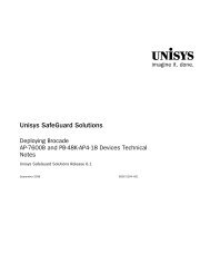
1–2. I/O Module for the <strong>Dorado</strong> <strong>800</strong> (Front View) ............................................................ 1–4<br />
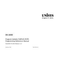
1–3. I/O Module for the <strong>Dorado</strong> <strong>800</strong> (Rear View) ............................................................. 1–5<br />
1–4. <strong>Dorado</strong> <strong>400</strong> Series Cabinet Layout .............................................................................. 1–7<br />
1–5. <strong>Dorado</strong> <strong>400</strong>0 Series Cabinet Layout with One to Two I/O Expansion<br />
Modules ......................................................................................................................... 1–8<br />
1–6. <strong>Dorado</strong> 4050 <strong>Server</strong> Cabinet Layout ........................................................................... 1–9<br />
1–7. <strong>Dorado</strong> <strong>4100</strong> Series Cabinet Layout with One to Two I/O Expansion<br />
Modules ....................................................................................................................... 1–10<br />
1–8. <strong>Dorado</strong> 4150 <strong>Server</strong> Cabinet Layout .......................................................................... 1–11<br />
1–9. I/O manager for the <strong>Dorado</strong> <strong>4200</strong> Series ................................................................. 1–12<br />
1–11. Primary and Secondary PCI Bus Location ................................................................ 1–16<br />
1–12. IOP Card ............................................................................................................................ 1–17<br />
1–13. Top View of the I/O Module ........................................................................................ 1–20<br />
1–14. I/O Module Connection to Expansion Racks .......................................................... 1–21<br />
1–15. Internal I/O Module Layout for the <strong>Dorado</strong> <strong>700</strong> ..................................................... 1–21<br />
1–16. Remote (External) I/O Module Layout for the <strong>Dorado</strong> <strong>700</strong> ................................. 1–22<br />
1–17. IOPs in an I/O Module ................................................................................................... 1–22<br />
1–18. Minimum Connection Configuration for <strong>Dorado</strong> <strong>400</strong>0 I/O .................................. 1–26<br />
1–19. Maximum Configuration for <strong>Dorado</strong> <strong>400</strong>0 I/O ........................................................ 1–26<br />
1–20. Minimum Connection Configuration for <strong>Dorado</strong> <strong>4100</strong> I/O ................................... 1–27<br />
1–21. Maximum Configuration for <strong>Dorado</strong> <strong>4100</strong> I/O ........................................................ 1–27<br />
1–22. PCI Host Bridge Card Handle and Connector ......................................................... 1–28<br />
1–23. PCI Expansion Rack Layout ......................................................................................... 1–30<br />
1–24. <strong>Dorado</strong> <strong>300</strong> Cabinet with IP Cells and I/O Cells ..................................................... 1–33<br />
1–25. OS 2200 I/O Addressing ............................................................................................... 1–35<br />
1–26. Fibre Card Handle With Dual Ports ............................................................................ 1–38<br />
1–27. SCSI Channel Card Handle ........................................................................................... 1–41<br />
1–28. SCSI LVD – HVD Converter .......................................................................................... 1–42<br />
1–29. SBCON Channel Card Handle ...................................................................................... 1–43<br />
1–30. Bus-Tech FICON HBA .................................................................................................... 1–45<br />
1–31. Single-Port Fiber Ethernet Handle and Connector ................................................. 1–49<br />
1–32. Single-Port Copper Ethernet Handle and Connector ............................................ 1–50<br />
1–33. Dual-Port Fiber NIC ........................................................................................................ 1–52<br />
1–34. Dual-Port Copper NIC .................................................................................................... 1–53<br />
1–35. IDE Cable Connection on DVD Interface Card ........................................................ 1–55<br />
1–36. Myrinet Card 2G and Connector ................................................................................. 1–56<br />
1–37. Myrinet Card 10G ............................................................................................................ 1–56<br />
1–38. Clock Synchronization Board ....................................................................................... 1–58<br />
1–39. CSB Handle and BNC Connector ................................................................................ 1–58<br />
2–1. Example JBOD Configuration (First 4 of 18 Disks) ................................................. 2–4<br />
2–2. Arbitrated Loop ................................................................................................................. 2–7<br />
3839 6586–010 xi
Figures<br />
2–3. OS 2200 View of Arbitrated Loop Example ..............................................................2–8<br />
2–4. Switched Fabric Example ............................................................................................... 2–9<br />
2–5. OS 2200 View of Switched Fabric Example ............................................................ 2–10<br />
2–6. Direct-Attach CLARiiON System ................................................................................ 2–12<br />
2–7. OS 2200 View of Channel for Nonredundant Disks .............................................. 2–13<br />
2–8. Unit-Duplexed Configuration ....................................................................................... 2–14<br />
2–9. Multihost Configuration ................................................................................................ 2–18<br />
2–10. OS 2200 View of Tape Drives ..................................................................................... 2–18<br />
2–11. Load-Balanced SAN ...................................................................................................... 2–20<br />
2–12. Daisy Chaining with Eight Control Units ................................................................... 2–21<br />
2–13. Redundant SAN ............................................................................................................. 2–23<br />
2–14. Redundant Daisy Chaining .......................................................................................... 2–24<br />
2–15. Redundant SAN with Remote Tapes ........................................................................2–27<br />
2–16. FC / SCSI Converter ...................................................................................................... 2–28<br />
2–17. Single-Port Configuration ............................................................................................ 2–30<br />
2–18. JBOD Disk Configuration............................................................................................. 2–32<br />
2–19. SCSI Disk Configuration Example (Only 16 of the 80 Disks Shown) ................ 2–34<br />
2–20. Tapes Using SBCON Directors .................................................................................. 2–37<br />
2–21. Configuring Two Hosts Through One Director ..................................................... 2–39<br />
2–22. Configuring Two Hosts Through Two Directors ................................................... 2–40<br />
2–23. Chained SBCON Directors .......................................................................................... 2–42<br />
3–1. OS 2200 Architecture Subsystem .............................................................................. 3–3<br />
3–2. Daisy-Chained JBOD Disks ........................................................................................... 3–4<br />
3–3. I/O Request Servicing Without IOCQ .........................................................................3–5<br />
3–4. The Effect of IOCQ.......................................................................................................... 3–6<br />
3–5. Time for One I/O .............................................................................................................. 3–8<br />
3–6. Time for Multiple I/Os .................................................................................................... 3–9<br />
3–7. Single-Channel Control Units (CU).............................................................................. 3–10<br />
3–8. Multiple Channel Control Units ................................................................................... 3–11<br />
3–9. EMC Symmetrix Data Flow.......................................................................................... 3–14<br />
3–10. Disk Device Terminology ............................................................................................. 3–16<br />
3–11. I/O Request Time Breakdown .................................................................................... 3–17<br />
3–12. Disk Queue Impact ....................................................................................................... 3–20<br />
3–13. Transfer Time ................................................................................................................. 3–23<br />
3–14. Hardware Service Time Affected by Cache-Hit Rate .......................................... 3–24<br />
3–15. Requests Join a Queue ............................................................................................... 3–25<br />
3–16. Response Time .............................................................................................................. 3–26<br />
3–17. Queue Sizes .................................................................................................................... 3–27<br />
3–18. SRDF Modes ................................................................................................................... 3–30<br />
3–19. Synchronous Mode ........................................................................................................ 3–31<br />
4–1. 36-Track Tape .................................................................................................................... 4–1<br />
4–2. Helical Scan ....................................................................................................................... 4–7<br />
4–3. 288-Track Tape ................................................................................................................ 4–7<br />
4–4. File on a Labeled Tape .................................................................................................. 4–11<br />
4–5. T9840A/B Write Performance ................................................................................... 4–14<br />
5–1. <strong>Dorado</strong> <strong>300</strong> and <strong>Dorado</strong> <strong>400</strong> PCI Bus Structure ......................................................5–3<br />
5–2. <strong>Dorado</strong> <strong>700</strong>, <strong>Dorado</strong> <strong>400</strong>0, and <strong>Dorado</strong> <strong>4100</strong> PCI Bus Structure ........................ 5–4<br />
5–3. <strong>Dorado</strong> <strong>800</strong> and <strong>Dorado</strong> <strong>4200</strong> PCI Bus Structure ....................................................5–5<br />
5–4. SIOP: <strong>Dorado</strong> <strong>300</strong> I/Os per Second ........................................................................... 5–13<br />
xii 3839 6586–010
Figures<br />
5–5. SIOP: <strong>Dorado</strong> <strong>700</strong> I/Os per Second ........................................................................... 5–13<br />
5–6. SIOP: <strong>Dorado</strong> <strong>800</strong> I/Os per Second ........................................................................... 5–14<br />
5–7. SIOP: <strong>Dorado</strong> <strong>4200</strong> I/Os per Second ......................................................................... 5–14<br />
5–8. SIOP: <strong>Dorado</strong> <strong>300</strong> MB per Second ............................................................................ 5–15<br />
5–9. SIOP: <strong>Dorado</strong> <strong>700</strong> MB per Second ............................................................................ 5–15<br />
5–10. SIOP: <strong>Dorado</strong> <strong>800</strong> MB per Second ............................................................................ 5–15<br />
5–11. SIOP: <strong>Dorado</strong> <strong>4200</strong> MB per Second .......................................................................... 5–16<br />
5–12. <strong>Dorado</strong> <strong>800</strong> I/O Manager Throughput Ratios ......................................................... 5–16<br />
5–13. <strong>Dorado</strong> <strong>4200</strong> I/O Manager Throughput Ratios ....................................................... 5–17<br />
5–14. SIOP Fibre HBA: I/Os per Second .............................................................................. 5–18<br />
5–15. <strong>Dorado</strong> <strong>800</strong> Single Port Fibre HBA: I/Os per Second............................................ 5–18<br />
5–16. <strong>Dorado</strong> <strong>4200</strong> Single Port Fibre HBA: I/Os per Second ......................................... 5–19<br />
5–17. SIOP Fibre HBA: MB per Second ............................................................................... 5–19<br />
5–18. <strong>Dorado</strong> <strong>800</strong> Single Port Fibre HBA: MB per Second ............................................ 5–20<br />
5–19. <strong>Dorado</strong> <strong>4200</strong> Single Port Fibre HBA: MB per Second ......................................... 5–20<br />
5–20. <strong>Dorado</strong> <strong>800</strong> Single Port Fibre HBA Throughput Ratio .......................................... 5–21<br />
5–21. <strong>Dorado</strong> <strong>4200</strong> Single Port Fibre HBA Throughput Ratio ........................................ 5–21<br />
5–22. SIOP Fibre Disk: Sequential I/O .................................................................................. 5–22<br />
5–23. SIOP Fibre Tape: Sequential I/O................................................................................. 5–22<br />
5–24. SIOP SCSI Compared to CSIOP SCSI ........................................................................ 5–23<br />
5–25. SIOP SBCON Tape Performance ............................................................................... 5–24<br />
5–26. SIOP/CSIOP Performance Ratio (SBCON Tape) .................................................... 5–24<br />
5–27. Multiple Drive SIOP FICON Performance ................................................................ 5–25<br />
5–28. Single Drive/Device SIOP FICON Performance Ratio Relative to<br />
SBCON Baseline ....................................................................................................... 5–25<br />
6–1. Arbitrated Loop ................................................................................................................. 6–2<br />
6–2. Switched Fabric Topology............................................................................................. 6–5<br />
6–3. Switched Fabric ............................................................................................................... 6–6<br />
6–4. FC / SCSI Converter ........................................................................................................ 6–9<br />
6–5. Brocade Switch ............................................................................................................... 6–16<br />
6–6. Zoning ................................................................................................................................ 6–18<br />
6–7. Zoning with Multiple Switches ................................................................................... 6–19<br />
6–8. Multihost Zoning ............................................................................................................ 6–20<br />
6–9. Remote Backup .............................................................................................................. 6–21<br />
7–1. Unit Duplexing and RAID 1 .......................................................................................... 7–33<br />
7–2. CLARiiON Disk System ................................................................................................ 7–34<br />
7–3. CLARiiON System with Unit Duplexing ................................................................... 7–34<br />
8–1. SBCON Channel to Peripheral Distances .................................................................. 8–3<br />
8–2. SBCON Cable Connections ........................................................................................... 8–4<br />
8–3. SBCON Cable or Connector Types ............................................................................. 8–5<br />
8–4. Trunk Cables ..................................................................................................................... 8–6<br />
8–5. Usage of Trunk and Jumper Cables ............................................................................8–7<br />
3839 6586–010 xiii
Figures<br />
xiv 3839 6586–010
Tables<br />
1–1. <strong>Dorado</strong> <strong>800</strong> I/O Styles ..................................................................................................... 1–5<br />
1–2. <strong>Dorado</strong> <strong>300</strong> and <strong>400</strong> IOP Card Styles ....................................................................... 1–17<br />
1–3. <strong>Dorado</strong> <strong>700</strong>, <strong>800</strong>, <strong>400</strong>0, <strong>4100</strong>, and <strong>4200</strong> IOP Styles .............................................. 1–18<br />
1–4. PCI Host Bridge Card Style .......................................................................................... 1–28<br />
1–5. Expansion Rack ............................................................................................................... 1–29<br />
1–6. <strong>Dorado</strong> <strong>4200</strong> Series PCI Card Placement ...................................................................... 1–32<br />
DORADO <strong>4200</strong> SERIES Slot ........................................................................................................ 1–32<br />
1–7. Fibre Channel Style ........................................................................................................ 1–39<br />
1–8. SCSI HBA Style ............................................................................................................... 1–41<br />
1–9. SCSI Converter Styles ................................................................................................... 1–43<br />
1–10. SBCON HBA Style ......................................................................................................... 1–44<br />
1–11. PCIOP-E PDID assignments for Bus-Tech FICON HBA ........................................ 1–45<br />
1–12. Ethernet Styles................................................................................................................1–48<br />
1–13. Myrinet Card Style ......................................................................................................... 1–57<br />
1–14. Partition Time Values Compared to Source Time Values .................................... 1–59<br />
1–15. Myrinet Card Style ......................................................................................................... 1–60<br />
1–16. Cipher Appliance Style .................................................................................................. 1–61<br />
2–1. ANSI and ISO Standards for SCSI Fibre Channel ...................................................... 2–1<br />
2–2. SCMS II View of JBOD Configuration ........................................................................ 2–4<br />
2–3. SCMS II View of Arbitrated Loop Example................................................................2–8<br />
2–4. SCMS II View of Switched Fabric ............................................................................... 2–10<br />
2–5. SCMS II View of Channel for Nonredundant Disks ............................................... 2–13<br />
2–6. SCMS II View of Unit-Duplexed Example ................................................................ 2–15<br />
2–7. T9x40 Family of Tape Drive Styles ............................................................................ 2–16<br />
2–8. SCMS II View of Switched Fabric ............................................................................... 2–19<br />
2–9. SCMS II Values in Daisy-Chain of Eight Control Units ...........................................2–22<br />
2–10. SCMS II View of Redundant Daisy Chains .............................................................. 2–25<br />
2–11. JBOD Disk Subsystems and Target Addresses..................................................... 2–31<br />
2–12. Control-Unit-Based Disk Channels and Addresses .............................................. 2–34<br />
2–13. SCMS II Configuration for SBCON ............................................................................ 2–37<br />
2–14. FICON 32-bit Target Address Fields ......................................................................... 2–45<br />
2–15. FICON target address for direct-connected real tapes – point to<br />
point. ............................................................................................................................ 2–45<br />
2–16. FICON target address for direct-connected virtual tapes – point to<br />
point. ............................................................................................................................ 2–46<br />
2–17. FICON target address for switch-connected real tapes – switched<br />
point to point or Cascade FICON switches. ...................................................... 2–46<br />
2–18. FICON target address for switch-connected virtual tapes – switched<br />
point to point or Cascade FICON switches. ...................................................... 2–46<br />
3–1. Word-to-Kilobyte Translation ..................................................................................... 3–24<br />
3839 6586–010 xv
Tables<br />
4–1. 36-Track Model Performance Metrics ...................................................................... 4–2<br />
4–2. Performance Values for the T9840 Family of Tapes ............................................. 4–3<br />
4–3. Transfer Rates for Labeled Tapes ............................................................................. 4–12<br />
4–4. Translation of Tracks to Words ................................................................................. 4–14<br />
4–5. Transfer Rate Based on File Size ............................................................................... 4–16<br />
4–6. Block Size Options for COPY,G ................................................................................. 4–25<br />
5–1. Busy Percentage per Path ............................................................................................ 5–9<br />
5–2. Translation of Tracks to Words and Bytes .............................................................. 5–12<br />
5–3. Tape Drives Guidelines ................................................................................................ 5–26<br />
6–1. Arbitrated Loop Addressing ......................................................................................... 6–3<br />
6–2. Arbitrated Loop With Eight JBOD Disks ................................................................... 6–4<br />
6–3. 24-Bit Port Address Fields ........................................................................................... 6–10<br />
6–4. 12-bit SAN Addressing Example ................................................................................. 6–14<br />
6–5. 24-bit SAN Addressing Example ................................................................................ 6–16<br />
7–1. Supported Features for the T10000A and T9840D Tape Devices ......................7–8<br />
7–2. SCSI and SBCON Compatibility Matrix ..................................................................... 7–14<br />
7–3. Capabilities Supported by the Exec ......................................................................... 7–20<br />
7–4. DMX Series Characteristics .........................................................................................7–27<br />
7–5. Symmetrix <strong>800</strong>0 Series ................................................................................................7–27<br />
7–6. EMC Symmetrix 5.5 ...................................................................................................... 7–28<br />
7–7. EMC Symmetrix 5.0 ...................................................................................................... 7–28<br />
7–8. EMC Symmetrix 4.8 ICDA ........................................................................................... 7–28<br />
7–9. EMC Symmetrix 4.0 ...................................................................................................... 7–29<br />
7–10. Unit-Duplexed Pairs ...................................................................................................... 7–35<br />
8–1. LVD-HVD Converter Styles ............................................................................................ 8–1<br />
8–2. Supported Expansion Rack CIOP NICs ...................................................................... 8–9<br />
8–3. Supported XIOP and XPC-L NIC .................................................................................. 8–10<br />
9–1. CEC Equipment That Can Be Migrated ....................................................................... 9–1<br />
9–2. Supported Tape Devices ............................................................................................... 9–4<br />
9–3. Supported Cartridge Library Units .............................................................................. 9–6<br />
9–4. End-of-Life Tapes ............................................................................................................ 9–6<br />
9–5. End-of-Life (EOL) Table Libraries .................................................................................. 9–7<br />
9–6. Supported Disk Devices ................................................................................................ 9–8<br />
9–7. Supported SAIL Disks ................................................................................................... 9–10<br />
9–8. Supported DVDs ............................................................................................................. 9–11<br />
9–9. Supported Non-RoHS Host Bus Adapters (HBAs) ................................................ 9–12<br />
9–10. Supported RoHS Host Bus Adapters (HBAs) ......................................................... 9–12<br />
9–11. SIOP Device Mnemonics (By Mnemonic) ................................................................ 9–14<br />
9–12. SIOP Device Mnemonic (By Device) ......................................................................... 9–16<br />
9–13. Ethernet NICs .................................................................................................................. 9–19<br />
9–14. Ethernet NICs ................................................................................................................. 9–20<br />
9–15. Ethernet NICs ................................................................................................................. 9–20<br />
9–16. Ethernet NICs ................................................................................................................. 9–20<br />
A–1. Allowed Positions on an Arbitrated Loop ................................................................. A–1<br />
xvi 3839 6586–010
Tables<br />
B–1. Brocade Switch Addresses .......................................................................................... B–2<br />
B–2. Older Model McData Switch Addresses .................................................................. B–9<br />
B–3. Newer Model McData Switch Addresses (ED10000, 4<strong>400</strong>, 4<strong>700</strong>) .................. B–16<br />
C–1. Key Hardware Attributes by Release ......................................................................... C–1<br />
3839 6586–010 xvii
Tables<br />
xviii 3839 6586–010
Section 1<br />
PCI-Based I/O Hardware<br />
This section covers the configuration of the Peripheral Component Interconnect<br />
(PCI)-based hardware, I/O processors, host bus adapters (HBAs), and network<br />
interface cards (NICs). It is intended to help the service representative set up and<br />
maintain the I/O hardware complex.<br />
Note: The <strong>Dorado</strong> <strong>400</strong>, <strong>400</strong>0, <strong>4100</strong> and <strong>4200</strong> Series only support the SIOP PCI-based<br />
I/O hardware.<br />
Documentation Updates<br />
This document contains all the information that was available at the time of<br />
publication. Changes identified after release of this document are included in problem<br />
list entry (PLE) 18899124. To obtain a copy of the PLE, contact your Unisys<br />
representative or access the current PLE from the Unisys Product Support Web site:<br />
http://www.support.unisys.com/all/ple/18899124<br />
Note: If you are not logged into the Product Support site, you will be asked to do<br />
so.<br />
1.1. Architecture Overview<br />
With the introduction of the <strong>Dorado</strong> <strong>300</strong> Series, the architecture of the <strong>Dorado</strong><br />
systems was revolutionized. The <strong>Dorado</strong> <strong>400</strong>, <strong>400</strong>0, <strong>4100</strong>, and <strong>4200</strong> Series systems<br />
move that revolution forward.<br />
1.1.1. <strong>Dorado</strong> <strong>300</strong> Series<br />
The <strong>Dorado</strong> <strong>300</strong> Series systems contain cell pairs. One cell contains the instruction<br />
processors (IPs) and is attached to another cell for input/output (I/O).<br />
The minimum configuration contains the following:<br />
• One IP cell with 4 OS 2200 IPs and 4 GB of memory<br />
• One I/O cell<br />
For systems with more than one IP cell, the cells are arranged so that the IP cells are<br />
adjacent. For example, IP cell 0 is adjacent to IP cell 1. I/O cell 0 is below the two IP<br />
cells and I/O cell 1 is above the two IP cells.<br />
3839 6586–010 1–1
PCI-Based I/O Hardware<br />
The following illustration shows the layout of a <strong>Dorado</strong> <strong>300</strong> cabinet. The minimum<br />
configuration is shown with solid lines and white background, and dashed lines with<br />
gray background are used for customer-optional equipment.<br />
1.1.2. <strong>Dorado</strong> <strong>700</strong> Series<br />
Figure 1–1. <strong>Dorado</strong> <strong>300</strong> Series Cabinet Layout<br />
The <strong>Dorado</strong> <strong>700</strong> is similar to the <strong>Dorado</strong> <strong>300</strong> in the cabinets. The differences are<br />
<strong>Dorado</strong> 740 and <strong>Dorado</strong> 750<br />
• IP cell with four OS 2200 IPs and 4 GB of memory<br />
• PCI-X based PCIOP-E I/O processor and Channel cards<br />
• Support for Internal I/O only with a maximum of four IOPs (SIOP, CIOP, and XIOP)<br />
• No support for connection to XPC-L<br />
1–2 3839 6586–010
<strong>Dorado</strong> 780 and <strong>Dorado</strong> 790<br />
PCI-Based I/O Hardware<br />
• Faster 2200 processor (about 15 percent faster than <strong>Dorado</strong> 740 and <strong>Dorado</strong> 750)<br />
• PCI-X based PCIOP-E I/O processor and Channel cards<br />
• Support for External I/O with a maximum of six IOPs in a Remote I/O Module<br />
(SIOP, CIOP, and XIOP)<br />
• Support for XPC-L connectivity through the PCIOP-E version of the XIOP<br />
<strong>Dorado</strong> <strong>700</strong> series I/O Configuration<br />
The I/O for the <strong>Dorado</strong> <strong>700</strong> Series can either be Internal with a maximum of four IOP<br />
cards for each cell (740 and 750) or External with a maximum of six IOP cards for each<br />
Remote I/O Module (780 and 790).<br />
The Internal I/O contains one to four I/O Processor units (PCIOP-E) with each PCIOP-E<br />
connecting to a PCI Expansion Rack. The PCI Expansion Rack can contain either<br />
standard channel cards or NIC cards. Each PCIOP-E requires a separate expansion rack<br />
and can have only NIC cards or storage HBA cards, but cannot have both in the same<br />
rack.<br />
The External I/O is located in the Remote I/O Module. The Remote I/O Module<br />
contains one to six I/O Processor units (PCIOP-E). The same PCI Expansion Racks<br />
connect to the external I/O processors.<br />
The Internal I/O or the Remote I/O Module does not contain PCI Channel cards. They<br />
are located in the PCI Expansion Racks.<br />
Notes:<br />
• Internal I/O DVD – The PCIOP-E card used for connection to the DVD drive can<br />
only be inserted in IOPx1 slot when viewed from the rear of the IP Cell, due to<br />
cable routing within the cell. The DVD appears as PDID=61392 (xEFD0 or<br />
167720), CU address=0, Device address =0.<br />
• External I/O DVD – The PCIOP-E card used for connection to the DVD drive can<br />
only be inserted in IOPx5 slot when viewed from the rear of the Remote I/O<br />
Module, due to cable routing within the cell. The DVD appears as PDID=61392<br />
(xEFD0 or 167720), CU address=0, Device address =0.<br />
Each PCIOP-E (SIOP, CIOP, and XIOP) requires two cables, a communications cable,<br />
and an I/O cable. The Remote I/O Module contains the platform logic for primary PCI<br />
buses. These PCI buses are where the PCIOP-E boards are attached.<br />
The PCIOP-E contains the I/O processor (IOP) and the 36-bit data formatter needed to<br />
perform the I/O operations. The primary PCI bus is connected to the memory side of<br />
the formatter and IOP bridges. A secondary PCI bus is attached to the channel side of<br />
the bridges. PCI cards that support the IDE DVD drive and the three inbuilt SAS drives<br />
must be installed in one of the available PCI slots to drive these interfaces.<br />
The PCIOP-E and PCI cards can be hot replaced, but only if their status is DOWN.<br />
3839 6586–010 1–3
PCI-Based I/O Hardware<br />
The PCI cards can consume a maximum of 25 watts each, drawing power from either<br />
the 3.3 volt or the 5 volt rails, or both, as long as the sum of both does not exceed<br />
25 watts for each card.<br />
1.1.3. <strong>Dorado</strong> <strong>800</strong> Series<br />
The <strong>Dorado</strong> <strong>800</strong> series has the following configuration:<br />
• Cells ranging from a single cell with 4 IPs to 8 cells with 32 IPs<br />
• Maximum memory of 256 GB<br />
• Support for internal I/O and external I/O using PCIOP-M cards (SIOP, CIOP, XIOP)<br />
<strong>Dorado</strong> <strong>800</strong> Series I/O Configuration<br />
<strong>Dorado</strong> <strong>800</strong> utilizes the I/O Manager Module PCIOP-Ms for the storage (SIOP-M) and<br />
communication IOPs (CIOP-M), and the PCIOP-E for the initial delivery of the XIIP (also<br />
called XIOP). The PCIOP-E cannot be used for storage or communication IOPs.<br />
The I/O Manager is a 4U module that consists of two PCIOP-Ms. Each of the PCIOP-<br />
Ms can be a storage IOP (SIOP-M) or communications IOP (CIOP-M) or future XIOP-M.<br />
The PCIOP-M consists of the I/O processing engine and slots for up to six PCIe add-in<br />
cards (NICs or HBAs). The PCIOP-M connects to the rest of the <strong>Dorado</strong> <strong>800</strong> system<br />
through the Host Card installed in the Internal or Remote I/O Module. The Host Bridge<br />
card is simply a PCI-X to PCIe bridge, with no processing logic.<br />
Figure 1–2. I/O Module for the <strong>Dorado</strong> <strong>800</strong> (Front View)<br />
1–4 3839 6586–010
PCI-Based I/O Hardware<br />
Figure 1–3. I/O Module for the <strong>Dorado</strong> <strong>800</strong> (Rear View)<br />
The following are the styles for the <strong>Dorado</strong> <strong>800</strong> I/O.<br />
Table 1–1. <strong>Dorado</strong> <strong>800</strong> I/O Styles<br />
Style Description<br />
DOR204-IOM I/O Manager Rack with two PCIOP-Ms<br />
DOR1-HST <strong>Dorado</strong> I/O Manager PCI-X to PCIe card and 5m<br />
cable (2 required per DOR204-IOM)<br />
DOR<strong>800</strong>-CIO I/O: <strong>Dorado</strong> <strong>800</strong> Series - Communications IOP<br />
DOR<strong>800</strong>-SIO I/O: <strong>Dorado</strong> <strong>800</strong> Series - Storage IOP<br />
ETH10201-PCE PCIe 2 Port 1 Gb Ethernet (Fiber)<br />
ETH20201-PCE PCIe 2 Port 1 Gb Ethernet (Copper)<br />
ETH10210-PCE PCIe 2 Port 10 Gb Ethernet (Fiber)<br />
FCH9430232-PCE Fibre Channel 4Gb – 2 port<br />
FCH9540231-PCE Fibre Channel 8Gb – 2 port<br />
FIC1001-PCE FICON Channel 4Gb – 1 port<br />
CIP2001-PCE Nitrox Cypher<br />
CSB1-PCE Time card<br />
Configuration rules are required for the location of the Host Channel Cards for the<br />
PCIOP-Ms in the Internal and Remote I/O Modules and the connection of the IOPs<br />
(PCIOP-Ms) in the I/O Manager module to these cards.<br />
With the PCIOP-E, the PCIOP-E is installed in the Internal or Remote I/O Module and<br />
connects to the Expansion rack, which contains the XIIP interface card.<br />
3839 6586–010 1–5
PCI-Based I/O Hardware<br />
All of the I/O slots in the Internal I/O Module in the <strong>Dorado</strong> <strong>800</strong> are PCI-X 133MHz. In<br />
the Remote I/O Module, only three of the I/O slots are PCI-X 133MHz, the remaining<br />
three slots are PCI-X 100MHz. The SIOP-M requires the highest bandwidth. The<br />
configuration rules for the <strong>Dorado</strong> <strong>800</strong> must assign the SIOP-M first to the 133MHz<br />
PCI-X buses and then use the 100MHz PCI-X buses.<br />
For more information on the PCI-card slot assignments, see Section 1.3.3 I/O<br />
Expansion Module (Internal or External) for the <strong>Dorado</strong> <strong>800</strong>.<br />
The IOP logical number to PCI-card slot assignments are the same in the Internal I/O<br />
Module and the Remote I/O Module due to the software configuration based on the<br />
PCI assignments. To keep the configurations the same for Internal I/O Modules or<br />
Remote I/O Modules, the same rules are utilized for the Host card assignments.<br />
1.1.4. <strong>Dorado</strong> <strong>400</strong> <strong>Server</strong><br />
For the <strong>Dorado</strong> <strong>400</strong> <strong>Server</strong> systems, the configuration contains the following:<br />
• One internal I/O cell containing<br />
− High-level high-speed Xeon® Processor MP processors<br />
− 16 GB memory<br />
− Dual-port network interface<br />
− Read-only DVD for SAIL only<br />
• One Procnode cell without processors or memory<br />
• One remote I/O cell<br />
− Read/Write DVD for OS 2200<br />
− Up to 3 other SIOPs<br />
• One Managed LAN Switch<br />
• One Operations <strong>Server</strong><br />
The following illustration shows the layout of the <strong>Dorado</strong> <strong>400</strong>, <strong>400</strong>0, and <strong>4100</strong> cabinet.<br />
The minimum configuration is shown with solid lines and white background, and<br />
dashed lines with gray background are used for customer-optional equipment.<br />
1–6 3839 6586–010
1.1.5. <strong>Dorado</strong> <strong>400</strong>0 <strong>Server</strong><br />
Figure 1–4. <strong>Dorado</strong> <strong>400</strong> Series Cabinet Layout<br />
PCI-Based I/O Hardware<br />
The <strong>Dorado</strong> <strong>400</strong>0 <strong>Server</strong> contains the following changes from the <strong>Dorado</strong> <strong>400</strong> Series:<br />
• Utilizes the <strong>ClearPath</strong> <strong>400</strong>0 cell for processing.<br />
• Utilizes the PCIOP-E in the I/O Expansion Module for SIOP.<br />
• The <strong>ClearPath</strong> <strong>400</strong>0 cell connects to the I/O Expansion Module.<br />
• The I/O Expansion Module connects to the PCI Channel Module.<br />
3839 6586–010 1–7
PCI-Based I/O Hardware<br />
The following <strong>Dorado</strong> <strong>400</strong>0 cabinet layout is with one or two I/O Expansion Modules.<br />
The minimum configuration is shown with a white background and a gray background<br />
is used for customer-optional equipment.<br />
Figure 1–5. <strong>Dorado</strong> <strong>400</strong>0 Series Cabinet Layout with One to Two I/O Expansion<br />
Modules<br />
<strong>Dorado</strong> 4050 <strong>Server</strong><br />
The <strong>Dorado</strong> 4050 <strong>Server</strong> is an entry level model with a fixed configuration. The <strong>Dorado</strong><br />
4050 is similar to the <strong>Dorado</strong> <strong>400</strong>0 in the cabinets, but the following options are not<br />
available<br />
• Flexibililty of configuring IOPs and HBAs<br />
• A redundant switch<br />
• External SAIL disk<br />
• SBCON/ESCON HBA<br />
• Cavium Nitrox (Encryption) card<br />
• High Availability<br />
1–8 3839 6586–010
The following illustration shows the layout of the <strong>Dorado</strong> 4050 cabinet.<br />
1.1.6. <strong>Dorado</strong> <strong>4100</strong> <strong>Server</strong><br />
Figure 1–6. <strong>Dorado</strong> 4050 <strong>Server</strong> Cabinet Layout<br />
PCI-Based I/O Hardware<br />
The only difference for the <strong>Dorado</strong> <strong>4100</strong> <strong>Server</strong> from the <strong>Dorado</strong> <strong>400</strong>0 Series is that it<br />
uses the <strong>ClearPath</strong> <strong>4100</strong> cell for processing.<br />
The following <strong>Dorado</strong> <strong>4100</strong> cabinet layout is with one or two I/O Expansion Modules.<br />
The minimum configuration is shown with a white background and a gray background<br />
is used for customer-optional equipment.<br />
3839 6586–010 1–9
PCI-Based I/O Hardware<br />
Figure 1–7. <strong>Dorado</strong> <strong>4100</strong> Series Cabinet Layout with One to Two I/O Expansion<br />
Modules<br />
<strong>Dorado</strong> 4150 <strong>Server</strong><br />
The <strong>Dorado</strong> 4150 <strong>Server</strong> is an entry level model with a fixed configuration. The <strong>Dorado</strong><br />
4150 is similar to the <strong>Dorado</strong> <strong>4100</strong> in the cabinets, but the following options are not<br />
available<br />
• Flexibililty of configuring IOPs and HBAs<br />
• A redundant switch<br />
• SBCON/ESCON HBA<br />
1–10 3839 6586–010
• Cavium Nitrox (Encryption) card<br />
• High Availability<br />
The following illustration shows the layout of the <strong>Dorado</strong> 4150 cabinet.<br />
1.1.7. <strong>Dorado</strong> <strong>4200</strong> Series<br />
Figure 1–8. <strong>Dorado</strong> 4150 <strong>Server</strong> Cabinet Layout<br />
PCI-Based I/O Hardware<br />
<strong>Dorado</strong> <strong>4200</strong> Series utilizes the I/O Manager that was introduced with the <strong>Dorado</strong> <strong>800</strong><br />
Series. The I/O Manager is a Unisys designed, custom built, 4U module that contains 2<br />
IOPs, with up to 6 PCIe cards per IOP. Connection to the <strong>Dorado</strong> <strong>4200</strong> Series host is<br />
via an industry standard PCIe External Cabling Interconnect. The I/O Manager has a<br />
number of significant advantages over the prior <strong>Dorado</strong> <strong>4100</strong> Series PCIOP-E based<br />
I/O. Among them are:<br />
• Modern and higher bandwidth connection to the host (Gen 2 PCIe)<br />
• Compact packaging (2 IOPs and up to 12 HBAs in 4U rack space)<br />
• Usage of the latest generation HBAs<br />
• Faster processors with lower latency memory accesses<br />
• Mechanical and electrical design that allows for easy replacement of one of the<br />
IOPs within an I/O Manager while the other continues to operate unaffected.<br />
3839 6586–010 1–11
PCI-Based I/O Hardware<br />
Figure 1–9. I/O manager for the <strong>Dorado</strong> <strong>4200</strong> Series<br />
I/O Manager PCIe Connector Ports<br />
This section details cabling restrictions both from the host card to the switch card in<br />
an I/O Manager and from the switch card to an IOP in an I/O Manager. The figure<br />
below shows the rear view of an I/O Manager. The switch card is located on the far<br />
left of the figure, but is not directly visible due to enclosed metal sheet. The switch<br />
card contains four Gen 2 PCIe connector ports mounted vertically- that are visible in<br />
the figure. The switch ports are labeled (from bottom to top) UP-0, DWN-0, DWN-1,<br />
and DWN-2. Additionally, each IOP contains a Gen 2 PCIe connector port. This is<br />
located between the Ethernet port and Slot 0 and mounted horizontally.<br />
1–12 3839 6586–010
PCI-Based I/O Hardware<br />
The following figure represents the switch ports and the cabling between ports.<br />
Figure 1–10: Switch Ports and Cabling<br />
Following are the I/O Manager PCIe connector port cabling rules:<br />
• The PCIe cable connected to the host card must always be connected to switch<br />
card port UP-0 of the first I/O Manager for that slot.<br />
• Switch card port DWN-0 must always be connected to the IOP 0 port.<br />
• Switch card port DWN-1 must always be connected to the IOP 1 port.<br />
• If an additional I/O Manager is connected off the same host card, it must be<br />
connected from switch card port DWN-2 on the first I/O Manager for that slot to<br />
switch card port UP-0 on the second I/O Manager for that slot.<br />
• A maximum of two I/O Managers (four IOPs) may be connected to a single host<br />
card.<br />
Usage of multiple I/O Managers per host slot is not allowed until after each host slot<br />
has first been connected to an I/O Manager (that is, the number of I/O Managers<br />
exceeds the number of host cards).<br />
1.2. I/O Module Overview<br />
The following introduces the terminology and the architecture of the <strong>Dorado</strong> <strong>300</strong>, <strong>400</strong>,<br />
<strong>700</strong>, <strong>400</strong>0, <strong>4100</strong>, and <strong>4200</strong> <strong>Server</strong>s.<br />
Note: For this discussion, consider the <strong>Dorado</strong> <strong>300</strong> and <strong>700</strong> Series I/O Module and<br />
the <strong>Dorado</strong> <strong>400</strong>, <strong>400</strong>0, <strong>4100</strong>, and <strong>4200</strong> Series PCI Channel Module as equivalents.<br />
3839 6586–010 1–13
PCI-Based I/O Hardware<br />
1.2.1. PCI Standard<br />
Caution<br />
The SIOP and earlier SCIOP components are microcoded components. They<br />
are the same devices that may perform roles as an IOP, XIIP, or a PCIOP for<br />
communications. Their base personality is burned into them at the Factory<br />
when they are built. Once a microcode set has been established in them, a<br />
field location attempt to change the set that is installed on the device is not<br />
advised. Doing so makes the device unusable and it will have to be<br />
returned to the factory to be reinitialized. In cases where the hardware is<br />
different, the microcode load attempt will be rejected by the IOP with an<br />
appropriate status code. However, in case of the differences between<br />
<strong>Dorado</strong> <strong>300</strong>, <strong>Dorado</strong> <strong>700</strong> and the <strong>Dorado</strong> <strong>400</strong>, <strong>Dorado</strong> <strong>400</strong>0, <strong>Dorado</strong> <strong>4100</strong> or<br />
<strong>Dorado</strong> <strong>4200</strong> the microcode load attempt will not be rejected. Loading the<br />
<strong>Dorado</strong> <strong>400</strong> or <strong>400</strong>0, <strong>4100</strong> or <strong>4200</strong> version of microcode on an SIOP for a<br />
<strong>Dorado</strong> <strong>300</strong> or <strong>Dorado</strong> <strong>700</strong> will make the device unusable and it will have to<br />
be returned to the factory to be reinitialized. A change will be developed in<br />
IOPUTIL and provided in the near future that will verify that the IOP<br />
Microcode matches the host system that is connected to the SIOP device.<br />
Peripheral Component Interconnect (PCI) provides a processor-independent data path<br />
(a bridge) between the I/O processors and the peripheral controllers (HBAs and NICs).<br />
More than one controller can be attached to the same PCI bus.<br />
PCI is an industry standard, first released by Intel in 1992. The following definitions are<br />
based on the standard:<br />
• Bus Speeds<br />
The original standard, 1.0, supported 33-MHz and 32-bit bus width. Revision 2.1<br />
introduced the possibility of faster cards with a bridge by supporting the following:<br />
− 66-MHz maximum bus speeds<br />
Cards running at 33 MHz are also supported.<br />
− 64-bit bus<br />
64 bits are sent in parallel (at the same time). Potentially, the bus is twice as<br />
fast as a 32-bit bus.<br />
− If any component of a PCI bus runs at 33 MHz, all the components of the bus<br />
run at 33 MHz.<br />
• PCI-PCI Bridges<br />
The original specification allowed four PCI cards, but the number of cards could be<br />
increased by using a PCI bridge. The bridge allows for additional slots, using one<br />
original slot and bridging to another bus that has its own set of slots. PCI-to-PCI<br />
bridges are Application Specific Integrated Circuits (ASICs) that electrically isolate<br />
two PCI buses while enabling bus transfers to be forwarded from one bus to<br />
another. Each bridge device has a primary and a secondary PCI bus. Multiple bridge<br />
devices can be cascaded to create a system with many PCI buses.<br />
1–14 3839 6586–010
PCI-Based I/O Hardware<br />
• ASIC<br />
An ASIC is a custom-designed chip for a specific application. ASICs improve<br />
performance over general-purpose CPUs because ASICs are hardwired to do a<br />
specific job and do not incur the overhead of fetching and interpreting stored<br />
instructions.<br />
• Signaling<br />
The original standard, supported by the technologies of that time, was based on<br />
5.0-volt signaling for the cards and the backplane. As the technology evolved,<br />
3.3-volt signaling became a better choice. However, vendors offered backplanes<br />
that had all the slots supporting either 3.3-volt or 5.0-volt PCI cards. This meant the<br />
PCI cards could not be mixed within the same backplane. Then, PCI add-in card<br />
vendors developed Universal cards that can plug into a 3.3-volt slot or a 5.0-volt<br />
slot.<br />
• PCI Revisions<br />
− Revision 2.1<br />
Supported 3.3-volt cards, 5.0-volt cards, and Universal cards.<br />
− Revision 2.2<br />
Minor changes.<br />
− Revision 2.3<br />
Supported 3.3-volt cards and Universal add-in cards; no support for 5.0-volt<br />
cards.<br />
1.2.2. I/O Bus Layout<br />
The following figure shows the key components of the I/O complex and the primary<br />
and secondary PCI buses that connect them.<br />
The SIOH and P64 are Intel chips used for I/O processing. There is no further<br />
description in this document.<br />
The DVD Interface Card and the PCI Host Bridge Card are specific HBAs. They are<br />
described later in this section.<br />
The expansion rack contains up to seven additional HBAs or NICs. It is described later<br />
in this section.<br />
3839 6586–010 1–15
PCI-Based I/O Hardware<br />
Figure 1–11. Primary and Secondary PCI Bus Location<br />
1.2.3. <strong>Dorado</strong> <strong>300</strong> and <strong>Dorado</strong> <strong>400</strong> IOPs<br />
Each type of IOP has its own microcode. The <strong>Dorado</strong> <strong>300</strong> and <strong>400</strong> <strong>Server</strong>s support the<br />
following type of I/O processor:<br />
• SIOP, Storage IOP<br />
The SIOP supports PCI cards that connect to tapes and disks. The cards are<br />
classified as Host Bus Adapters (HBA). The PCI cards can be Fibre, SCSI, or<br />
SBCON.<br />
The <strong>Dorado</strong> <strong>300</strong> <strong>Server</strong> supports the following types of I/O processors:<br />
• CIOP, Communications IOP<br />
The CIOP supports an Ethernet PCI card. This is also known as a network interface<br />
card (NIC). CIOP is not supported on <strong>Dorado</strong> <strong>400</strong>.<br />
• XIOP, Extended IOP<br />
The XIOP supports one connection to the XPC-L. The Myrinet is the only<br />
supported card. The Myrinet card only goes into slot 0. Slot 1 must remain unused.<br />
XIOP is not supported on <strong>Dorado</strong> <strong>400</strong>.<br />
1–16 3839 6586–010
Styles<br />
The following are the IOP card styles:<br />
Figure 1–12. IOP Card<br />
Table 1–2. <strong>Dorado</strong> <strong>300</strong> and <strong>400</strong> IOP Card Styles<br />
Style Connection<br />
DOR<strong>400</strong>-SIO SIOP for <strong>Dorado</strong> <strong>400</strong> HBAs (PCIOP-D)<br />
DOR380-SIO SIOP for <strong>Dorado</strong> <strong>300</strong> HBAs (PCIOP-D)<br />
DOR380-CIO CIOP for Ethernet NICs for <strong>Dorado</strong><br />
<strong>300</strong><br />
DOR380-XIO XIOP for XPC-L for <strong>Dorado</strong> <strong>300</strong><br />
Dual Paths Needed for Online Loading of SIOP Microcode<br />
PCI-Based I/O Hardware<br />
When online loading microcode into the SIOP, the peripherals (disk or tape) that can be<br />
accessed through that SIOP are not available for normal access by the system. There<br />
must be a redundant SIOP that is UP and can access the same peripherals as the SIOP<br />
being loaded. If this restriction is not met for disks, the online load process could<br />
result in a system stop, system hang, or have unpredictable results.<br />
If you have peripherals that are single path or you are loading several SIOPs, you<br />
should use SUMMIT offline EPTS.<br />
3839 6586–010 1–17
PCI-Based I/O Hardware<br />
1.2.4. <strong>Dorado</strong> <strong>700</strong>, <strong>Dorado</strong> <strong>800</strong>, <strong>Dorado</strong> <strong>400</strong>0, <strong>Dorado</strong> <strong>4100</strong><br />
and <strong>Dorado</strong> <strong>4200</strong> IOPs (PCIOP-M and PCIOP-E)<br />
The PCIOP-M platform is the next generation PCIOP design. The PCIOP-M is attached<br />
to the <strong>Dorado</strong> <strong>800</strong> through a PCI-X to PCI express bridge card.<br />
The PCIOP-M module is a standard rack mount 4U unit. It contains two sub modules,<br />
which to the host are two separate IOPs. Each sub module has 6 on-board PCI express<br />
slots, which support the PCI express standard hot plug controller interface. An<br />
external I/O Expansion rack is not required for the PCIOP-M. Each PCIOP-M has one<br />
DVD, which is only used by the SIOP. The DVD is attached to the sub module on the<br />
left (looking from the rear of the PCIOP-M).<br />
The PCIOP-E is the I/O processor (IOP) to be used on the <strong>Dorado</strong> <strong>700</strong>, <strong>Dorado</strong> <strong>400</strong>0,<br />
and <strong>Dorado</strong> <strong>4100</strong> <strong>Server</strong>s. The IOP fits into a standard full-sized PCI slot. The PCI<br />
channel cards (HBAs) require an external I/O Expansion Module attached to each IOP.<br />
Note: For the <strong>Dorado</strong> <strong>700</strong>, the PCIOP-E card used for connection to the DVD drive<br />
can only be inserted in the left-most slot (internal I/O = PCIBUS_x_3, Remote<br />
I/O=PCIBUS_x_2) due to cable routing within the cell.<br />
Table 1–3. <strong>Dorado</strong> <strong>700</strong>, <strong>800</strong>, <strong>400</strong>0, <strong>4100</strong>, and <strong>4200</strong> IOP<br />
Styles<br />
Style Connection<br />
DOR<strong>700</strong>-SIO SIOP for <strong>Dorado</strong> <strong>700</strong> HBAs (PCIOP-E)<br />
DOR<strong>800</strong>-SIO SIOP-M for <strong>Dorado</strong> <strong>800</strong> HBAs (PCIOP-M)<br />
DOR<strong>400</strong>0-SIO SIOP for <strong>Dorado</strong> <strong>400</strong>0 and <strong>4100</strong> HBAs (PCIOP-E)<br />
DOR<strong>700</strong>-CIO CIOP for Ethernet NICs for <strong>Dorado</strong> <strong>700</strong><br />
DOR<strong>800</strong>-CIO PCIOP-M for Ethernet NICs for <strong>Dorado</strong> <strong>800</strong><br />
DOR<strong>700</strong>-XIO XIOP for XPC-L for <strong>Dorado</strong> <strong>700</strong><br />
DOR<strong>400</strong>0-XIO XIOP for XPC-L for <strong>Dorado</strong> <strong>400</strong>0, <strong>4100</strong> and <strong>4200</strong><br />
1.2.5. Host Bus Adapters<br />
A host bus adapter (HBA) is a printed circuit board that connects one or more<br />
peripheral units to a computer. The HBA manages the transfer of data and information<br />
between the host and the peripheral.<br />
An HBA contains an onboard processor, a protocol controller, and buffer memory. The<br />
HBA receives an I/O request from the operating system and completely handles<br />
activities such as segmentation and reassembly, flow control, error detection and<br />
correction, as well as command processing of the protocol being supported. HBAs<br />
offload the <strong>Dorado</strong> server CPU.<br />
1.2.6. Network Interface Card<br />
1–18 3839 6586–010
PCI-Based I/O Hardware<br />
A network interface card (NIC) connects a computer to a communications network.<br />
For the <strong>Dorado</strong> Series, it is an Ethernet network.<br />
Note: For the <strong>Dorado</strong> <strong>400</strong>, <strong>400</strong>0, <strong>4100</strong>, and <strong>4200</strong> a PCIOP is not required for NICs.<br />
For the <strong>Dorado</strong> <strong>400</strong>, the NICs are installed in the Internal I/O Cell. For the <strong>Dorado</strong><br />
<strong>400</strong>0, <strong>4100</strong>, and <strong>4200</strong> the NICs are installed in the <strong>ClearPath</strong> <strong>400</strong>0, <strong>4100</strong>, and <strong>4200</strong><br />
respectively.<br />
A NIC relies on the server for protocol processing, including such functions as the<br />
following:<br />
• Maintaining packet sequence order<br />
• Segmentation and reassembly<br />
• Error detection and correction<br />
• Flow control<br />
The NIC contains the protocol control firmware and Ethernet Controller needed to<br />
support the Media Access Control (MAC) data link protocol used by Ethernet.<br />
Each network interface card is assigned an Ethernet source address by the<br />
manufacturer of the network interface card. The source address is stored in<br />
programmable read-only memory (PROM) on the network interface card. The<br />
addresses are globally unique.<br />
1.3. I/O Modules and Components<br />
The following describes the I/O modules and components.<br />
1.3.1. I/O Module for the <strong>Dorado</strong> <strong>300</strong> and <strong>400</strong><br />
The I/O Module consists of 12 slots. There is room for 4 IOPs; each IOP can control up<br />
to 2 PCI slots in the I/O Module.<br />
The I/O Module<br />
• Supports PCI revision 2.2<br />
• Supports 3.3-volt or Universal add-in PCI cards<br />
The following figure shows the slots in the I/O Module:<br />
3839 6586–010 1–19
PCI-Based I/O Hardware<br />
Example<br />
Figure 1–13. Top View of the I/O Module<br />
The area in the ellipse shows the locations for IOP1 and the PCI card slots the IOP<br />
controls (more about the types of IOPs and PCI cards later).<br />
The area in the ellipse is set up at the factory with an SIOP in PCI slot 0 and a DVD<br />
Interface Card in PCI slot 1. Due to cable length limitations, this location must be used<br />
for the DVD interface since it is closest to the DVD reader. (For more information on<br />
DVD, see 1.6.2.) The other PCI slot, slot 0, can be used for an SIOP, an HBA, or a PCI<br />
Host Bridge Card to an expansion rack.<br />
The following figure shows IOPs in an I/O Module.<br />
• The CIOP controls two NICs.<br />
• One SIOP has two HBAs.<br />
• One SIOP has an interface to a DVD and a PCI Host Bridge Card to two fibre HBAs<br />
in an expansion rack.<br />
Notes:<br />
• CIOP is not supported on <strong>Dorado</strong> <strong>400</strong>.<br />
• This example does not apply to the <strong>Dorado</strong> <strong>400</strong>0, <strong>4100</strong> or <strong>4200</strong>. See Figures 1–<br />
14, 1–15, 1–16, and 1–17 for the <strong>Dorado</strong> <strong>400</strong>0 and <strong>4100</strong> connections.<br />
1–20 3839 6586–010
Figure 1–14. I/O Module Connection to Expansion Racks<br />
PCI-Based I/O Hardware<br />
1.3.2. I/O Module (Internal or External) for the <strong>Dorado</strong> <strong>700</strong><br />
The Internal I/O Module consists of five slots. There is room for four IOPs; each IOP<br />
can control a maximum of seven PCI slots in the PCI Expansion Rack.<br />
Figure 1–15. Internal I/O Module Layout for the <strong>Dorado</strong> <strong>700</strong><br />
3839 6586–010 1–21
PCI-Based I/O Hardware<br />
Example<br />
The Remote I/O Module (External) consists of 12 slots. There is room for six IOPs;<br />
each IOP can control a maximum of seven PCI slots in the PCI Expansion Rack.<br />
Figure 1–16. Remote (External) I/O Module Layout for the <strong>Dorado</strong> <strong>700</strong><br />
In Figure 1–16, the area in the ellipse shows the locations for IOP0 – IOP5 and possible<br />
locations of the available six IOPs. This is set up at the factory with an SIOP in the IOP5<br />
location which includes the DVD Interface. IOP5 is the default and only location for the<br />
DVD. Only SIOP, CIOP, and XIOP cards can be placed in the Remote I/O Module.<br />
The following figure shows the IOPs in an I/O Module.<br />
Figure 1–17. IOPs in an I/O Module<br />
1–22 3839 6586–010
In this example,<br />
• The CIOP controls seven NICs<br />
• One SIOP has two HBAs<br />
Note: CIOP is not supported on <strong>Dorado</strong> <strong>400</strong>, <strong>400</strong>0, <strong>4100</strong> or <strong>4200</strong>.<br />
PCI-Based I/O Hardware<br />
This example does not apply to the <strong>Dorado</strong> <strong>400</strong>0, <strong>4100</strong> and <strong>4200</strong>. See Figures 1–14, 1–<br />
15, 1-16, and 1–17 for the <strong>Dorado</strong> <strong>400</strong>0 and <strong>4100</strong> connections.<br />
1.3.3. I/O Expansion Module (Internal or External) for the<br />
<strong>Dorado</strong> <strong>800</strong><br />
The <strong>Dorado</strong> <strong>800</strong> utilizes both Internal and Remote I/O Modules.<br />
The Internal I/O Module has five PCI-X card slots, the PCIOP-E or PCIOP-M Host Cards<br />
are installed in these card slots. The location of the card dictates the 2200 logical IOP<br />
number (the cell number is appended to the IOP number to form the complete logical<br />
IOP number). The assignments are as follows.<br />
Internal I/O Module<br />
PCI-X Card Slot<br />
2200 Logical IOP<br />
Number IOP Type Allowed PCI-X Bus Frequency<br />
PCI-X Bus 3/Slot 1 IOP4 Third CIOP-M<br />
SIOP-M if IOP1 and<br />
IOP3 are already<br />
SIOP-Ms<br />
Cannot be XIOP-E<br />
PCI-X Bus 4/Slot 1 IOP1 First SIOP-M<br />
only assign XIOP-E<br />
or CIOP-M if IOP0,<br />
IOP2 and IOP4 are<br />
already used<br />
PCI-X Bus 5/Slot 1 IOP0 First CIOP-M or<br />
XIOP-E<br />
SIOP-M if IOP1 and<br />
IOP3 are already<br />
SIOP-Ms<br />
PCI-X Bus 6/Slot 1 IOP3 Second SIOP-M<br />
only assign XIOP-E<br />
or CIOP-M if IOP0,<br />
IOP2 and IOP4 are<br />
already used<br />
PCI-X Bus 7/Slot 1 IOP2 Second CIOP-M or<br />
XIOP-E<br />
SIOP-M if IOP1 and<br />
IOP3 are already<br />
SIOP-Ms<br />
133MHz<br />
133MHz<br />
133MHz<br />
133MHz<br />
133MHz<br />
3839 6586–010 1–23
PCI-Based I/O Hardware<br />
The Remote I/O Module has eleven PCI-X card slots, but only six of these are used for<br />
the PCIOP-E or PCIOP-M Host Cards. The location of the card dictates the 2200 logical<br />
IOP number (the cell number is appended to the IOP number to form the complete<br />
logical IOP number). The assignments are as follows.<br />
Remote I/O Module<br />
PCI-X Card Slot<br />
2200 Logical IOP<br />
Number IOP Type Allowed PCI-X Bus Frequency<br />
PCI-X Bus 2/Slot 1 IOP5 Third SIOP-M<br />
only assign XIOP-E<br />
or CIOP-M if IOP0,<br />
IOP2, and IOP4 are<br />
already used<br />
PCI-X Bus 3/Slot 1 IOP4 Third CIOP-M<br />
SIOP-M if IOP1,<br />
IOP3 and IOP5 are<br />
already SIOP-Ms<br />
PCI-X Bus 4/Slot 1 IOP1 First SIOP-M<br />
only assign XIOP-E<br />
or CIOP-M if IOP0,<br />
IOP2, and IOP4 are<br />
already used<br />
PCI-X Bus 5/Slot 1== IOP0 First CIOP-M or<br />
XIOP-E<br />
SIOP-M if IOP1,<br />
IOP3 and IOP5 are<br />
already SIOP-Ms<br />
PCI-X Bus 6/Slot 1 IOP3 Second SIOP-M<br />
only assign XIOP-E<br />
or CIOP-M if IOP0,<br />
IOP2, and IOP4 are<br />
already used<br />
PCI-X Bus 7/Slot 1 IOP2 Second CIOP-M or<br />
XIOP-E<br />
I/O Module to PCIOP-M Cabling<br />
SIOP-M if IOP1,<br />
IOP3 and IOP5 are<br />
already SIOP-Ms<br />
133MHz<br />
100MHz<br />
133MHz<br />
100MHz<br />
133MHz<br />
100MHz<br />
The I/O Manager 4U rack contains two PCIOP-Ms. The PCIOP-M is cabled to the Host<br />
Card in the Internal I/O or Remote I/O Module. At the rear of the I/O Manager rack,<br />
logical PCIOP-M IOP0 is on the left and IOP1 is on the right. This numbering has no<br />
association to the 2200 logical IOP number. It is simply used to identify the location in<br />
the I/O Manager rack.<br />
1–24 3839 6586–010
PCI-Based I/O Hardware<br />
The personality of the PCIOP-M is dictated by the firmware that is loaded on the IOP.<br />
Choosing the firmware to load in each PCIOP-M needs to be determined by the I/O<br />
assignments that are being made for each cell and the cabling to the PCIOP-M.<br />
In the I/O Manager module, only the PCIOP-M in the IOP0 location is connected to the<br />
DVD. The Host Card for the SIOP-M should be cabled to the IOP0 location in the I/O<br />
Manager, as only an SIOP-M can control the DVD.<br />
It is recommended that the odd numbered 2200 Logical IOPs (IOP1, IOP3, and IOP5<br />
which are recommended as SIOP-Ms) are connected to the PCIOP-M IOP0. If there are<br />
more SIOP-Ms than there are PCIOP-M IOP0s available, then these can be cabled to a<br />
PCIOP-M IOP1.<br />
It is recommended that the even numbered 2200 Logical IOPs (IOP0, IOP2, IOP4 which<br />
are recommended as CIOP-Ms) are connected to the PCIOP-M IOP1. If there are more<br />
CIOP-Ms than there are PCIOP-M IOP1s available, then these can be cabled to a PCIOP-<br />
M IOP0.<br />
The PCIOP-Ms in the I/O Manager rack can be split between different cells and<br />
different partitions. However, it is recommended that the I/O Manager rack is assigned<br />
to a single cell.<br />
PCIOP-M HBA/NIC PCIe Add-in Card Configuration<br />
All six of the PCIe slots in the PCIOP-M are identical, which are PCIe Gen2 x4<br />
interfaces with x8 mechanical connectors. HBAs or NICs can be installed in any slot. If<br />
the IOP is not fully loaded with cards, it is recommended that you use the following<br />
order to allow the best physical access to the PCIe cards: slot 0, slot 2, slot 4, slot 1,<br />
slot 3, slot 5.<br />
For the SIOP-M, the valid cards are the Fibre Channel HBAs (4Gb and 8Gb), FICON HBA,<br />
and Encryption card.<br />
For the CIOP-M, the valid cards are the dual port copper GbE NIC, dual port fibre GbE<br />
NIC, dual port fibre 10GbE NIC, and time card. The time card in the CIOP is<br />
recommended to be installed in cards slots 1 or 2 to allow for ease of installing the<br />
cables.<br />
1.3.4. I/O Expansion Module for the <strong>Dorado</strong> <strong>400</strong>0<br />
For the <strong>Dorado</strong> <strong>400</strong>0, the I/O Expansion Module contains the components necessary<br />
to connect the <strong>ClearPath</strong> <strong>400</strong>0 cell to the PCIOP-E. Only PCIOP-Es are to be used in the<br />
rack. The I/O Expansion Module is 3U high and has five 133 MHz PCI-X slots. Due to<br />
peak band pass limitations, only four of the five slots are used.<br />
3839 6586–010 1–25
PCI-Based I/O Hardware<br />
The following figure shows the basic connection configuration:<br />
Figure 1–18. Minimum Connection Configuration for <strong>Dorado</strong> <strong>400</strong>0 I/O<br />
The IOPs in the I/O Expansion Module each connect to a separate PCI Channel Module.<br />
The following figure shows the maximum configuration:<br />
Figure 1–19. Maximum Configuration for <strong>Dorado</strong> <strong>400</strong>0 I/O<br />
1–26 3839 6586–010
1.3.5. I/O Expansion Module for the <strong>Dorado</strong> <strong>4100</strong><br />
PCI-Based I/O Hardware<br />
For the <strong>Dorado</strong> <strong>4100</strong>, the I/O Expansion Module contains the components necessary<br />
to connect the <strong>ClearPath</strong> <strong>4100</strong> cell to the PCIOP-E. Only PCIOP-Es are to be used in the<br />
rack. The I/O Expansion Module is 3U high and has five 133 MHz PCI-X slots. Due to<br />
peak band pass limitations, only four of the five slots are used.<br />
The following figure shows the basic connection configuration:<br />
Figure 1–20. Minimum Connection Configuration for <strong>Dorado</strong> <strong>4100</strong> I/O<br />
The IOPs in the I/O Expansion Module each connect to a separate PCI Channel Module.<br />
The following figure shows the maximum configuration:<br />
Figure 1–21. Maximum Configuration for <strong>Dorado</strong> <strong>4100</strong> I/O<br />
3839 6586–010 1–27
PCI-Based I/O Hardware<br />
1.3.6. PCI Host Bridge Card<br />
Style<br />
The PCI Host Bridge Card connects by cable to the expansion rack. The cable comes<br />
with the expansion rack.<br />
Note: This PCI Host Bridge Card is not supported on the <strong>Dorado</strong> <strong>400</strong>0, <strong>4100</strong> and<br />
<strong>4200</strong>.<br />
The following are the important characteristics:<br />
• 64-bit, 33-MHz card<br />
• PCI revision 2.2<br />
• Universal add-in card<br />
Can connect to 3.3-volt or 5.0-volt slots<br />
• 2-meter cable supplied<br />
Figure 1–22. PCI Host Bridge Card Handle and Connector<br />
The following table contains the PCI Host Bridge Card style:<br />
Table 1–4. PCI Host Bridge Card Style<br />
Style Description<br />
PCI645-PHC 64 bit, 33 MGHz<br />
1.3.7. PCI Expansion Rack<br />
Note: For the <strong>Dorado</strong> <strong>400</strong>0 and <strong>4100</strong> this is the “PCI Channel Module.”<br />
Both the SIOP and the CIOP also support a PCI card known as the PCI Host Bridge<br />
Card. This card connects by cable to an expansion rack. The expansion rack has slots<br />
for a maximum of seven additional PCI cards.<br />
1–28 3839 6586–010
PCI-Based I/O Hardware<br />
The <strong>Dorado</strong> <strong>400</strong>0, <strong>4100</strong>, and <strong>4200</strong> use a PCI-e Host I/O card to interface with the I/O<br />
Expansion Module. The SIOP is located in the I/O Expansion Module and has an inbuilt<br />
Host Bridge interface to communicate with the PCI Channel Module.<br />
The expansion rack<br />
• Supports PCI revision 2.2<br />
• Supports 64 bits, 33 MHz<br />
• Supports 5.0-volt PCI cards or Universal add-in cards<br />
See section 1.6 for more information on the PCI Host card.<br />
The following are the styles for the expansion rack.<br />
Table 1–5. Expansion Rack<br />
Style Description<br />
PCI645-EXT Expansion rack for the <strong>Dorado</strong> <strong>300</strong> and <strong>400</strong><br />
DOR385-EXT PCI Channel Module for the <strong>Dorado</strong> <strong>700</strong>, <strong>400</strong>0, <strong>4100</strong><br />
and <strong>4200</strong><br />
The PCI cards in the expansion rack are controlled by the IOP that controls the PCI<br />
Host Bridge Card. If the IOP card is an SIOP, all the cards in that expansion rack must<br />
be HBAs. If the controlling IOP is a CIOP, the cards in that expansion rack can be either<br />
Ethernet NICs or clock cards.<br />
Note: CIOP is not supported on <strong>Dorado</strong> <strong>400</strong>, <strong>400</strong>0, <strong>4100</strong> or <strong>4200</strong>.<br />
1.3.8. <strong>Dorado</strong> <strong>700</strong>/<strong>400</strong>0/<strong>4100</strong> Expansion Rack or PCI Channel<br />
Module (DOR385-EXT)<br />
The following can be considered for the <strong>Dorado</strong> <strong>700</strong> Expansion Rack or the <strong>Dorado</strong><br />
<strong>400</strong>0 and <strong>4100</strong> PCI Channel Module:<br />
• The PCI Expansion Rack or PCI Channel Module attached to the <strong>Dorado</strong><br />
<strong>700</strong>/<strong>400</strong>0/<strong>4100</strong> IOP has seven slots.<br />
• Slots 1 to 4 run at 66 MHz, while slots 5 to 7 run at 100 MHz.<br />
• If there is exactly one active peripheral controller, it will realize greater bandwidth<br />
if it resides in slots 5 to 7 as opposed to slots 1 to 4.<br />
• The SBCON card (SIOP) and the Time Card run at a maximum frequency of 66<br />
MHz. If installed in the IOP’s PCI expansion rack, the card will force the entire PCI<br />
bus associated with that slot to run at a maximum frequency of 66 MHz.<br />
Therefore, installing an SBCON card or Time Card in slot 5 will reduce the available<br />
bandwidth on slot 6 and vice versa.<br />
3839 6586–010 1–29
PCI-Based I/O Hardware<br />
• Slot 7 is on its own bus. Therefore, its bandwidth is not affected by a card placed<br />
in another slot.<br />
The following illustration shows the layout of the PCI Expansion Rack or the PCI<br />
Channel Module<br />
Figure 1–23. PCI Expansion Rack Layout<br />
1.3.9. Configuration Restriction<br />
<strong>Dorado</strong> <strong>300</strong> and <strong>Dorado</strong> <strong>400</strong><br />
For the <strong>Dorado</strong> <strong>300</strong> and <strong>400</strong>, the IOP controls two onboard slots. If each onboard slot<br />
contains a link to an expansion rack, then up to 14 HBAs or NICs could be controlled by<br />
a single IOP (7 x 2). If all the HBAs/NICs are dual-ported cards, then the IOP could<br />
theoretically have 28 ports (channels).<br />
The maximum number of ports per IOP is actually less than the theoretical hardware<br />
limit of 28. The limits are the following:<br />
• 16 ports (channels) for HBAs<br />
• 14 ports (channels) for NICs<br />
The firmware for the SIOP (HBAs) and the firmware for the CIOP (NICs) are different.<br />
However, they both initialize in the same way. As they detect a card, they count the<br />
number of possible connections. For a dual port card, the possible number is two.<br />
1–30 3839 6586–010
PCI-Based I/O Hardware<br />
Once the maximum number of ports is encountered, error conditions occur upon<br />
detection of the next card.<br />
If you have all dual-port cards, you are limited to<br />
• 8 HBAs per SIOP<br />
• 7 NICs per CIOP<br />
Note: CIOP is not supported on <strong>Dorado</strong> <strong>400</strong>, <strong>400</strong>0, or <strong>4100</strong>.<br />
If you have a combination of single-port and dual-port cards, you can have more than<br />
the number of cards shown here, but you are still limited by the number of ports as<br />
defined above.<br />
The port (channel) limitation is true whether or not you have anything connected to the<br />
port. Since the limitation determination occurs at microcode initialization, you cannot<br />
down the unused channel and you must configure it in SCMS II.<br />
<strong>Dorado</strong> <strong>700</strong>, <strong>Dorado</strong> <strong>400</strong>0, and <strong>Dorado</strong> <strong>4100</strong><br />
For the <strong>Dorado</strong> <strong>700</strong>, <strong>400</strong>0, and <strong>4100</strong> servers, the PCIOP-E only connects to one PCI<br />
Channel Module with 7 slots and a maximum of 14 ports.<br />
To prevent one of the SCSI Ports from failing to initialize in certain configurations, the<br />
SCSI HBA should be placed in slot 1, with any subsequent SCSI HBAs placed in the PCI<br />
Channel Module according to the guidelines in the following table. An HBA of a<br />
different type (Fibre or SBCON) should be placed in the rack ahead (in the scan order)<br />
of the SCSI HBA. The IOP scans the PCI Channel Module PCI bus from slot 6, slot 5,<br />
slot 7, slot 4, slot 3, slot 2, and then slot 1. For example, if the SCSI HBA is placed in<br />
slot 1, a FIBRE should be placed in slot 6 or an SBCON card should be placed in slot 2.<br />
If there is only one SCSI card installed in the rack, the IxyCz1 port on that SCSI card will<br />
be unusable. For example, if there are SCSI HBAs in slots 1 to 4<br />
(IxyC10/11 to IxyC40/41), the IxyC41 will be unusable.<br />
For the XIOP, only one Myrinet PCI card (MYR1001-P64) can be installed in the<br />
expansion rack and no other PCI cards can be installed in this rack. The Myrinet card<br />
must be installed in slots 1 to 4, or slot 7. Slot 7 is the preferred location as there is<br />
one less PCI Bridge to go through to reach the Myrinet card. If your previously<br />
shipped <strong>Dorado</strong> Platform has the Myrinet card in slots 1 to 4, there is no need to move<br />
the card to slot 7. If the card is moved, a new ODB (PTN) file will need to be<br />
generated and loaded.<br />
The guidelines for populating the expansion rack are listed in the following table.<br />
HBA Slot Order<br />
SCSI 1, 2, 3, 4, 7, 5, 6<br />
SBCON 1, 2, 3, 4, 7<br />
CAVIUM 6, 5, 7, 4, 3, 2, 1<br />
3839 6586–010 1–31
PCI-Based I/O Hardware<br />
FIBRE 6, 5, 7, 4, 3, 2, 1<br />
FICON 6, 5, 7, 4, 3, 2, 1<br />
The slots numbers can be determined by looking at the expansion rack from the back.<br />
Slot 1 is the rightmost slot and slot 7 is the leftmost slot. It is not recommended to<br />
put an SBCON HBA in slot 5 or 6, as this will restrict the PCI bus to 66 MHz PCI mode<br />
for both slots 5 and 6.<br />
Notes:<br />
• Slot 1 - IxyC10/IxyC11 (66 MHz)<br />
• Slot 2 - IxyC20/IxyC21 (66 MHz)<br />
• Slot 3 - IxyC30/IxyC31 (66 MHz)<br />
• Slot 4 - IxyC40/IxyC41 (66 MHz)<br />
• Slot 5 - IxyC50/IxyC51 (100 MHz)<br />
• Slot 6 - IxyC60/IxyC61 (100 MHz)<br />
• Slot 7 - IxyC70/IxyC71 (100 MHz)<br />
<strong>Dorado</strong> <strong>4200</strong><br />
PCI Cards<br />
There are some restrictions for PCI card placement. Some of them are based upon<br />
limiting the amount of engineering effort associated with testing the numerous<br />
combinations that would otherwise be possible. The following tables and the rules<br />
that follow them should be adhered while configuring <strong>Dorado</strong> <strong>4200</strong> Series systems.<br />
DORADO<br />
<strong>4200</strong><br />
SERIES<br />
Slot<br />
Card<br />
Type(s)<br />
1–6. <strong>Dorado</strong> <strong>4200</strong> Series PCI Card Placement<br />
7 6 5 4 3 2 1<br />
I/O<br />
Manager<br />
host<br />
card<br />
1 Gb<br />
quad<br />
port<br />
copper<br />
Intel NIC<br />
1 Gb Intel<br />
NIC, 10<br />
Gb Intel<br />
NIC<br />
DORADO <strong>4200</strong> SERIES PCIe add-in card rules:<br />
1 Gb Intel<br />
NIC, 10<br />
Gb Intel<br />
NIC<br />
I/O<br />
Manager<br />
host<br />
card<br />
1 Gb<br />
quad<br />
port<br />
copper<br />
Intel NIC<br />
1 Gb<br />
Intel<br />
NIC, 10<br />
Gb Intel<br />
NIC<br />
• All PCI slot numbers are indicated on the back of the DORADO <strong>4200</strong> SERIES cell.<br />
All PCIe cards in slots 1 to 3 must have half-height face plates. All slots are PCIe<br />
Gen 3 slots.<br />
• Only the card types and locations indicated in the table are supported.<br />
1–32 3839 6586–010
PCI-Based I/O Hardware<br />
• The order for installing I/O Manager Host cards is: Slot 7, 3. Note that the host card<br />
in slot 7 must use a full-height face plate and the host card in slot 3 must use a<br />
half-height face plate.<br />
• The order for installing NICs is: Slot 6, 2, 5, and 4, 1. Note that the NICs in slots 4 tp<br />
6 must use a full-height face plate and the NICs in slots 1 to 2 must use a halfheight<br />
face plate.<br />
1.3.10. <strong>Dorado</strong> <strong>300</strong> I/O Addressing<br />
The following figure shows a <strong>Dorado</strong> <strong>300</strong> Series with eight IP cells, each IP cell<br />
connected to its corresponding I/O Module.<br />
Figure 1–24. <strong>Dorado</strong> <strong>300</strong> Cabinet with IP Cells and I/O Cells<br />
The location within the cabinet is not flexible. For example, IP Cell 0 must be in the<br />
location shown. If there is an IP Cell 1, it must be in the location shown.<br />
The I/O Modules must also be in the location shown.<br />
Notice how the I/O Module 0 is below IP Cell 0 and how the pattern reverses as each<br />
IP cell is added.<br />
The figure shows eight IP cells (for a 32x system) with an I/O Module corresponding to<br />
each IP cell. Each cell and I/O Module pair has a unique number (0 through 7). This<br />
number is used in the I/O addressing done by OS 2200.<br />
OS 2200 requires a unique address for every path and device. As part of that<br />
addressing scheme, the path through the I/O complex must be identifiable by a unique<br />
value.<br />
3839 6586–010 1–33
PCI-Based I/O Hardware<br />
The addressing format for <strong>Dorado</strong> <strong>300</strong> Series servers is IwxCyz:<br />
w = the I/O Module (0 through 7). (Note the location of each number in<br />
Figure 1–13.)<br />
x = the IOP (0 through 3) within the I/O Module. Each I/O Module can have four<br />
IOPs.<br />
y = the slot within the IOP.<br />
0 Slot 0, within the I/O Module, closest to the controlling IOP.<br />
1 to 7 Slot in the expansion rack, if Slot 0 has a PCI Host Bridge Card.<br />
8 Slot 1, within the I/O Module, farthest from the controlling IOP.<br />
9 to F Slot in the expansion rack, if Slot 1 has a PCI Host Bridge Card.<br />
z = the port on the HBA or NIC.<br />
0 if single port or upper port.<br />
1 if lower port.<br />
The following figure is an example of I/O addresses. Notice how the second-to-last<br />
digit of the expansion rack address depends on which slot connects to the expansion<br />
rack.<br />
1–34 3839 6586–010
Figure 1–25. OS 2200 I/O Addressing<br />
1.3.11. SCMS II and I/O Addressing<br />
PCI-Based I/O Hardware<br />
SCMS II is the software that configures the I/O complex for the <strong>Dorado</strong> <strong>300</strong>, <strong>400</strong>, <strong>700</strong>,<br />
<strong>800</strong>, <strong>400</strong>0, <strong>4100</strong> and <strong>4200</strong> Series systems. The configuration process is structured<br />
well, but you need information on how to relate the physical layout in the racks with<br />
the logical descriptions in SCMS II. The following explains the relationship of the<br />
physical card layout and the SCMS II information. It also explains some differences in<br />
the terminology of SCMS II and this document.<br />
SCMS II Terminology<br />
PROC-NODE-n<br />
Refers to the IP Cell (as it is called in this document). The n value is the same as the w<br />
value in the IO Node definitions that follow.<br />
IO-NODE-w<br />
Called a Remote I/O Module in this document. Each IO-NODE pairs with a PROC-NODE.<br />
The w identifies which I/O Module (0 through 7). Figure 1–12 shows the positioning of<br />
the PROC-NODE (IP Cell) and IO-NODE (I/O Module).<br />
3839 6586–010 1–35
PCI-Based I/O Hardware<br />
IO-NODE-SLOT-w-x<br />
The place in the I/O Module that the IOP is inserted. The w is the value of the IO-NODE<br />
associated with this slot. The x (0 through 3) identifies the location within the I/O<br />
Module. In SCMS II, as you look at the screen, the slots go from top to bottom in<br />
ascending values (0 through 3). See Figure 1–19 for the mapping of the physical<br />
location to the address. Notice that the addressing is not sequential. Look at the IOPw<br />
boxes. If you stand behind the I/O Module (as shown in the picture), the addressing for<br />
x from left to right is 1, 0, 3, 2. Determine where the IOP is placed in the I/O Module<br />
and use that x value to choose the proper IO-NODE-SLOT in SCMS II.<br />
You can click the IO-NODE-SLOT and then, from Insert Device, you can choose XIOP,<br />
SIOP, or CIOP. After choosing, you generate an IOP as described below.<br />
IOPwx<br />
Contains a status that can be set (UP or DOWN).<br />
IOPwx-SLOT-y<br />
For the CIOP or SIOP, two IOPwx-SLOT-y statements are generated. This is because<br />
these IOPs can control both of the PCI slots; the XIOP only generates one statement<br />
because only one PCI card can be controlled by the XIOP; the other slot is unused. The<br />
y value for the IOPwx-SLOT-y statement is 0 or 1. This refers to the slot location (see<br />
Figure 1–19).<br />
1. Click the IOPwx-SLOT-y display in the SCMS II window and click Insert Device.<br />
This enables you to select the PCI card that goes in the slot.<br />
You can choose SCSI, SBCON, Fibre, or an expansion rack.<br />
For example, if you choose Fibre card, SCMS II displays FIBRE-CARD-wx-y-0 and<br />
the following daughter statements:<br />
FIBRE-wx-y-0-PORT-0<br />
FIBRE-wx-y-0-PORT-1<br />
These statements refer to the two ports on the Fibre card. The wx refers to the<br />
IOP number, the y refers to the IOP slot and the 0 indicates it is in an onboard slot.<br />
The 0 or 1 after the PORT refers to the port address.<br />
Note: If you had selected the expansion rack, the number following wx-y would<br />
have been a 1.<br />
2. If you click one of these daughter statements and perform an Insert Device, you<br />
are asked to identify the card type again. There are some situations where<br />
different information is possible, but for most situations you repeat what you<br />
specified earlier; in this example, Fibre.<br />
Now you have actually configured the channel that is attached: Fibre, SCSI,<br />
SBCON, Ethernet. The selection generates another statement, for example<br />
UP I00C80<br />
The UP refers to the UP or DOWN status. The rest of the statement is the I/O<br />
address of the channel. This is the value that is displayed in console statements<br />
and peripheral utilities. See I/O Addressing and Figure 1–13 for how slot values and<br />
I/O addresses correlate.<br />
1–36 3839 6586–010
PCI-Based I/O Hardware<br />
3. If you click the statement (for example: I00C80), you can insert the devices that<br />
are attached to the channel.<br />
4. One device needs a little more configuration information. See 1.6.1 for more<br />
information on configuring the DVD interface card.<br />
1.4. Host Bus Adapters<br />
A host bus adapter (HBA) is a printed circuit board that connects one or more<br />
peripheral units to a computer. The HBA manages the transfer of data and information<br />
between the host and the peripheral.<br />
Notes:<br />
• For the <strong>Dorado</strong> <strong>300</strong> <strong>Server</strong>s, the HBAs are installed in the Remote I/O Module or<br />
in the Expansion Racks.<br />
• For the <strong>Dorado</strong> <strong>400</strong>, the HBAs are in the Remote I/O Module or the Expansion<br />
Rack.<br />
• For the <strong>Dorado</strong> <strong>700</strong>, <strong>400</strong>0, <strong>4100</strong>, and <strong>4200</strong> the HBAs are in the PCI Channel<br />
Module.<br />
• For the <strong>Dorado</strong> <strong>800</strong>, the HBAs are in the Internal I/O Module or Remote I/O<br />
Module.<br />
• SCSI and SBCON channels are not supported on <strong>Dorado</strong> <strong>800</strong> systems.<br />
1.4.1. Fibre Channel<br />
The Fibre Channel HBAs are industry-standard fiber-optic cards capable of attaching to<br />
your SAN or directly connecting to your fibre-capable peripherals, tape or disk. There<br />
are two styles of fibre cards (FCH1002-PCX, 2-Gb and FCH1042-PCX, 4-Gb).<br />
<strong>ClearPath</strong> OS 2200 Fibre Channel HBA<br />
The Fibre Channel is a PCI-compliant HBA that is controlled by the SIOP. It attaches to<br />
a Fibre switch or directly to Fiber capable peripherals.<br />
Note: Unisys purchases industry standard HBAs from mission-critical suppliers.<br />
Newer cards and potentially different vendors are introduced on a frequent basis.<br />
The following information is based on the most recent card as of this printing. You<br />
might have different cards. However, they should have similar capabilities to those<br />
shown in the following information.<br />
The fibre channel is dual ported and has two Lucent Connectors.<br />
The FCH1002-PCX HBA supports the following key standards:<br />
• Full duplex<br />
• 2 Gb per second or 1 Gb per second FC Link Speeds<br />
• Fabric support using F_Port and FL_Port connections<br />
3839 6586–010 1–37
PCI-Based I/O Hardware<br />
• Conforms to the PCI-X 1.0a and PCI 2.3 specification<br />
• Universal add-in card (3.3-volt or 5.0-volt)<br />
• 66/100MHz PCI-X bus speeds<br />
The FCH1042-PCX HBA supports the following key standards:<br />
• Full duplex<br />
• 4Gb/s, 2Gb/s or 1Gb/s FC Link speeds<br />
• Fabric support using F_Port and FL_Port connections<br />
• Conforms to PCI–X 2.0 and PCI 3.0 specification<br />
• Universal add-in card (3.3-volt or 5.0-volt)<br />
• 66/100MHz PCI-X bus speeds<br />
The HBAs have the following media support:<br />
• 50/125 mm (multimode)<br />
Up to <strong>300</strong> meters at 2 Gb per second<br />
Up to 150 meters at 4 Gb per second<br />
The following figure shows the Fibre card handle with dual ports.<br />
Figure 1–26. Fibre Card Handle With Dual Ports<br />
1–38 3839 6586–010
LED Status<br />
Style<br />
1.4.2. SCSI<br />
The following assumes the system has been booted and is in operation.<br />
PCI-Based I/O Hardware<br />
• Link Down<br />
Flashing green with no flashing yellow/amber. The adapter has passed Power On-<br />
Self-Test (POST). There is no valid link on Fibre Channel or a problem with the<br />
driver in the OS 2200 system.<br />
• Link Up<br />
Solid green with flashing yellow/amber. The card has passed POST, the link is up<br />
to the Fibre Channel, and the driver is likely to be loaded correctly. The flash speed<br />
indicates the following:<br />
− 1 fast blink = 1-Gb link<br />
− 2 fast blinks = 2-Gb link<br />
• Any other combination usually means the card is defective.<br />
The following table contains the Fibre Channel style:<br />
Table 1–7. Fibre Channel Style<br />
Style Description<br />
FCH1002-PCX Fibre, 2 Gb, PCIX, 2 Channel<br />
FCH1042-PCX Fibre, 4 Gb, PCIX, 2 Channel (<strong>Dorado</strong> <strong>700</strong>, <strong>400</strong>0, and<br />
<strong>4100</strong> only)<br />
Small computer system interface (SCSI) is a bus architecture where devices are<br />
connected along a line that has a beginning and an end. This cabling scheme is<br />
commonly called a daisy chain.<br />
The SCSI card enables connection to tape or disks.<br />
SCSI was introduced in 1979; SCSI-1 became an ANSI standard in 1986 (X3.131-1986).<br />
SCSI is a parallel interface. The original specification sent out one byte (8 bits) at a<br />
time. 8-bit, or Narrow, SCSI devices require 50-pin (or fewer) connections. Up to<br />
seven different devices can be controlled in a Narrow bus.<br />
A later specification defined a two-byte (16-bit) interface. 16-bit, or Wide, SCSI devices<br />
require 68-pin connections. Up to 15 different devices can be controlled in a Wide bus.<br />
The two extreme ends of a SCSI bus segment must be properly terminated. A<br />
terminator is a small device that dampens electrical signals reflected from the ends of<br />
a cable. Termination is disabled for any SCSI device that is positioned between the<br />
two ends.<br />
3839 6586–010 1–39
PCI-Based I/O Hardware<br />
SCSI is a downward-compatible technology. Older SCSI devices can be installed in a<br />
newer (and faster) SCSI bus segment, but overall system performance might be<br />
reduced.<br />
The SCSI standards have evolved over the years: the speed has gone up, the electrical<br />
requirements have evolved, and the technology for the bus and associated disks has<br />
improved.<br />
Below are some simpler definitions and their relationship to our <strong>ClearPath</strong> OS 2200<br />
SCSI support.<br />
• Single-Ended SCSI (SE SCSI)<br />
Provides signaling for most SCSI devices. SE SCSI is very susceptible to noise and<br />
has a rather short distance limitation, a maximum of 6 meters, even less with<br />
some later standards. Unless a device says otherwise, it is probably an SE SCSI<br />
device.<br />
Note: SE SCSI disks or tapes are not supported on <strong>Dorado</strong> servers.<br />
• High Voltage Differential (HVD)<br />
(Also known as "Differential SCSI") provides reliable signaling in high noise<br />
environments over a long bus length (up to 25 meters). HVD hardware cannot be<br />
mixed with other SCSI signal types.<br />
Note: HVD SCSI disks and tapes are supported on <strong>Dorado</strong> servers. The long<br />
bus length support is ideal for large systems.<br />
• Low Voltage Differential (LVD)<br />
The replacement for HVD. A typical multimode LVD/SE SCSI system provides a<br />
moderately long bus length (up to 12 meters). LVD was introduced as part of the<br />
Ultra-2 SCSI standard in 1997.<br />
Note: LVD support is only for the converter. LVD SCSI disks or tapes are not<br />
supported on <strong>Dorado</strong> servers.<br />
The SCSI HBA on the <strong>Dorado</strong> servers has the following characteristics:<br />
• Wide Ultra320 SCSI and LVD support<br />
• Two independent channels<br />
• 68-pin VHDCI connector on each channel<br />
Each channel connection is a Very High Density Centronics Interface with 68 pins<br />
(VHDCI 68). The name comes from the connector first used on the Centronics<br />
printer beginning in the 1960s.<br />
• PCI revision 2.2<br />
• 64 bits<br />
• 33 MHz<br />
• Universal add-in cards (3.3-volt and 5.0-volt signaling)<br />
1–40 3839 6586–010
LED Status<br />
Style<br />
There are no LED indicators.<br />
Figure 1–27. SCSI Channel Card Handle<br />
The following table contains the SCSI HBA style:<br />
Table 1–8. SCSI HBA Style<br />
Style Description<br />
SCI1002-PCX LVD / VHDCI 68 Centronics<br />
Connecting an LVD HBA to HVD SCSI Disks<br />
PCI-Based I/O Hardware<br />
The channel connection on the SCSI HBA is an LVD interface, but the SCSI disks and<br />
tapes supported on <strong>Dorado</strong> have HVD interfaces. In order to connect the HVD SCSI<br />
disks or tapes to an LVD SCSI HBA, the bus must run through a converter that is an<br />
LVD device.<br />
All peripherals must be on the outboard side of the converter. HVD devices cannot<br />
directly connect to the LVD HBA.<br />
The cable from the HBA to the converter (an LVD device) can be up to 12 meters in<br />
length.<br />
3839 6586–010 1–41
PCI-Based I/O Hardware<br />
The bus for HVD peripherals has a maximum length of 25 meters. This distance is<br />
measured from the converter. The cable that connects the HBA to the converter is not<br />
counted as part of the bus length for the HVD peripherals.<br />
Key Characteristics of the Converter<br />
The converter has the following characteristics:<br />
• Data transfers up to 40 MB per second<br />
• Does not occupy a SCSI ID<br />
• LVD/SE to HVD or HVD to LVD/SE conversion<br />
• Meets ANSI SCSI specifications up to X3.T10/1142D SPI-2 (Ultra2 SCSI) Document<br />
• Supports up to 16 SCSI devices<br />
• Transparent operation (no software required)<br />
• Wide (16-bit SCSI Bus)<br />
• Supports Ultra320/160/80 LVD<br />
• SCSI Connector<br />
Two 68-pin high density (HD) connectors<br />
The following figure shows the back of the converter and where to plug in the LVD<br />
bus from the HBA and the HVD bus from the peripherals.<br />
HBA Converter<br />
Peripherals<br />
Figure 1–28. SCSI LVD – HVD Converter<br />
001751<br />
1–42 3839 6586–010<br />
HVD<br />
LVD/SE
Style<br />
The following table lists the SCSI Converter styles:<br />
Table 1–9. SCSI Converter Styles<br />
PCI-Based I/O Hardware<br />
Style Description Comments<br />
DOR104-SCV LVD-HVD Converter<br />
x indicates the number of ports: 1, 2, 3, or 4<br />
CBL22xx-OSM xx ft Cable where xx is 05 to 35 in<br />
5-foot increments<br />
Has 68-pin HD connectors<br />
Connects HBA to converter<br />
The SCSI HBA has a 68-pin VHDCI connector. The converter has a 68-pin HD<br />
connector. A connector on the cable pairs with the proper connector on the HBA or<br />
converter.<br />
See 8.1 for converter cabling information.<br />
1.4.3. SBCON<br />
The SBCON HBA supports the connection of tapes.<br />
The SBCON HBA is a 32-bit connector.<br />
The following figure shows the SBCON channel card handle.<br />
Figure 1–29. SBCON Channel Card Handle<br />
3839 6586–010 1–43
PCI-Based I/O Hardware<br />
LED Status<br />
Style<br />
1.4.4. FICON<br />
• IRQ (amber)<br />
Upper left LED. When the card generates an interrupt to the host, the LED is lit.<br />
When the host acknowledges, the LED is off.<br />
• ACTV (green)<br />
Lower left LED. The ACTIVE LED is lit when the channel interface is actively<br />
communicating on the channel.<br />
• ONLN (green)<br />
Lower right LED. The ONLINE LED is lit when the channel interface is logically<br />
connected to the channel/control unit. The channel interface must be online to<br />
respond to selections by the host. The channel interface cannot go online if the<br />
channel is disconnected or down.<br />
• FAIL/ERR (amber)<br />
Upper right LED. The FAIL LED is lit at power up, but goes off within a few<br />
seconds if the Power-On Self-Test (POST) passes. During normal operation, this<br />
LED is lit if the receive SBCON signal is not present or is invalid.<br />
The following table contains the SBCON HBA style:<br />
Table 1–10. SBCON HBA Style<br />
Style Description<br />
SBN1001-P64 ESCON/SBCON connection<br />
Bus-Tech FICON HBA<br />
FICON channels support the Bus-Tech PXFA-MM (Multi-Mode) FICON HBA. This PCI-X<br />
Bus FICON Adapter supports either standard FICON (1 Gbs) or FICON Express (2 Gbs).<br />
1–44 3839 6586–010
The following is a picture of the Bus-Tech FICON HBA.<br />
The PXFA-MM FICON HBA<br />
Figure 1–30. Bus-Tech FICON HBA<br />
• Supports full-duplex data transfers.<br />
PCI-Based I/O Hardware<br />
• Supports multiplexing to allow small data transfers concurrently with large data<br />
transfers.<br />
• Supports data transfer to a maximum of 80 km without bandwidth degradation.<br />
• Operates at 133 MHz and supports either 32-bit or 64-bit wide addressing.<br />
Since the Bus-Tech FICON HBA is a bridged board, the PDID numbers defined for<br />
PCIOP-E will not work for the Bus-Tech FICON HBA. The following table shows the<br />
new PDID numbers assigned for the Bus-Tech FICON HBA.<br />
Table 1–11. PCIOP-E PDID assignments for Bus-Tech FICON HBA<br />
Slot 7 Slot 6 Slot 5 Slot 4 Slot 3 Slot 2 Slot 1<br />
Bus=0x88<br />
Dev=0x08<br />
Fun=b’xxx’<br />
Bus=0x0C<br />
Dev=0x08<br />
Fun=b’xxx’<br />
Bus=0x14<br />
Dev=0x08<br />
Fun=b’xxx’<br />
Bus=0xC8<br />
Dev=0x08<br />
Fun=b’xxx’<br />
Bus=0xD0<br />
Dev=0x08<br />
Fun=b’xxx’<br />
Bus=0xD8<br />
Dev=0x08<br />
Fun=b’xxx’<br />
Bus=0xE0<br />
Dev=0x08<br />
Fun=b’xxx’<br />
3839 6586–010 1–45
PCI-Based I/O Hardware<br />
1.5. Ethernet NIC<br />
Ethernet was named in the 1970s for the passive substance called "luminiferous (lighttransmitting)<br />
ether" that was once thought to pervade the universe, carrying light<br />
throughout. Ethernet was also named to describe the way that cabling, also a passive<br />
medium, could carry data everywhere throughout the network.<br />
In the OSI model, Ethernet technology operates at the physical and data link layers,<br />
Layers One and Two. Ethernet supports all popular network and higher-level<br />
protocols, principally Internet Protocol (IP).<br />
Ethernet is an IEEE standard 802.3. (The Institute of Electrical and Electronics Engineers<br />
(IEEE) is a technical professional society that fosters the development of standards<br />
that often become national and international standards.)<br />
Notes:<br />
• The CIOP hardware is not supported on the <strong>Dorado</strong> <strong>400</strong>, <strong>400</strong>0, <strong>4100</strong> or <strong>4200</strong>.<br />
Instead, the Ethernet NICs are supported through SAIL.<br />
• For the <strong>Dorado</strong> <strong>300</strong> and <strong>700</strong> <strong>Server</strong>s, the NICs are installed in the I/O Module or<br />
in the Expansion Racks.<br />
• For the <strong>Dorado</strong> <strong>400</strong>, the NICs are in the Remote I/O Module or the Expansion<br />
Rack.<br />
• For the <strong>Dorado</strong> <strong>400</strong>0 and <strong>4100</strong>, the NICs are in the <strong>ClearPath</strong> <strong>400</strong>0, <strong>4100</strong>, and<br />
<strong>4200</strong> cells respectively.<br />
1.5.1. Original Ethernet<br />
The original Ethernet standard, supporting a data rate of 10 megabits per second, was<br />
widely deployed in the 1980s. The most commonly implemented version was 10Base-<br />
T, Ethernet over Twisted Pair Media. The "10" in the media type designation refers to<br />
the transmission speed of 10 Mbps. The "T" represents the twisted-pair.<br />
1.5.2. Fast Ethernet - 802.3u<br />
Fast Ethernet provides transmission speeds up to 100 megabits per second and is<br />
typically used for LAN backbone systems, supporting workstations with 10BASE-T<br />
cards. Fast Ethernet technology came about in the mid-1990s. It increased<br />
performance and avoided the need to completely recable existing Ethernet networks.<br />
1.5.3. Gigabit Ethernet<br />
Gigabit Ethernet provides a data rate of 1 billion bits per second (one gigabit). It is<br />
being used or is being deployed as the backbone in many enterprise networks.<br />
Existing Ethernet LANs with 10 and 100 Mbps cards can feed into a gigabit Ethernet<br />
backbone.<br />
1–46 3839 6586–010
PCI-Based I/O Hardware<br />
Gigabit Ethernet is the merger of protocols from Fast Ethernet and ANSI Fibre. Gigabit<br />
Ethernet can take advantage of the existing high-speed physical interface technology<br />
of Fibre Channel while maintaining the IEEE 802.3 Ethernet frame format and be<br />
backward compatible for installed media.<br />
It is supported over both optical fiber and twisted pair cable (primarily on optical fiber<br />
but with very short distances possible on copper media).<br />
The following are the IEEE formats for the cable types:<br />
• 802.3z Gigabit Ethernet over Fibre<br />
• 802.3ab Gigabit Ethernet over UTP CAT5 (copper)<br />
1.5.4. Connecting NICs<br />
Fiber<br />
Ethernet NICs are connected using optical fiber cabling or copper wiring.<br />
An optical fiber in American English, or “fibre” in British English, is a transparent thin<br />
fiber for transmitting light. It is flexible and can be bundled as cables. A transmitter<br />
takes digital bits and forms them into light pulses. The transmitter sends light down<br />
the glass or plastic fiber. At the other end, a receiver converts the light pulses back to<br />
a digital signal. Fibers are generally used in pairs, with the fibers of the pair carrying<br />
signals in opposite directions.<br />
The following are some terms to describe the medium:<br />
• Core<br />
The center of the fiber where the light is transmitted.<br />
• Cladding<br />
The outside optical layer of the fiber that traps the light in the core and guides it<br />
along, even through curves.<br />
• Buffer coating<br />
A hard plastic coating on the outside of the fiber that protects the glass from<br />
moisture or physical damage.<br />
The diameter of the core varies. It can be 50 or 62.5 microns for multimode. The<br />
diameter of the cladding (including the core) is 125 microns.<br />
In most cases, there are additional layers and materials to aid in, for example, pulling<br />
the cables into position.<br />
Multimode fiber enables many "modes," or paths, of light to propagate down the fiber<br />
optic path. The relatively large core of a multimode fiber enables good coupling from<br />
inexpensive lasers and the use of inexpensive couplers and connectors.<br />
3839 6586–010 1–47
PCI-Based I/O Hardware<br />
Copper<br />
The cabling distances can be<br />
• 275 m at 62.5 mm<br />
• 550 m at 50 mm<br />
Copper wiring is the primary way to connect PCs or workstations to an Ethernet LAN.<br />
It is sometimes a way to connect the servers to the in-house wiring. For Ethernet,<br />
Unshielded Twisted Pair (UTP) is the transmission medium. It consists of balanced<br />
pairs of copper wire usually with a plastic insulation surrounding each wire. The wires<br />
are twisted around each other to reduce unwanted signal coupling from adjacent pairs<br />
of wires.<br />
UTP is standardized in performance categories based on electrical and transmission<br />
characteristics. All of the following standards are based on four pairs of UTP and<br />
terminate with an RJ-45 jack or can directly connect to a hub.<br />
Cabling distances are up to 100 m.<br />
The cabling today is primarily composed of standards that have evolved from different<br />
categories (CAT):<br />
• CAT5 is suitable for 100 Mbps (Fast Ethernet) and distances up to 100 meters. Fast<br />
Ethernet communications only use two of the four pairs of wires.<br />
• CAT5E (Enhanced) is faster than CAT5. It enables connection speeds of <strong>400</strong> MHz<br />
with a maximum distance of 100 meters. CAT 5E cable supports short-run Gigabit<br />
Ethernet by using all four wire pairs and is backward-compatible with ordinary<br />
CAT5. The connection speed varies depending upon the environment.<br />
• CAT6 was designed with Gigabit Ethernet in mind, and typically enables<br />
transmission speeds of <strong>400</strong> to 550 MHz with a maximum distance of 100 meters.<br />
It utilizes all four pairs of wires and supports communications at up to more than<br />
twice the speed of CAT5E.<br />
1.5.5. NIC Styles<br />
Ethernet NICs can connect to multimode fiber optic or copper cables.<br />
Table 1–12. Ethernet Styles<br />
Style Description<br />
ETH33311-PCX Fiber, single port<br />
ETH33312-PCX Copper, single port<br />
ETH23311-P64 Fiber, single port<br />
ETH23312-P64 Copper, single port<br />
ETH10021-PCX Fiber, dual port<br />
ETH10022-PCX Copper, dual port<br />
1–48 3839 6586–010
Table 1–12. Ethernet Styles<br />
Style Description<br />
ETH10041-PCE Copper, quad port<br />
ETH9330211-PCE Fiber, dual port<br />
PCI-Based I/O Hardware<br />
The following figures illustrate the handles and the cables for the different styles.<br />
1.5.6. Single-Port Fiber Ethernet Handle and Connector<br />
The following information applies to the newer single-port card. The other single-port<br />
card is older and has similar but potentially different characteristics. For example, it<br />
has an SC connector. Important characteristics of the ETH23311-P64 style are<br />
• PCI revision 2.2 support<br />
• 64-bit support<br />
• 66-MHz bus support<br />
• Universal add-in card (3.3-volt or 5.0-volt)<br />
Figure 1–31. Single-Port Fiber Ethernet Handle and Connector<br />
3839 6586–010 1–49
PCI-Based I/O Hardware<br />
LED Status<br />
The LED is an ACT/LNK indicator:<br />
• On<br />
Adapter is connected to a valid link partner.<br />
• Blinking<br />
Adapter is actively passing traffic.<br />
• Off<br />
No link.<br />
1.5.7. Single-Port Copper Ethernet Handle and Connector<br />
LED Status<br />
Important characteristics of the newer single-port card, style ETH23312-P64, are<br />
• PCI revision 2.2 support<br />
• 64-bit support<br />
• 66-MHz bus support<br />
• Universal add-in card (3.3-volt or 5.0-volt)<br />
Figure 1–32. Single-Port Copper Ethernet Handle and Connector<br />
The top LED is the ACT/LNK indicator:<br />
• Green on<br />
Adapter is connected to a valid link partner.<br />
• Green flashing<br />
Data activity.<br />
1–50 3839 6586–010
• Off<br />
No link.<br />
• Yellow flashing<br />
Identify. See Intel PROSet Help for more information.<br />
The bottom LED identifies Ethernet connection speed:<br />
• Off<br />
10 Mbps<br />
• Green<br />
100 Mbps<br />
• Yellow<br />
1000 Mbps<br />
1.5.8. Dual-Port Fiber NIC<br />
The important characteristics are<br />
• PCI revision 2.2 support<br />
• 64-bit support<br />
• 66-MHz bus support<br />
• Universal add-in card (3.3-volt or 5.0-volt)<br />
The ports are identified as the following:<br />
• Upper port = Port A<br />
• Lower port = Port B<br />
The connectors are Lucent Connectors.<br />
PCI-Based I/O Hardware<br />
3839 6586–010 1–51
PCI-Based I/O Hardware<br />
LED Status for Each Port<br />
The LED is the ACT/LNK indicator:<br />
Figure 1–33. Dual-Port Fiber NIC<br />
• On<br />
Adapter is connected to a valid link partner.<br />
• Blinking<br />
Adapter is actively passing traffic.<br />
• Off<br />
No link.<br />
1.5.9. Dual-Port Copper NIC<br />
The important characteristics are<br />
• PCI revision 2.2 support<br />
• 64-bit support<br />
• 66-MHz bus support<br />
• Universal add-in card (3.3-volt or 5.0-volt)<br />
The ports are identified as the following:<br />
• Upper port = Port A<br />
• Lower port = Port B<br />
The connectors are RJ-45.<br />
1–52 3839 6586–010
LED Status for Each Port<br />
Figure 1–34. Dual-Port Copper NIC<br />
The top LED is the ACT/LNK indicator:<br />
• Green on<br />
Adapter is connected to a valid link partner.<br />
• Green flashing<br />
Data activity.<br />
• Off<br />
No link.<br />
• Yellow flashing<br />
Identify. See Intel PROSet Help for more information.<br />
The bottom LED identifies Ethernet connection speed:<br />
• Off<br />
10 Mbps<br />
• Green<br />
100 Mbps<br />
• Yellow<br />
1000 Mbps<br />
1.5.10. SAIL Peripherals<br />
PCI-Based I/O Hardware<br />
The only option for SAIL disk storage is the disks that are internal to the SPM cell.<br />
The SPM cell contains a DVD drive that is used by SAIL only. It is a read/write drive.<br />
The DVD selected for Mariner 3.0 is SATA +/- DVD RW Optical Drive.<br />
3839 6586–010 1–53
PCI-Based I/O Hardware<br />
The <strong>Dorado</strong> 4280/4290 package styles includes three Quad port copper NICs<br />
(ETH9330422-PCE). Two NICs (eight ports) are used for connections to the BSM<br />
Specialty Engines. The third NIC is for the Customer connections. For the fixed<br />
configurations a dual port fibre NIC is also included (ETH9330212-PCE). Additional NICs<br />
can be ordered.<br />
1.6. Other PCI Cards<br />
Other PCI-based cards can be inserted into the I/O Module.<br />
1.6.1. DVD Interface Card<br />
The I/O Module contains a DVD reader. Unisys is installing a DVD in every I/O Module<br />
on the <strong>Dorado</strong> <strong>300</strong>, <strong>700</strong>, and <strong>400</strong> <strong>Server</strong>s because the OS 2200 release media is on<br />
DVD. The release media is no longer available on tape. Software deliveries for earlier<br />
platforms continue to be on tape. This is consistent with our embrace of industrystandard<br />
technology.<br />
The DVD is read-only on the <strong>Dorado</strong> <strong>300</strong>, <strong>700</strong>, and <strong>400</strong> <strong>Server</strong>s.<br />
Note: The <strong>Dorado</strong> <strong>700</strong> Series server interfaces with a DVD through the PCIOP-E.<br />
For the <strong>Dorado</strong> <strong>400</strong>0, <strong>4100</strong>, and <strong>4200</strong> Series servers, the <strong>ClearPath</strong> <strong>400</strong>0, <strong>4100</strong>, and<br />
<strong>4200</strong> cells share a DVD with other components.<br />
The DVD interface card is a 32-bit 66-MHz PCI card that connects to an IDE cable. The<br />
other end of the cable connects to an adapter that connects to the DVD reader.<br />
The card has dual ports. The port farthest from the handle is used for the connection<br />
to the DVD reader. The closest port is not used. Other key attributes are<br />
• PCI revision 2.2 support<br />
• 32-bit, 66-MHZ bus support<br />
The DVD interface card is configured in SCMS II. It is located, using SCMS II<br />
terminology, in IOPx1-SLOT-1 where x is the cell number. Select a SCSI card and put<br />
the DVD connection on Port 1. Choose the DVDTP-SUBSYS subsystem.<br />
1–54 3839 6586–010
Figure 1–35. IDE Cable Connection on DVD Interface Card<br />
PCI-Based I/O Hardware<br />
There is no style for the DVD interface card. All Remote I/O Modules have one<br />
installed by the factory and there is no need to order any more.<br />
1.6.2. XIOP Myrinet Card<br />
The XIOP is the I/O processor that connects the XPC-L to an OS 2200 host. The XIOP<br />
has one onboard Virtual Interface (VI) card connected by a fiber optic cable to a VI PCI<br />
card in the XPC-L server.<br />
Note: XIOP is not supported on <strong>Dorado</strong> <strong>400</strong>.<br />
Most sites have two XIOPs connected to the primary XPC-L server and another two<br />
XIOPs connected to the secondary XPC-L server. For more information see the<br />
Extended Processing Complex-Locking (XPC-L) Systems Installation, Configuration,<br />
and Migration Guide (6885 3522).<br />
One PCI card (Myrinet) supports one connection to the XIOP. For <strong>Dorado</strong> <strong>300</strong>, the<br />
Myrinet card only goes into slot 0. Slot 1 must remain unused. For <strong>Dorado</strong> <strong>700</strong>, <strong>400</strong>0,<br />
and <strong>4100</strong> the Myrinet card should be installed in slot 7 of the PCI channel module.<br />
A new Myrinet card is used for <strong>Dorado</strong> <strong>800</strong> and connects only to the XPC-L-3 type<br />
<strong>Server</strong>s (CP<strong>4100</strong> Platform). The myrinet card should be installed in slot 0 of the IO<br />
Manager XIOP. One PCI card (myrinet) supports one connection to the XIOP. For more<br />
information, see the Extended Processing Complex-Locking (XPC-L) Systems<br />
Installation, Configuration, and Migration Guide (3850 7430).<br />
3839 6586–010 1–55
PCI-Based I/O Hardware<br />
The following figure illustrates the Myrinet card 2G and the cable.<br />
LED<br />
LC Connector<br />
Figure 1–36. Myrinet Card 2G and Connector<br />
The following figure illustrate Myrinet Card 10G.<br />
Figure 1–37. Myrinet Card 10G<br />
1–56 3839 6586–010<br />
001560
Style<br />
LED Status<br />
The following table contains the Myrinet Card style:<br />
Table 1–13. Myrinet Card Style<br />
Style Description<br />
MYR1001-P64 2 GB, 1 port, fibre<br />
MYR10110-PCE PCIe, 10gb, 1 port, fibre<br />
MYR10110-SFP SFP Transceiver 10G<br />
The green LED indicates the link state:<br />
• Off<br />
• On<br />
Not connected to an operating port.<br />
Connected to an operating port.<br />
• Blinking<br />
Traffic.<br />
1.6.3. Clock Synchronization Board<br />
PCI-Based I/O Hardware<br />
This transceiver is required for MYR10110-PCE.<br />
The Clock Synchronization Board (CSB) is an optional card that can be installed in<br />
<strong>Dorado</strong> <strong>300</strong> and <strong>Dorado</strong> <strong>700</strong> partitions. It is a 3.3/5.0 volt (universal) card.<br />
Note: The CSB is not supported on <strong>Dorado</strong> <strong>400</strong>, <strong>400</strong>0, <strong>4100</strong> or <strong>4200</strong>.<br />
The CSB retrieves time from an external source and uses it to ensure the accuracy of<br />
the values made available to the Exec. The Exec can use the CSB as the partition Clock<br />
Calendar in place of the time supplied by the Windows-based Service Processor. This<br />
new capability improves accuracy and granularity within a <strong>Dorado</strong> partition as well as<br />
aiding with synchronization between multiple <strong>Dorado</strong> partitions.<br />
The CSB supplies time to one partition only. For example, in the following figure, the<br />
top <strong>Dorado</strong> partition would have a T connector while the bottom would have the<br />
standard BNC connector; the cable would terminate into the card.<br />
3839 6586–010 1–57
PCI-Based I/O Hardware<br />
Figure 1–38. Clock Synchronization Board<br />
The following figure illustrates the CSB handle. Also shown is the BNC (Bayonet Neill<br />
Concelman) T connector. The T connector enables the time signal to be received by<br />
the card and enables the signal to be passed to another card.<br />
Figure 1–39. CSB Handle and BNC Connector<br />
1–58 3839 6586–010
Time Distribution<br />
PCI-Based I/O Hardware<br />
To ensure the overall accuracy of the time values within a system (or between<br />
systems in a clustered, multi-host environment), some manner of time reference must<br />
be used. The following are some examples of a time reference:<br />
• Global Position Satellites (GPS time)<br />
• Radio stations broadcasting a standard government time signal (for example,<br />
WWV, CHU, DCF77)<br />
• Common company time base<br />
The common methods to distribute the time signal internally across the enterprise IT<br />
center are a LAN or a dedicated IRIG-B time signal interface.<br />
System software or the CSB can receive time from a common source destined for an<br />
OS 2200 partition.<br />
System Software Time<br />
CSB Time<br />
Prior to the CSB, system software retrieved Exec time from the Service Processor.<br />
The Service Processor is Windows-based, and unless synchronized with an outside<br />
time reference, Windows time can drift significantly. When time is adjusted on the<br />
Service Processor system, the Exec can experience large jumps in the timeline.<br />
The CSB on a <strong>Dorado</strong> partition receives time from a time server through a hard-wired<br />
IRIG-B time interface. The CSB does not use a shared LAN or Network Time Protocol<br />
(NTP). In the IRIG-B interface, nothing is allowed to connect to the wire except the<br />
time server and other time card connections, and nothing is transmitted across the<br />
cable except a signal containing the time and date. The cable is located in the<br />
enterprise IT center, presumably behind some physical security mechanism.<br />
Theoretically, it is possible to connect to the cable or potentially override the GPS or<br />
radio connection, but all that could be done would be to impose an erroneous time<br />
value on the systems that use it.<br />
Table 1–14. Partition Time Values Compared to Source Time Values<br />
Attribute<br />
Source:<br />
Service Processor Time CSB Time<br />
Partition compared to source Within 1 second Within 10 milliseconds<br />
Accuracy Within 1 second Within 10 milliseconds<br />
Resolution Within 10 milliseconds Within 1 microsecond<br />
3839 6586–010 1–59
PCI-Based I/O Hardware<br />
Style<br />
CSB Hardware<br />
The following is the CSB style:<br />
Table 1–15. Myrinet Card Style<br />
Style Description<br />
PCI1001-CSB Clock Synchronization Board (CSB)<br />
The following are requirements and attributes for the CSB hardware:<br />
• It can run on any <strong>Dorado</strong> server except the <strong>Dorado</strong> <strong>400</strong>, <strong>400</strong>0, <strong>4100</strong>, or <strong>4200</strong>.<br />
• It can be installed in the remote I/O Module or in an expansion rack. The CSB can<br />
share an expansion rack with other cards.<br />
− If it is installed in an expansion rack, the expansion rack must be controlled by<br />
a CIOP.<br />
− It can be installed in a CIOP remote I/O Module.<br />
• It supplies time only to the partition in which it is included. A partition can contain<br />
multiple CSBs. However, the Exec selects one CSB for its time input. If that CSB<br />
fails, Exec selects another CSB. In the event that no CSB is available, the Exec gets<br />
the time from the Service Processor.<br />
• It is ready to go out of the box. The firmware is loaded by the IOP. The CSB is<br />
automatically detected at system initialization. No configuration is needed in SCMS<br />
II or the Exec.<br />
• It requires <strong>ClearPath</strong> OS 2200 Release 9.1 or later.<br />
• The CSB is controlled by the Exec, not CPComm. (It is not used by CPComm even<br />
though it is on an IOP controlled by CPComm.) It is an Exec peripheral in that an<br />
I/O request is issued to the CSB to get the time value. The response time is<br />
around 40 microseconds, much faster than the response time for the Service<br />
Processor. This increases the accuracy of the OS 2200 partition time.<br />
• The Exec actually delivers time values from the hardware dayclock (onemicrosecond<br />
granularity). The Exec initializes the dayclock from the clock calendar<br />
(an external time source: either the CSB or the Service Processor). The Exec<br />
periodically compares the dayclock with the clock calendar. If there is a difference,<br />
the Exec gradually slows down or speeds up the dayclock until it has the same<br />
time as the clock calendar.<br />
For more information about Exec time, see the Exec System Software Administration<br />
Reference Manual (7831 0323) Section 11.<br />
1–60 3839 6586–010
1.6.4. Cipher API Hardware Accelerator Appliance<br />
PCI-Based I/O Hardware<br />
Cipher API provides access for the OS 2200 environment to certain FIPS-certified<br />
industry-standard cryptography algorithms. Calls to Cipher API originate in the user<br />
program according to the needs of the application. The calls provide all necessary data<br />
for Cipher API to perform the cryptography service efficiently. An optional hardware<br />
accelerator appliance can be installed to provide increased performance for bulk<br />
cryptography services.<br />
Note: SCMS II 2.4.0 is required to configure the Cipher API Hardware Accelerator<br />
appliance.<br />
Table 1–16. Cipher Appliance Style<br />
Style Description<br />
CIP1001-PCX PCI 64, 133 MHz, Crypto Accelerator<br />
Unique control unit and device mnemonics have been added to the Exec to support<br />
the hardware accelerator. The following mnemonics are available:<br />
• CRYPCU<br />
For hardware accelerator control units<br />
• CRYPDV<br />
To define the virtual cryptography devices within the accelerator appliance<br />
The appliance is a full-height industry-standard-PCI RoHS-compliant 3.3 volt card. The<br />
hardware accelerator appliance is connected to an HBA SIOP device.<br />
Logical Device Pairs<br />
The physical hardware accelerator appliance is configured into logical devices to<br />
provide cryptography services. When viewed by the EXEC, the devices are<br />
independent devices. When viewed by the Cipher API, the two devices are used as a<br />
device pair connected to a control unit. Both devices in a device pair must be available<br />
to the Exec to be managed by Cipher API.<br />
Each cryptographic request for which the hardware accelerator is desired requires<br />
exclusive use of one logical device pair. The card has 16 cores and each core can<br />
satisfy up to 16 simultaneous cryptographic requests. The maximum number of<br />
devices that can be configured for each hardware accelerator appliance is 256 device<br />
pairs (16 device pairs for each of the 16 cores). Contact your Unisys representative for<br />
sizing services.<br />
Configuring the Hardware Accelerator<br />
Use SCMS II to configure a hardware accelerator appliance. Use the following<br />
guidelines for defining the hardware accelerator appliance.<br />
• The hardware accelerator appliance is<br />
− A unique device type in the Exec (with the mnemonic CRYPCU)<br />
3839 6586–010 1–61
PCI-Based I/O Hardware<br />
− Connected to a PCI bus<br />
On an SIOP, it must attach to one of the two 3.3 volt on-board slots. The SIOP<br />
can physically accommodate two cards, but throughput needs to be<br />
considered.<br />
• The state of control units (of mnemonic CRYPCU) should be UP.<br />
• The state of devices (of mnemonic CRYPDV) should be RV.<br />
• The number of logical devices that are configured is user-determined but limited<br />
to 256 by SCMS II.<br />
Concurrent Cryptography Requests<br />
The number of logical device pairs determines the maximum number of concurrent<br />
cryptography requests. For example, if 32 devices (16 device pairs) are configured and<br />
all are being used, the next request that specifies the use of the hardware accelerator<br />
for cryptography services returns the following error:<br />
No Devices Are Available.<br />
Use of the dynamic mode in a request avoids the potential error and enables the<br />
Cipher subsystem to select the hardware accelerator appliance if available. Otherwise,<br />
the software solution is used to satisfy the request.<br />
Initializing the Hardware Accelerator Card<br />
Cipher API establishes the necessary internal control structures to manage<br />
cryptography services through the background run SYS$LIB$*RUN$.CIPHER. This run<br />
initializes the Cipher subsystem before the first application call, including detecting the<br />
presence of a hardware accelerator card. If the Cipher subsystem is terminated, run<br />
SYS$LIB$*RUN$.CIPHER before using Cipher API again.<br />
Removing a Hardware Accelerator<br />
To remove a hardware accelerator appliance<br />
1. Terminate Cipher API as documented in the Cipher Application Programming<br />
Interface Programming Reference Manual (3826 6110).<br />
2. Bring down the control unit in the Exec.<br />
3. Remove the hardware accelerator card hot from the Remote I/O Module, or stop<br />
the partition and remove power from the cell containing the card.<br />
See the Fault Isolation and Servicing Guide (6875 5552) for more information.<br />
1–62 3839 6586–010
Section 2<br />
Channel Configurations<br />
This section contains information about configuring <strong>Dorado</strong> <strong>300</strong>, <strong>400</strong>, <strong>700</strong>, <strong>800</strong>, <strong>400</strong>0,<br />
<strong>4100</strong>, and <strong>4200</strong> Series server channels. Where there is a difference in configuring<br />
something, the text attempts to identify the proper platform. The channels covered<br />
are the following:<br />
• Host channels<br />
Fibre, SCSI, SBCON, FICON<br />
Note: <strong>Dorado</strong> <strong>800</strong> does not support SBCON or SCSI Peripherals.<br />
• Communications channel<br />
Ethernet<br />
This section also contains information about hardware characteristics, the OS 2200<br />
view, and SCMS II guidelines.<br />
2.1. Fibre Channel<br />
Fibre Channel works within a Storage Area Network (see Section 6, “Storage Area<br />
Networks”). The Fibre Channel standards provide a multilayered architecture for<br />
moving data across the network. Fibre Channel is supported on SIOP.<br />
Some definitions used in Fibre Channel are as follows:<br />
• Initiator<br />
A host that initiates an I/O request to a storage device. The Fibre Channel Channel<br />
Adapter (FC-CA) is an initiator.<br />
• Target<br />
A control unit of a storage device. The initiator sends I/O requests to targets.<br />
• Logical Unit Number (LUN)<br />
The addressing system for the disks controlled by the control unit.<br />
The Fibre Channel implementation was based on the following standards:<br />
Table 2–1. ANSI and ISO Standards for SCSI Fibre Channel<br />
ANSI/ISO Standard FCP Standard<br />
X3.230-1994 (X3T9) Fibre Channel Physical and Signaling Interface (FC-PH)<br />
X3.269-1996D (X3T10) Fibre Channel Protocol for SCSI (FCP)<br />
3839 6586–010 2–1
Channel Configurations<br />
Table 2–1. ANSI and ISO Standards for SCSI Fibre Channel<br />
ANSI/ISO Standard FCP Standard<br />
X3.272 (X3T11) Fibre Channel Arbitrated Loop (FC-AL)<br />
2.1.1. Fibre Channel on SIOP<br />
<strong>Dorado</strong> <strong>300</strong>, <strong>400</strong>, <strong>700</strong>, <strong>400</strong>0, <strong>4100</strong>, and <strong>4200</strong> Series servers offer Fibre Channel support<br />
on SIOP, supporting a PCI-compliant Fibre Channel host bus adapter (HBA).<br />
SCMS II Configurations<br />
The HBA supports up to 16 connections per channel (port). This is different from the<br />
number supported on the legacy connection. The original implementation was done<br />
when just a bunch of disks (JBODs) were the primary connection and more than 16<br />
connections were needed. Today, most connections are done to Symmetrix or<br />
CLARiiON systems, which require far fewer connections.<br />
The following information applies to all HBAs. Since the situation is most likely to<br />
occur with Fibre, it is reproduced here.<br />
The SIOP controls two onboard slots. If each onboard slot contains a link to an<br />
expansion rack, then up to 14 HBAs could be controlled by a single HBA (7 x 2). If all<br />
the HBAs were dual-ported cards, then the SIOP could theoretically have 28 ports<br />
(channels).<br />
The maximum number of ports per IOP is actually less than the theoretical hardware<br />
limit of 28. The limit is 16 ports (channels) for HBAs, 8 dual-port HBAs per SIOP.<br />
When the firmware for the SIOP (HBAs) detects a card, it counts the number of<br />
possible connections. For a dual-port card, the number is two.<br />
Once the maximum number of ports is encountered, the following error message<br />
appears upon detection of the next card in SCMS II:<br />
This IOP can only have 16 channels included in the partition. It has XX.<br />
where XX is 17 to 28.<br />
The port (channel) limitation is true whether or not you have anything connected to the<br />
port. Since the limitation determination occurs at microcode initialization, you cannot<br />
down the unused channel. You must reconfigure it in SCMS II.<br />
2.1.2. Direct-Connect Disks (JBOD)<br />
JBODs are direct-connect disks that are supported on Fibre Channel.<br />
Unisys uses hard target addresses. They must be set before loop initialization time<br />
and cannot change. The disks are put in a priority order and assigned addresses<br />
2–2 3839 6586–010
Channel Configurations<br />
depending on the switch settings on the JBOD enclosure and the positioning of the<br />
drive within the enclosure.<br />
See Appendix A for a complete list of the arbitrated loop addresses.<br />
JBODs support dual-porting and dual access. Each JBOD can be on two separate<br />
arbitrated loops. Both loops can be active, but access to an individual disk from both<br />
loops at the same time is not allowed.<br />
Since addressing is based on the relative position of the disk on the loop, the disk has<br />
the same target address in both loops.<br />
OS 2200 Considerations<br />
• JBODs are not supported in an MHFS environment.<br />
• JBODs can be redundant through the use of unit duplexing.<br />
• JBODs cannot be split into logical disks.<br />
SCMS II Configuration Guidelines<br />
Each JBOD is a target with LUN address 0. The maximum number of JBODs<br />
supported by an OS 2200 host varies according to the I/O processor type; Fibre<br />
Channel on SIOP and a PCI-compliant HBA support up to 16 JBODs.<br />
The two control units on each disk must have different names but the same target<br />
address. The logical control unit address is the decimal equivalent of the AL_PA of the<br />
paired target. The address is determined by switch settings. Each logical subsystem<br />
has one disk with up to two control units.<br />
In SCMS II, the subsystem for JBOD disks is JBOD_SINGLE_SUBSYS or JBOD-<br />
DOUBLE-SUBSYS.<br />
JBOD Configuration Example<br />
The example has 18 subsystems, each with two control units and one disk<br />
(see the table following the figure). The following figure shows how it appears to the<br />
OS 2200 architecture. Only the first four disks are shown.<br />
3839 6586–010 2–3
Channel Configurations<br />
Figure 2–1. Example JBOD Configuration (First 4 of 18 Disks)<br />
The following table shows the SCMS II view of the JBOD configuration:<br />
Table 2–2. SCMS II View of JBOD Configuration<br />
Channel Control Unit CU Address Disks Subsystem<br />
I00C00 CUD00A 239 DSK00 SS00<br />
CUD01A 232 DSK01 SS01<br />
CUD02A 228 DSK02 SS02<br />
CUD03A 226 DSK03 SS03<br />
CUD04A 225 DSK04 SS04<br />
CUD05A 224 DSK05 SS05<br />
CUD06A 220 DSK06 SS06<br />
CUD07A 218 DSK07 SS07<br />
CUD08A 217 DSK08 SS08<br />
CUD09A 214 DSK09 SS09<br />
CUD10A 213 DSK10 SS10<br />
CUD11A 212 DSK11 SS11<br />
CUD12A 211 DSK12 SS12<br />
CUD13A 210 DSK13 SS13<br />
CUD14A 209 DSK14 SS14<br />
CUD15A 206 DSK15 SS15<br />
I00C04 CUD16A 205 DSK16 SS16<br />
CUD17A 204 DSK17 SS17<br />
I20C00 CUD00B 239 DSK00 SS00<br />
CUD01B 232 DSK01 SS01<br />
CUD02B 228 DSK02 SS02<br />
2–4 3839 6586–010
Table 2–2. SCMS II View of JBOD Configuration<br />
Channel Control Unit CU Address Disks Subsystem<br />
CUD03B 226 DSK03 SS03<br />
CUD04B 225 DSK04 SS04<br />
CUD05B 224 DSK05 SS05<br />
CUD06B 220 DSK06 SS06<br />
CUD07B 218 DSK07 SS07<br />
CUD08B 217 DSK08 SS08<br />
CUD09B 214 DSK09 SS09<br />
CUD10B 213 DSK10 SS10<br />
CUD11B 212 DSK11 SS11<br />
CUD12B 211 DSK12 SS12<br />
CUD13B 210 DSK13 SS13<br />
CUD14B 209 DSK14 SS14<br />
CUD15B 206 DSK15 SS15<br />
I20C04 CUD16B 205 DSK16 SS16<br />
2.1.3. Symmetrix Disk Systems<br />
CUD17B 204 DSK17 SS17<br />
Channel Configurations<br />
The EMC Symmetrix family supports control-unit-based Fibre-connected disks. The<br />
Symmetrix systems can be attached to different OS 2200 hosts.<br />
The people who configure Symmetrix systems usually give numbers in hexadecimal. It<br />
is common for OS 2200 references to be in decimal. When discussing configuration<br />
information with other people, make sure you are clear on the numbering system.<br />
Symmetrix Characteristics<br />
A Symmetrix system can support multiple OS 2200 subsystems of disks; each<br />
subsystem can contain up to 512 (decimal) disks.<br />
Access to each disk subsystem is through an EMC Channel Director port. Most sites,<br />
for performance and redundancy reasons, have multiple interface ports accessing the<br />
same group of disks.<br />
Symmetrix control-unit-based systems support MHFS. In an MHFS environment, there<br />
are two channels per host and both channels can be active.<br />
See Section 3 for more information on the hardware characteristics.<br />
3839 6586–010 2–5
Channel Configurations<br />
SAN Characteristics<br />
The Symmetrix family is fabric-capable. It can run in arbitrated loop mode or as a fabric<br />
device. See 7.3 for more information.<br />
In arbitrated loop mode, each Symmetrix interface port connects directly to an OS<br />
2200 host Fibre Channel. This is an arbitrated loop with one initiator and one target. No<br />
other devices are on the loop. Since most sites have multiple interface ports that<br />
access the same group of disks, there are multiple arbitrated loops that access that<br />
group of disks.<br />
SCMS II Configuration Guidelines<br />
Before configuring Fibre devices, read 6.5 to learn more about addressing and how<br />
OS 2200 and SANs interact.<br />
The following are the SIOP configuration limitations:<br />
• The HBA supports up to 16 connections per channel (port).<br />
• Up to 16 ports (channels) per SIOP (software limitation).<br />
Configure Symmetrix systems so that each channel has its own control unit.<br />
See Section 5 to learn more about redundancy and performance.<br />
The following are guidelines for fibre connections:<br />
• Control Units on Arbitrated Loops<br />
− There is one OS 2200 logical control unit for every Symmetrix interface port.<br />
The control unit address is based on the LoopID, as configured in the<br />
Symmetrix system. This LoopID is translated to an AL_PA value. The control<br />
unit address is the decimal version of the AL_PA value of the target.<br />
− The target addresses on each interface port pointing to the same group of<br />
disks are usually the same but they can be different. Since each target is on a<br />
different loop, the values do not have to be equal.<br />
• Control Units on Switched Fabric<br />
− The port that connects to the storage system is configured as the OS 2200<br />
logical control unit address. The address is a decimal version of the last 12 bits<br />
of the port address and is of the form xx-yyy.<br />
− Only the port that connects to the storage device is configured. Neither the<br />
port that connects to the OS 2200 host nor any interswitch link (ISL) ports are<br />
configured in SCMS II.<br />
• Fanouts<br />
− Fanout on a switch is when multiple OS 2200 host channels point to the same<br />
Symmetrix disk channel. Fanout is usually done when the Symmetrix disk<br />
channel has a higher bandwidth than the OS 2200 host channel. (Example: 1 Gb<br />
on the <strong>Dorado</strong> system and 2 Gb on the Symmetrix side).<br />
2–6 3839 6586–010
Channel Configurations<br />
− You should not fanout when the OS 2200 channel and the Symmetrix IOP are<br />
rated at the same speed.<br />
− When configuring SCMS II, each OS 2200 host channel has its own control<br />
unit. For each OS 2200 channel that accesses the same Symmetrix interface<br />
port, each control unit has a different name but the same address.<br />
In OS 2200 terminology, a logical disk is the same as a LUN.<br />
There should be one OS 2200 subsystem for every group of disks (up to 512). There<br />
can be up to sixteen physical channels active per subsystem. More can be configured<br />
but they are only used for redundancy. See 3.2.3 for Command Queueing information.<br />
In SCMS II, the subsystem for all Symmetrix disks is UNIVERSAL-DISK-SUBSYSTEM.<br />
Arbitrated Loop Configuration Example<br />
The following are used in the example:<br />
• 256 logical disks<br />
• Six interface ports, each connecting to one OS 2200 host channel<br />
The following figure shows this connection:<br />
Figure 2–2. Arbitrated Loop<br />
Since there are six Symmetrix interface ports, there are six arbitrated loops. Each loop<br />
connects to an FC-CA on the OS 2200 host.<br />
3839 6586–010 2–7
Channel Configurations<br />
The OS 2200 architecture has six logical control units (one for each channel), with all<br />
logical disks accessible from each control unit. The disks and the control units are<br />
common to each other and are all contained within one OS 2200 logical subsystem.<br />
See the following figure.<br />
Figure 2–3. OS 2200 View of Arbitrated Loop Example<br />
SCMS II would contain configuration information as shown in the following table. This<br />
would all be on one OS 2200 subsystem.<br />
Table 2–3. SCMS II View of Arbitrated Loop Example<br />
Channel Control Unit Disks CU Address LUN Address<br />
I00C00 CUDAA DSK000–DSK255 00-239 0 – 255<br />
I20C10 CUDAB DSK000–DSK255 00-239 0 – 255<br />
I10C00 CUDAC DSK000–DSK255 00-239 0 – 255<br />
I30C10 CUDAD DSK000–DSK255 00-239 0 – 255<br />
I40C00 CUDAE DSK000–DSK255 00-239 0 – 255<br />
I60C10 CUDAF DSK000–DSK255 00-239 0 – 255<br />
Switched Fabric Example<br />
Symmetrix disks can be hooked up in a switched fabric. Figure 2–4 is similar to<br />
Figure 2–2 illustrating an arbitrated loop.<br />
• 256 logical disks<br />
• Six OS 2200 host channels connected to a switch<br />
• Three Symmetrix interface ports connect to a switch.<br />
2–8 3839 6586–010
Channel Configurations<br />
This example assumes the Symmetrix disk system has the faster interface ports than<br />
the OS 2200 channels, using a 2:1 fanout. For this example, the switch ports used for<br />
the Symmetrix system are 01, 02, and 03.<br />
Figure 2–4. Switched Fabric Example<br />
The way that the OS 2200 architecture sees the configuration is shown in the<br />
following figure. The architecture appears the same as it does in the arbitrated loop<br />
configuration. Since all the disks and the control units are connected to each other,<br />
there is only one subsystem.<br />
3839 6586–010 2–9
Channel Configurations<br />
Figure 2–5. OS 2200 View of Switched Fabric Example<br />
The information in the following table is placed in SCMS II. This is all on one OS 2200<br />
subsystem.<br />
Note: Every group of two control units has the same CU address. The two host<br />
channels point to one port on the switch that connects to the Symmetrix system.<br />
Table 2–4. SCMS II View of Switched Fabric<br />
Channel Control Unit Disks CU Address<br />
LUN<br />
Address<br />
I00C00 CUDAA DSK000–DSK255 01-000 0 – 255<br />
I20C10 CUDAB DSK000–DSK255 01-000 0 – 255<br />
I10C00 CUDAC DSK000–DSK255 02-000 0 – 255<br />
I30C10 CUDAD DSK000–DSK255 02-000 0 – 255<br />
I40C00 CUDAE DSK000–DSK255 03-000 0 – 255<br />
I60C10 CUDAF DSK000–DSK255 03-000 0 – 255<br />
2.1.4. CLARiiON Disk Systems<br />
The CLARiiON family is a control-unit-based system. The CLARiiON family is a<br />
midrange departmental system. It does not have all the mission-critical attributes that<br />
the high-end Symmetrix system does. Some sites configure the CLARiiON systems<br />
with less redundancy than the Symmetrix systems. An example below shows some<br />
possibilities.<br />
Multiple hosts can access CLARiiON systems. Each host can have a set of disks on the<br />
CLARiiON system.<br />
2–10 3839 6586–010
Channel Configurations<br />
For sites wanting redundancy, OS 2200 Unit Duplexing should be used because the<br />
Storage Processor is a single point of failure.<br />
See 7.4 for more information on the hardware characteristics.<br />
The CLARiiON family can be run in arbitrated loop mode or as a fabric device. See<br />
Section 6, “Storage Area Networks,” for more information.<br />
SCMS II Configuration Guidelines<br />
Before configuring Fibre devices, read Section 6, “Storage Area Networks,” to learn<br />
more about addressing and how OS 2200 and SANs interact.<br />
The following are the SIOP configuration limitations:<br />
• The HBA supports up to 16 connections per channel (port).<br />
• Up to 16 ports (channels) per SIOP (software limitation).<br />
The following are the SCMS II configuration guidelines:<br />
• Control Units on an Arbitrated Loop<br />
− Each interface port connects to one channel. Each connection is an arbitrated<br />
loop.<br />
− There is one OS 2200 logical control unit for every arbitrated loop. The control<br />
unit address is the decimal version of the AL_PA value of the target.<br />
− The AL_PA value for the target (control unit) is assigned in the CLARiiON<br />
configuration. The configuration asks for the SCSI ID. This is the same as the<br />
Device Address Setting shown in Appendix A. Usually, the value is set to 0.<br />
This equates to an AL_PA value of EF and an SCMS II value of 239.<br />
• Control Units on Switched Fabric<br />
− There is one logical control unit for every interface port. The OS 2200 logical<br />
control unit address points to the port that connects to the storage subsystem<br />
and that is accessible by that host channel. The address is a decimal version of<br />
the last 12 bits of the port address and is of the form xx-yyy.<br />
− Many sites have set up a fanout with multiple OS 2200 host channels sharing<br />
access to a CLARiiON port. Newer CLARiiON systems have a 2-Gb connection<br />
and the OS 2200 host channel has a 1-Gb connection. Even sites with high I/O<br />
loads and the newer Fibre Channels can consider a 2:1 fanout. Sites with lower<br />
throughput might consider a higher fanout. When configuring SCMS II, each<br />
OS 2200 host channel has its own control unit. For the host channels<br />
accessing the same CLARiiON port, each control unit has a different name but<br />
the same address.<br />
In OS 2200 terminology, a logical disk is the same as a LUN. Behind each target are the<br />
disk partitions (LUNs) associated with that Storage Processor. These disks should be<br />
connected to the logical control unit associated with that Storage Processor.<br />
3839 6586–010 2–11
Channel Configurations<br />
For each host that can access the CLARiiON system, there is a limit of 233 LUNs for<br />
the ESM7900 and 512 LUNs for the CX models. The LUN values for each server must<br />
be unique.<br />
There should be one OS 2200 subsystem for every group of disks.<br />
In SCMS II, the subsystem for all CLARiiON disks is UNIVERSAL-DISK-SUBSYSTEM.<br />
Development and Test Example: No Redundancy<br />
Some customers use their CLARiiON system for non-mission-critical applications.<br />
They do not need redundant connections. Here is an example:<br />
• Eight disks connecting through a single channel and a single Storage Processor<br />
• Arbitrated loop to OS 2200 host<br />
Figure 2–6. Direct-Attach CLARiiON System<br />
OS 2200 sees this as a simple connection. See the following figure:<br />
2–12 3839 6586–010
Channel Configurations<br />
Figure 2–7. OS 2200 View of Channel for Nonredundant Disks<br />
The following table illustrates the SCMS II view of the example. This is all on one<br />
OS 2200 logical subsystem.<br />
Channel<br />
Table 2–5. SCMS II View of Channel for Nonredundant Disks<br />
Control<br />
Unit<br />
SCSI<br />
ID<br />
Port Adr<br />
(hex)<br />
SCMS II<br />
(dec)<br />
Disk<br />
Name<br />
I00C00 CUDAA 0 EF 239 DSK000 0<br />
Redundant Configuration Example<br />
DSK001 1<br />
DSK002 2<br />
DSK003 3<br />
3839 6586–010 2–13<br />
LUN<br />
DSK004 4<br />
DSK005 5<br />
DSK006 6<br />
DSK007 7<br />
Many sites configure their CLARiiON systems as redundant, using OS 2200 Unit<br />
Duplexing. This example is a redundant version of the earlier example:<br />
• There are eight unit-duplexed disks. In this example, the duplexed disks are on the<br />
other Storage Processor, but on the same CLARiiON system. Most sites have the<br />
unit-duplexed disks on a separate CLARiiON system for even more redundancy.
Channel Configurations<br />
• There are two channels per Storage Processor. This gives redundancy in case a<br />
channel is lost. It also gives increased performance.<br />
The following figure shows the CLARiiON system that appears to OS 2200 and SCMS<br />
II:<br />
• There are 16 independent disks. SCMS II and the OS 2200 I/O architecture do not<br />
recognize unit duplexing.<br />
• For each string of disks, there are two independent control units giving dual<br />
access to the disks. The Storage Processors (SP) are not visible to SCMS II or OS<br />
2200.<br />
• In SCMS II, put each control unit in a separate cabinet.<br />
Figure 2–8. Unit-Duplexed Configuration<br />
The following table provides the configuration information required for SCMS II.<br />
Configure two subsystems: one for the disks on SP-A and one for the disks on SP-B.<br />
2–14 3839 6586–010
Channel<br />
Channel Configurations<br />
Table 2–6. SCMS II View of Unit-Duplexed Example<br />
Control<br />
Unit SCSI ID<br />
AL_PA<br />
SCMS II<br />
Disk<br />
Name<br />
I00C00 CUDAA 0 EF 239 DSK000 0<br />
3839 6586–010 2–15<br />
LUN<br />
DSK001 1<br />
DSK002 2<br />
DSK003 3<br />
DSK004 4<br />
DSK005 5<br />
DSK006 6<br />
DSK007 7<br />
I20C10 CUDAB 0 EF 239 DSK000 0<br />
DSK001 1<br />
DSK002 2<br />
DSK003 3<br />
DSK004 4<br />
DSK005 5<br />
DSK006 6<br />
DSK007 7<br />
I30C10 CUDBA 0 EF 239 DSK100 100<br />
DSK101 101<br />
DSK102 102<br />
DSK103 103<br />
DSK104 104<br />
DSK105 105<br />
DSK106 106<br />
DSK107 107<br />
I40C10 CUDBB 0 EF 239 DSK100 100<br />
DSK101 101<br />
DSK102 102<br />
DSK103 103<br />
DSK104 104<br />
DSK105 105<br />
DSK106 106<br />
DSK107 107
Channel Configurations<br />
2.1.5. T9x40 Family of Tape Drives<br />
The T9x40 family of tape drives supports fibre connections. The following are the<br />
members of the family:<br />
Table 2–7. T9x40 Family of Tape Drive Styles<br />
Model Style Comments<br />
T9840A CTS9840 Oldest member, arbitrated loop. 20 GB native capacity.<br />
T7840A CTS7840 Same as 9840A but with fabric support.<br />
T9840B CTB9840 Same capacity as 9840A but two times faster. Fabric support.<br />
T9840C CTC9840 Twice the capacity of 9840A or B. Fabric support.<br />
T9940B CTB9940 10 times the capacity of 9840A or B. Fabric support.<br />
All tape drives have a single drive and a single control unit.<br />
Each control unit has two ports (A and B). The tape system can access one or more<br />
hosts. It can also access one or more partitions within a host. Only one tape port can<br />
access the drive at the same time. The two ports increase redundancy, but do not<br />
increase performance.<br />
For more information on how the different family members connect to an arbitrated<br />
loop or a SAN, see 6.4 or 6.5.<br />
SCMS II Configuration Guidelines<br />
SCMS II only allows a host channel to access the tape drive through one path. This<br />
means that a host channel can either access a tape drive through tape drive Port A or<br />
Port B, not both. In an arbitrated loop environment, it is not physically possible for one<br />
host channel to access both ports. In a switched environment, it is physically possible<br />
for one host channel to access both ports of a tape drive, but this is restricted by<br />
SCMS II.<br />
SCMS II allows up to eight channels connected to a tape drive. However, any one<br />
partition can only have up to four connections configured.<br />
Each member of the T9840 family is configured with a single control unit. If multiple<br />
channels from the same partition can access the tape drive, the control unit name on<br />
both channels is the same. However, the control unit address must be different.<br />
2–16 3839 6586–010
The following are some of the guidelines:<br />
• Up to 16 devices can be configured on a channel.<br />
Channel Configurations<br />
• Different members of the 7840/9840/9940 family can be configured on the same<br />
channel.<br />
• Arbitrated loop mode<br />
The address is the decimal representation of the AL_PA value assigned to the tape<br />
port.<br />
• Switched fabric<br />
The address is based on the location on the switch to which the tape port<br />
connects, the port that connects to the tape drive configured as the OS 2200<br />
logical control unit address. The address is a decimal version of the last 12 bits of<br />
the port address and is of the form xx-yyy.<br />
• Only the port that connects to the storage device is configured. Neither the port<br />
that connects to the OS 2200 host nor any ISL ports are configured in SCMS II.<br />
For the T9840A, T9840B, and T7840A, the subsystem is CTS9840-SUBSYS. For<br />
the T9840C, the subsystem is CTS9840C-SUBSYS.<br />
For the T9940B, the subsystem is CTS9940B-SUBSYS.<br />
• There must be one subsystem for each tape drive and its control unit.<br />
Before configuring Fibre devices, read Section 6, “Storage Area Networks,” to learn<br />
more about addressing and how OS 2200 and SANs interact.<br />
Switched Fabric Configuration Example<br />
The switched fabric example contains the following:<br />
• Two T9840Bs<br />
Each drive has Ports A and B connected to the SAN. For redundancy, Port A<br />
connects to one switch and Port B connects to another switch.<br />
• Two hosts or two partitions<br />
Each has two Fibre Channels connecting to the SAN. The host Fibre Channels<br />
connect to different switches for redundancy.<br />
• The SAN in zones<br />
The zones are shown within the dotted circle. Each zone has one host channel and<br />
two port connections, one to each tape drive.<br />
3839 6586–010 2–17
Channel Configurations<br />
OS 2200 View<br />
The following figure illustrates this configuration example:<br />
Figure 2–9. Multihost Configuration<br />
OS 2200 sees each tape drive having two connections to the host. Only one path to a<br />
drive can be used at a time. The following figure shows how it looks to the OS 2200<br />
architecture of one host.<br />
Figure 2–10. OS 2200 View of Tape Drives<br />
2–18 3839 6586–010
SCMS II View<br />
Channel Configurations<br />
The following table shows how the device is configured in SCMS II in one host or<br />
partition. Each tape drive and control unit is a separate subsystem.<br />
Channel<br />
Table 2–8. SCMS II View of Switched Fabric<br />
Control<br />
Unit<br />
Tape<br />
Device<br />
Port Address<br />
(Hex)<br />
SCMS II Value<br />
(dec)<br />
I00C00 T98A T98A0 010200 02-000<br />
T98B T98B0 010<strong>300</strong> 03-000<br />
I20C00 T98A T98A0 010600 06-000<br />
T98B T98B0 010<strong>700</strong> 07-000<br />
2.1.6. 9x40 Tape Drives on Multiple Channels Across a SAN<br />
Many sites are connecting multiple tape drives from the 9x40 family to a SAN switch<br />
and setting up access to the OS 2200 host through multiple channels that also connect<br />
to their Storage Area Network (SAN).<br />
Configuring for Optimum Channel Performance<br />
For any one partition, you can configure the following:<br />
• Up to 16 control units per channel<br />
• Up to four channels per control unit<br />
• One path per control unit per channel<br />
The T9840 family member is a single device with an embedded control unit. The<br />
control unit has two ports, A and B. The ports cannot be sending I/O at the same time.<br />
You can have a tape pool of up to 16 tape drives and up to four channels; all the drives<br />
can access all the channels. This means that 16 drives can access the same channel<br />
and four channels can access each drive.<br />
You can have access to a tape drive through both Port A and B. However, a channel<br />
cannot connect to the drive through both ports. If both ports are configured, they<br />
must go to different channels.<br />
You probably do not want to have 16 drives active on four channels. Our performance<br />
guideline is that you have a maximum of three drives per channel. However, this does<br />
not apply in all cases. Each site must evaluate its needs. You might set up a pool of<br />
tapes with more drives per channel. You might also set up a pool of tapes with one<br />
drive per channel because you need to put data onto a tape as fast as possible and<br />
that is best accomplished when the drive is not sharing the channel or the SIOP.<br />
3839 6586–010 2–19
Channel Configurations<br />
Larger Pools Are Better<br />
A big pool of channels (up to four) and tapes (up to 16) is better than two small pools,<br />
assuming that both pools have similar performance characteristics. This can be shown<br />
in the following examples using eight tape drives and four channels.<br />
The examples compare one pool of eight drives and four channels with two pools,<br />
each with four drives and two channels. The larger pool has better balance and the<br />
potential for higher throughput under most conditions.<br />
• Example: All Four Channels in Use<br />
The tape selection algorithm is rotational. It selects the first available drive starting<br />
at drive 0. The next selection takes the first available drive starting at drive 1, and<br />
so on. When the drive is selected, the least busy channel is used. If all four<br />
channels are in the same pool, then the least busy of the four is chosen (optimal).<br />
If there are two pools, the rotational tape selection is the same. It starts at drive 0<br />
and so on. This causes situations where four drives are busy on two channels and<br />
fewer (or no) drives are busy on the other two channels. The load is usually not<br />
balanced.<br />
• Example: If One Channel Fails<br />
If you have four channels sharing the load for eight drives and one channel fails,<br />
you can still run reasonably well because three channels are sharing eight drives.<br />
If you have two pools where each pool contains two channels and one channel<br />
fails, you probably have a problem because four drives are sharing one channel.<br />
T9840 Configuration Example: No Redundancy<br />
For this discussion, assume four channels with two drives per channel for a total of<br />
eight tape drives. They are all in the same pool.<br />
Physical SAN Layout<br />
The following figure shows this configuration in a SAN environment<br />
Figure 2–11. Load-Balanced SAN<br />
2–20 3839 6586–010
Channel Configurations<br />
The port addresses chosen for the tape drives are 0 through 7. However, the tape<br />
drives can be connected to any port on the switch. OS 2200 can handle any port<br />
address as long as the proper zoning rules are followed.<br />
The port addresses selected for the OS 2200 host channels are arbitrary; any port can<br />
be used. Neither SCMS II nor the Exec has any knowledge of what port is used for the<br />
OS 2200 channel.<br />
The figure only uses Port A on each controller; the second port is only valuable for<br />
redundancy. The figure could have used Port A on some drives and Port B on others,<br />
but this makes the picture more complicated and it does not add any value.<br />
OS 2200 Architecture<br />
The OS 2200 architecture has no awareness of SANs. The architecture is based on<br />
channels, control units, and devices. When the example is configured according to our<br />
recommendation, the architecture shows eight devices daisy chained to four channels;<br />
each channel can access eight devices. The following figure shows all four channels<br />
connected to one port on the control unit.<br />
Figure 2–12. Daisy Chaining with Eight Control Units<br />
SCMS II View<br />
This SAN layout must be properly configured in SCMS II.<br />
• Each tape drive or control unit is a separate subsystem. This example has eight<br />
tape drives so there are eight subsystems.<br />
• The following table shows the recommended naming conventions for<br />
configurations.<br />
3839 6586–010 2–21
Channel Configurations<br />
Table 2–9. SCMS II Values in Daisy-Chain of Eight Control Units<br />
Channel<br />
Control<br />
Unit<br />
Tape Device<br />
Port Address<br />
(Hex)<br />
SCMS II<br />
Value (dec)<br />
I00C00 T98A T98A0 010000 00-000<br />
T98B T98B0 010100 01-000<br />
T98C T98C0 010200 02-000<br />
T98D T98D0 010<strong>300</strong> 03-000<br />
T98E T98E0 010<strong>400</strong> 04-000<br />
T98F T98F0 010500 05-000<br />
T98G T98G0 010600 06-000<br />
T98H T98H0 010<strong>700</strong> 07-000<br />
I10C00 T98A T98A0 010000 00-000<br />
T98B T98B0 010100 01-000<br />
T98C T98C0 010200 02-000<br />
T98D T98D0 010<strong>300</strong> 03-000<br />
T98E T98E0 010<strong>400</strong> 04-000<br />
T98F T98F0 010500 05-000<br />
T98G T98G0 010600 06-000<br />
T98H T98H0 010<strong>700</strong> 07-000<br />
I20C00 T98A T98A0 010000 00-000<br />
T98B T98B0 010100 01-000<br />
T98C T98C0 010200 02-000<br />
T98D T98D0 010<strong>300</strong> 03-000<br />
T98E T98E0 010<strong>400</strong> 04-000<br />
T98F T98F0 010500 05-000<br />
T98G T98G0 010600 06-000<br />
T98H T98H0 010<strong>700</strong> 07-000<br />
I30C00 T98A T98A0 010000 00-000<br />
T98B T98B0 010100 01-000<br />
T98C T98C0 010200 02-000<br />
T98D T98D0 010<strong>300</strong> 03-000<br />
T98E T98E0 010<strong>400</strong> 04-000<br />
T98F T98F0 010500 05-000<br />
T98G T98G0 010600 06-000<br />
T98H T98H0 010<strong>700</strong> 07-000<br />
2–22 3839 6586–010
Zones<br />
Channel Configurations<br />
You should do single-channel zoning (each OS 2200 host channel is in a separate zone)<br />
in the switch. There should be four zones for this example.<br />
• For I00C00<br />
Switch 1, Port 20 can talk to Switch 1, Port 00 to 07<br />
• For I10C00<br />
Switch 1, Port 21 can talk to Switch 1, Port 00 to 07<br />
• For I20C00<br />
Switch 1, Port 22 can talk to Switch 1, Port 00 to 07<br />
• For I30C00<br />
Switch 1, Port 23 can talk to Switch 1, Port 00 to 07<br />
Redundancy and the Real World<br />
When configuring your tapes, you probably want to build in some redundancy. The<br />
pictures above explained load balancing across a simple configuration, but for most<br />
sites such a simple configuration has insufficient redundancy. Now add redundancy to<br />
the example.<br />
The example is still the same: four channels and eight drives. One problem with the<br />
earlier example is that there are the following single points of failure:<br />
• If the switch fails, all access to the drives is lost.<br />
• If the port on a drive fails, access to that drive is lost.<br />
You can remove these points of failure by adding a second switch and using both<br />
ports of the drive. The following figure shows what a redundant environment looks<br />
like.<br />
Figure 2–13. Redundant SAN<br />
3839 6586–010 2–23
Channel Configurations<br />
The performance potential for the redundant configuration is the same as the<br />
nonredundant one because all four channels can access all eight drives and the load is<br />
shared across the channels. The difference is that two channels access all the drives<br />
through Switch 1, and two channels access all the drives through Switch 2. You have<br />
not increased performance, but have added redundancy.<br />
• If you lose a switch, you can still access all the drives.<br />
• If you lose a tape port, you can still access the drive.<br />
You have put all the A ports of the drives through one switch and all B ports through<br />
the other. This setup creates the desired redundancy and is easy to visualize. (Both<br />
ports of any one drive should not go through the same switch. If you lose the switch,<br />
you lose the drive.)<br />
Note: The port addresses for Tape Drive Port A and Port B are the same on<br />
Switches 1 and 2. This is not a requirement. OS 2200 can handle any port address as<br />
long as the proper zoning rules are followed.<br />
OS 2200 Architecture<br />
The following figure illustrates how the redundant SAN configuration looks to the<br />
Exec. It is still four daisy chains (four channels) but now they use both ports on the<br />
tape controllers.<br />
Figure 2–14. Redundant Daisy Chaining<br />
2–24 3839 6586–010
SCMS II Configuration<br />
Channel Configurations<br />
Each tape drive or control unit is a separate subsystem. This example has eight<br />
subsystems.<br />
There are still four channels. Instead of all four connected to Switch 1, there are two<br />
channels connected to Switch 1 and two channels connected to Switch 2.<br />
The number of paths in this configuration is the same as for the non-redundant one.<br />
Each tape drive still connects to all four channels. In the non-redundant case, 32 paths<br />
run through Switch 1. In the redundant case, 16 paths run through Switch 1 and 16<br />
paths run through Switch 2.<br />
This configuration does use more ports on the switches. In the non-redundant<br />
configuration, 12 ports are used (four for channels and eight for drives). In the<br />
redundant configuration, 20 ports are used: four for channels, eight for the Port A tape<br />
drives, and eight for the Port B tape drives.<br />
The SCMS II statements generate the paths between the channels and the control<br />
units. Even though more switch ports are used, both the non-redundant and the<br />
redundant configuration have the same number of paths: 32.<br />
In the non-redundant configuration, four paths run through Port A of each tape drive. In<br />
the redundant configuration, two paths run through Port A and two paths run through<br />
Port B on each tape drive. Since Port B is used for each tape drive, an extra eight<br />
switch ports are required.<br />
The following table shows a different switch specified for the last two channels. See<br />
the column labeled Port Address and look at the first two digits in the cells.<br />
Channel<br />
Table 2–10. SCMS II View of Redundant Daisy Chains<br />
Control Unit<br />
Tape Device<br />
Port Address<br />
(Hex)<br />
SCMS II<br />
Value (dec)<br />
I00C00 T98A T98A0 010000 00-000<br />
T98B T98B0 010100 01-000<br />
T98C T98C0 010200 02-000<br />
T98D T98D0 010<strong>300</strong> 03-000<br />
T98E T98E0 010<strong>400</strong> 04-000<br />
T98F T98F0 010500 05-000<br />
T98G T98G0 010600 06-000<br />
T98H T98H0 010<strong>700</strong> 07-000<br />
I10C00 T98A T98A0 010000 00-000<br />
T98B T98B0 010100 01-000<br />
T98C T98C0 010200 02-000<br />
T98D T98D0 010<strong>300</strong> 03-000<br />
T98E T98E0 010<strong>400</strong> 04-000<br />
3839 6586–010 2–25
Channel Configurations<br />
Channel<br />
Table 2–10. SCMS II View of Redundant Daisy Chains<br />
Control Unit<br />
Tape Device<br />
Port Address<br />
(Hex)<br />
SCMS II<br />
Value (dec)<br />
T98F T98F0 010500 05-000<br />
T98G T98G0 010600 06-000<br />
T98H T98H0 010<strong>700</strong> 07-000<br />
I20C00 T98A T98A0 020000 00-000<br />
T98B T98B0 020100 01-000<br />
T98C T98C0 020200 02-000<br />
T98D T98D0 020<strong>300</strong> 03-000<br />
T98E T98E0 020<strong>400</strong> 04-000<br />
T98F T98F0 020500 05-000<br />
T98G T98G0 020600 06-000<br />
T98H T98H0 020<strong>700</strong> 07-000<br />
I30C00 T98A T98A0 020000 00-000<br />
Zones<br />
T98B T98B0 020100 01-000<br />
T98C T98C0 020200 02-000<br />
T98D T98D0 020<strong>300</strong> 03-000<br />
T98E T98E0 020<strong>400</strong> 04-000<br />
T98F T98F0 020500 05-000<br />
T98G T98G0 020600 06-000<br />
T98H T98H0 020<strong>700</strong> 07-000<br />
Single-channel zoning should be used. This example of two switches should have four<br />
zones.<br />
• For I00C00<br />
Switch 1, Port 20 can talk to Switch 1, Port 00 to 07<br />
• For I10C00<br />
Switch 1, Port 21 can talk to Switch 1, Port 00 to 07<br />
• For I20C00<br />
Switch 2, Port 20 can talk to Switch 2, Port 00 to 07<br />
• For I30C00<br />
Switch 2, Port 21 can talk to Switch 2, Port 00 to 07<br />
Remote Tape Drives<br />
Many sites are moving some tape drives to a remote site as part of their disaster<br />
protection plans. This is very often done as part of a SAN where two switches, many<br />
miles or kilometers apart, are connected by remote links.<br />
2–26 3839 6586–010
Channel Configurations<br />
The following figure shows such a possibility. It takes the previous redundant SAN<br />
example and uses four switches to move the tapes offsite.<br />
Figure 2–15. Redundant SAN with Remote Tapes<br />
The SCMS II configuration for this example is the same as for the previous redundant<br />
one. The switch numbers have been adjusted so that Switches 1 and 2 are now<br />
remote. This minor change allows the configuration for redundant SANS, Figure 2–13,<br />
to be used for the figure above.<br />
SCMS II has no knowledge of the switch ports that connect to the host channels or<br />
any knowledge of interswitch links. SCMS II only cares about the port addresses that<br />
connect to the tapes.<br />
The daisy-chaining figure shown for redundant SANs, Figure 2–14, is also the same for<br />
Figure 2–15.<br />
2.1.7. Connecting SCSI Tapes to a SAN<br />
Some sites have SCSI peripherals and want to use them (especially tapes) to access<br />
hosts across a SAN. The Crossroads 4150 has been qualified for that purpose.<br />
The Crossroads converter has a SCSI bus for devices as well as a fibre connection that<br />
can connect to a fabric switch. The OS 2200 host, running across a SAN, can address<br />
the SCSI devices because the converter builds a table where the device address (SCSI-<br />
ID) has a unique LUN address.<br />
3839 6586–010 2–27
Channel Configurations<br />
2.2. SCSI<br />
Figure 2–16. FC / SCSI Converter<br />
For more information on connecting SCSI tape drives to a converter, see Section 6.4.<br />
SCMS II Configuration<br />
• When configuring the features associated with the device type, enter the number<br />
of devices connected to that converter (the default for tapes is one).<br />
• When configuring the control unit address, follow the SCMS II rules for a SAN<br />
address (xx-yyy).<br />
• When configuring each device on the control unit, set the device address<br />
(ADDR [decimal]) to the LUN value assigned by the converter.<br />
The SCSI-2W Ultra channel adapter supports SCSI-3, officially termed SCSI-3-Fast 20.<br />
The host supports SCSI Ultra by using the SCSI-2 command set (a subset of the SCSI-3<br />
command set).<br />
Communication occurs when the initiator, the OS 2200 host channel adapter,<br />
originates a request, and the target (tape or disk controller) performs the request.<br />
On disk devices, the target normally disconnects during the seek and latency time.<br />
During the time the target is disconnected from the bus, the host (initiator) can use the<br />
bus to transfer commands and data for any other device. The result is that the bus<br />
utilization can be very high, with many operations overlapped to maximize throughput.<br />
2–28 3839 6586–010
Channel Configurations<br />
Characteristics of the Unisys SCSI-2W Ultra channel adapter are as follows:<br />
• Only one OS 2200 series channel adapter can be configured per SCSI bus. SCSI<br />
multi-initiator mode is not supported on the OS 2200 series.<br />
• A maximum of 15 targets can be configured per channel. Target addresses range<br />
from 0 through 6 and 8 through 15. SCSI bus address 7 is reserved for the SCSI-2W<br />
channel and cannot be assigned as a target address. Address 7 has the highest<br />
priority on the SCSI bus, followed in order by 6 through 0 and then by 15 through 8<br />
(lowest).<br />
• Disks and tapes are the only target types supported for attachment to the SCSI<br />
bus.<br />
SCSI-2N Devices<br />
The SCSI-2W channel adapter can be connected to either SCSI-2N or SCSI-2W devices.<br />
The 4125 (9-track open reel tape drive) is a SCSI-2N device. SCSI-2N devices require an<br />
adapter cable (ADP131-IT3) because of the following:<br />
• When only SCSI-2N targets are connected to the channel, SCSI addressing<br />
protocol limits the maximum number of attached targets to 7 (SCSI bus addresses<br />
0 through 6).<br />
• When SCSI-2W and SCSI-2N targets are intermixed, the SCSI-2N targets use<br />
addresses 0 through 6 and the SCSI-2W targets use any unused addresses in the 0<br />
through 6 range and addresses 8 through 15.<br />
• When physically connecting a mixed string of SCSI-2N and SCSI-2W targets, cable<br />
the SCSI-2W targets to the channel before the SCSI-2N targets.<br />
SCSI on a PCI-Based IOP—SIOP<br />
The PCI-based HBA<br />
• Supports LVD<br />
It requires a converter to connect to HVD SCSI peripherals. The converter is not<br />
configured in SCMS II.<br />
• Supports two channels (ports) per card<br />
There is an updated I/O addressing scheme to identify the second channel. Proper<br />
configuration requires knowledge of the channel address on the card. See “I/O<br />
Addressing” in section 1 for more information.<br />
The following are configuration examples for SCSI peripherals on the SIOP.<br />
3839 6586–010 2–29
Channel Configurations<br />
SCSI Device Layout (for all IOPs)<br />
The following figure illustrates a configuration for a SCSI channel adapter:<br />
Figure 2–17. Single-Port Configuration<br />
Targets (disks) on the server platform can be divided into two classes:<br />
• Direct-connect systems (JBODs)<br />
• Control-unit-based systems (EMC)<br />
2.2.1. Direct-Connect Disks (JBOD)<br />
Just a bunch of disks (JBOD) are direct-connect disks that are typically used in test<br />
environments or in non-mission-critical situations. They are the least expensive option<br />
for disks but have less redundancy and performance capacity as compared to a<br />
control-unit-based system.<br />
JBODs do not use external control units and are referred to as direct-connect devices.<br />
The control unit is on the SCSI drive. These devices have single-port attachment<br />
capability to the host. The disk can be connected to only one SCSI channel.<br />
JBOD Configuration Characteristics<br />
The following are the characteristics of a JBOD configuration:<br />
• JBODs do not support multiple logical disks per physical drive.<br />
• JBODs service only one I/O at a time.<br />
• Only one SCSI-2W disk can be configured per target.<br />
2–30 3839 6586–010
Channel Configurations<br />
• There can be up to 15 targets (disks) per SCSI channel. The logical unit number<br />
(LUN) is 0.<br />
• The SCSI target addresses are determined by the position in the rack (addresses 0<br />
to 6). A jumper can be used to daisy chain a second rack to the bus (addresses 8<br />
to 14). Address 7 is reserved for the SCSI channel adapter (initiator).<br />
• It is recommended that the first JBOD start at address 0 and then fill up the<br />
addresses consecutively.<br />
• JBODs cannot be mirrored other than through host software (unit duplexing).<br />
• Direct-connect SCSI-2W disks cannot run in an MHFS configuration. The OS 2200<br />
operating system does not support multi-initiator. JBODs typically do not provide<br />
multiple parallel interfaces.<br />
• Since there are usually multiple JBOD disks on one channel and therefore multiple<br />
subsystems per channel, SCSI channels are usually daisy chained.<br />
SCMS II Configuration Guidelines<br />
The following are the SCMS II guidelines for configuring a JBOD:<br />
• Each target (JBOD) has a single control unit and the control unit connects to only<br />
one disk and one channel. The control unit address is the same as the target<br />
address and is determined by the position in the rack.<br />
• Each disk, and its associated control unit, is configured as a single logical<br />
subsystem.<br />
• In SCMS II, the subsystem is JBOD-SINGLE-SUBSYS.<br />
JBOD Configuration Example<br />
There are seven JBOD disks on a SCSI-2W channel adapter bus. This system has<br />
seven subsystems, each with one control unit and one disk.<br />
Table 2–11. JBOD Disk Subsystems and Target Addresses<br />
Subsystem Control Unit Disks CU/Target Address<br />
SS00 CUD00 DSK00 0<br />
SS01 CUD01 DSK01 1<br />
SS02 CUD02 DSK02 2<br />
SS03 CUD03 DSK03 3<br />
SS04 CUD04 DSK04 4<br />
SS05 CUD05 DSK05 5<br />
SS06 CUD06 DSK06 6<br />
3839 6586–010 2–31
Channel Configurations<br />
The following figure shows how the example appears to SCMS II. It has one channel<br />
with seven control units connected and each controller has one disk.<br />
Figure 2–18. JBOD Disk Configuration<br />
2.2.2. Control-Unit-Based Disks<br />
EMC Symmetrix systems support SCSI connections.<br />
The OS 2200 SCSI implementation allows 15 target addresses per SCSI channel. The<br />
OS 2200 architecture supports 32 LUNs per target, but only 16 LUNs per target can be<br />
configured due to the EMC implementation.<br />
In the OS 2200 architecture, a logical disk equates to a LUN on the EMC system. A<br />
single SCSI channel can accommodate 240 logical disks (15 targets x 16 LUNs).<br />
EMC Configuration Guidelines<br />
One EMC interface port connects to one OS 2200 host channel adapter using a SCSI<br />
channel. Only in a SCSI environment can an interface port support multiple targets.<br />
The configuration recommendation below is based on multiple targets per interface<br />
port.<br />
Most sites have multiple SCSI channel connections between the server and the EMC<br />
system. It is recommended that the logical disks be configured with access to the<br />
OS 2200 host through all the SCSI channels.<br />
Typically, for each SCSI channel, the EMC disks (LUNs) are placed on the first target<br />
until it is filled (16 LUNs). Then the second target is filled, and so on, until all the disks<br />
have been assigned to that channel.<br />
Each target has a unique address on that channel. The first target has address 0 and<br />
the next target has address 1, and so on. The allowed addresses are 0 to 6 and 8 to 15.<br />
Address 7 is reserved for the OS 2200 host channel adapter.<br />
2–32 3839 6586–010
Channel Configurations<br />
The assignment of disks and targets is repeated for each SCSI channel on the EMC<br />
system. The disk names and target values are the same on every channel. The number<br />
of targets for the entire EMC system is equal to the number of targets on a channel<br />
multiplied by the number of channels.<br />
SCMS II Configuration Guidelines<br />
The OS 2200 logical control units equate to, and are paired with, a target on the EMC<br />
physical system. Each control unit has only one channel connection.<br />
The logical control unit names are unique across the entire EMC system.<br />
Configure one OS 2200 subsystem for every target on the channel. Assign the control<br />
units with the same control unit address from all the channels, along with their<br />
associated logical disks, to the same subsystem. Each subsystem should have up to<br />
16 disks, along with a control unit from every SCSI channel. Each control unit on the<br />
subsystem points to the same set of disks.<br />
Usually, more than 16 disks are on a channel, which means there is more than one<br />
subsystem. In this case the channel is daisy chained.<br />
The subsystem for all disks is UNIVERSAL-DISK-SUBSYSTEM.<br />
Example Application<br />
For this example, there are<br />
• 80 logical disks (3-GB logical disks)<br />
• Six EMC interface ports<br />
Five targets are required for each SCSI channel (80 ÷ 16).<br />
All 80 disks should be configured in the Symmetrix BIN file and SCMS II so they are<br />
accessible from all six OS 2200 channels. This example requires 30 logical control<br />
units (6 channels x 5 targets per channel).<br />
Configure one logical subsystem for every target value. The example has five targets<br />
per channel, so there are five logical subsystems. Assign all the control units with the<br />
same address and the same disks to the subsystem.<br />
The following figure is a representation of one subsystem of the example. It contains<br />
16 disks and all 16 logical disks shown can be accessed from the six channels.<br />
If the configuration were complete, a separate set of 16 disks would access a<br />
separate set of six control units. Each control unit would access one of the channels<br />
shown. This would be repeated until all 80 disks are included.<br />
3839 6586–010 2–33
Channel Configurations<br />
The actual configuration is described in the table following the figure.<br />
Figure 2–19. SCSI Disk Configuration Example (Only 16 of the 80 Disks Shown)<br />
The following table shows how the 80 disks of this example are assigned. The table<br />
shows five subsystems. Each subsystem has six control units. All the control units<br />
access the same 16 disks. These subsystems are daisy-chained on each channel.<br />
Table 2–12. Control-Unit-Based Disk Channels and Addresses<br />
Channel Control Unit<br />
Target<br />
Address Disks<br />
LUN<br />
Address Subsystem<br />
I00C00 CUD00A 0 DSK00–DSK0F 0–15 SS0<br />
CUD01A 1 DSK10–DSK1F 0–15 SS1<br />
CUD02A 2 DSK20–DSK2F 0–15 SS2<br />
CUD03A 3 DSK30–DSK3F 0–15 SS3<br />
CUD04A 4 DSK40–DSK4F 0–15 SS4<br />
I20C10 CUD00B 0 DSK00–DSK0F 0–15 SS0<br />
CUD01B 1 DSK10–DSK1F 0–15 SS1<br />
CUD02B 2 DSK20–DSK2F 0–15 SS2<br />
CUD03B 3 DSK30–DSK3F 0–15 SS3<br />
CUD04B 4 DSK40–DSK4F 0–15 SS4<br />
I10C00 CUD00C 0 DSK00–DSK0F 0–15 SS0<br />
CUD01C 1 DSK10–DSK1F 0–15 SS1<br />
CUD02C 2 DSK20–DSK2F 0–15 SS2<br />
CUD03C 3 DSK30–DSK3F 0–15 SS3<br />
CUD04C 4 DSK40–DSK4F 0–15 SS4<br />
I30C10 CUD00D 0 DSK00–DSK0F 0–15 SS0<br />
CUD01D 1 DSK10–DSK1F 0–15 SS1<br />
CUD02D 2 DSK20–DSK2F 0–15 SS2<br />
2–34 3839 6586–010
Channel Configurations<br />
Table 2–12. Control-Unit-Based Disk Channels and Addresses<br />
Channel Control Unit<br />
Target<br />
Address Disks<br />
LUN<br />
Address Subsystem<br />
CUD03D 3 DSK30–DSK3F 0–15 SS3<br />
CUD04D 4 DSK40–DSK4F 0–15 SS4<br />
I40C00 CUD00E 0 DSK00–DSK0F 0–15 SS0<br />
CUD01E 1 DSK10–DSK1F 0–15 SS1<br />
CUD02E 2 DSK20–DSK2F 0–15 SS2<br />
CUD03E 3 DSK30–DSK3F 0–15 SS3<br />
CUD04E 4 DSK40–DSK4F 0–15 SS4<br />
I60C00 CUD00F 0 DSK00–DSK0F 0–15 SS0<br />
2.3. SBCON<br />
CUD01F 1 DSK10–DSK1F 0–15 SS1<br />
CUD02F 2 DSK20–DSK2F 0–15 SS2<br />
CUD03F 3 DSK30–DSK3F 0–15 SS3<br />
CUD04F 4 DSK40–DSK4F 0–15 SS4<br />
The following configuration information applies to the single-byte command code set<br />
connection (SBCON) and the SBCON channel that connects to the SIOP, the PCI-based<br />
IOP. There are no differences in how they are handled or configured.<br />
The SBCON channel, when used with channel director switches in multi-host<br />
environments, can connect any host to any SBCON subsystem.<br />
One SBCON channel is located on the board. The single port can connect to a single<br />
control unit or to a single director port. The channel protocol is compatible with the<br />
ANSI SBCON channel protocol.<br />
The T9840A and T9840B have one port. Each port can connect to a host channel. The<br />
models have a dedicated control unit for the tape drive. The models can be used, with<br />
directors, to access multiple hosts. The tape drive can only be controlled or accessed<br />
though one channel or one host at the same time. The control unit can be up at more<br />
than one host, but only one host can access the drive at the same time.<br />
See 8.3 for SBCON cabling information.<br />
3839 6586–010 2–35
Channel Configurations<br />
Directors and Direct Connect<br />
The transmission medium for the SBCON interface is called a link. A link is a point-topoint<br />
pair of fiber-optic conductors that physically interconnect the following pairs:<br />
• A channel and a control unit<br />
• A channel and a dynamic switch<br />
• A control unit and a dynamic switch<br />
• In some cases, two dynamic switches<br />
The paths between channels and control units can be either static or dynamic.<br />
• Static connection (direct connect)<br />
Two units can only communicate with each other. For OS 2200, this is a single<br />
tape drive connected on a single SBCON channel.<br />
• Dynamic connection (through directors)<br />
Two units communicate for brief intervals and then release the connection path.<br />
The dynamic switch for links between channels and control units is called a director.<br />
An SBCON director is a collection of ports and a switching array that can interconnect<br />
pairs of ports within the director. Only one control unit is allowed to communicate<br />
with a channel, but multiple different control unit and channel pairs can simultaneously<br />
communicate.<br />
A director can be configured such that one host can talk to multiple devices across a<br />
single channel. It can also be configured such that multiple hosts can access the same<br />
tape drive (but not at the same time).<br />
The SBCON fiber connections from the host as well as the tape devices plug into<br />
ports on the director. Each port has an address (hex), shown on the port into which it<br />
plugs.<br />
The director has a configuration matrix tool that enables you to identify which host<br />
channels can communicate with which devices.<br />
The SBCON protocol allows port addresses to range from 2 to FF. Different director<br />
models offer different numbers of allowable connections. The most common model<br />
allows for port addresses C0 to CF. The Unisys SBCON director is an IBM-ESCONcompliant<br />
director.<br />
2.3.1. SCMS II Configuration Guidelines<br />
There is one control unit per tape device.<br />
For direct connect, the control unit address is always 1. For director-connected<br />
devices, the control unit address is the decimal value of the port address (hex) of the<br />
tape drive.<br />
The port address of the SBCON connection between the OS 2200 host and the<br />
director is not configured in SCMS II. An SBCON director is invisible to SCMS II.<br />
2–36 3839 6586–010
Each tape controller must be in a unique OS 2200 series subsystem.<br />
Channel Configurations<br />
SCMS II allows up to eight channels connected to a tape drive. However, any one<br />
partition can only have up to four connections configured.<br />
Different tape drive types, assuming they support SBCON, can run on the same<br />
channel.<br />
Example Configuration<br />
• Three CTS5236 tape drives, each with two ports (A and B).<br />
• Two SBCON directors, each connecting to all three tape drives.<br />
• Two hosts, each host having two channels for redundancy.<br />
Figure 2–20. Tapes Using SBCON Directors<br />
The following are the SCMS II configurations for both hosts.<br />
Table 2–13. SCMS II Configuration for SBCON<br />
Host Channel Control Unit Tape Device<br />
CU Address<br />
(Decimal)<br />
Port Address<br />
(Hex)<br />
H1 I00C00 TS52A TS52A0 200 C8<br />
TS52B TS52B0 204 CC<br />
TS52C TS52C0 205 CD<br />
H1 I20C00 TS52A TS52A0 200 C8<br />
TS52B TS52B0 204 CC<br />
TS52C TS52C0 205 CD<br />
H2 I10C00 TS52A TS52A0 200 C8<br />
TS52B TS52B0 204 CC<br />
TS52C TS52C0 205 CD<br />
3839 6586–010 2–37
Channel Configurations<br />
Table 2–13. SCMS II Configuration for SBCON<br />
Host Channel Control Unit Tape Device<br />
CU Address<br />
(Decimal)<br />
Port Address<br />
(Hex)<br />
H2 I30C00 TS52A TS52A0 200 C8<br />
2.3.2. Directors<br />
Host 1<br />
TS52B TS52B0 204 CC<br />
TS52C TS52C0 205 CD<br />
Subsystems Control Units Tapes<br />
S1 TS52A TS52A0<br />
S2 TS52B TS52B0<br />
S3 TS52C TS52C0<br />
Host 2<br />
Subsystems Control Units Tapes<br />
S1 TS52A TS52A0<br />
S2 TS52B TS52B0<br />
S3 TS52C TS52C0<br />
SBCON channels used in conjunction with dynamic switching on SBCON directors<br />
offer the opportunity to load balance a pool of SBCON channels against up to 16<br />
SBCON channel adapters.<br />
SBCON channel pools should be directed at groups of similar devices. You should<br />
configure a set of channels to support tape and another pool to support disk.<br />
Operational Considerations<br />
Many sites have a farm of SBCON tape drives that are interconnected by SBCON<br />
directors. Typically, some are dedicated to different hosts depending on the workload.<br />
(Tape systems cannot be shared at the same time by different hosts.) As the workload<br />
mix changes, for example, end-of-the-month processing, tape drives can be<br />
reassigned from one host to another.<br />
These tape drives can be easily reassigned because they are configured with the<br />
same names on different hosts. You can down or up the tape drives, depending on<br />
what host controls the tape drive.<br />
2–38 3839 6586–010
Resiliency and Connectivity<br />
When planning the SBCON connectivity, remember the following general<br />
recommendations:<br />
Channel Configurations<br />
• Configure at least two SBCON directors to maintain a high availability of control<br />
units.<br />
• Configure every host to every director to assure full connectivity and sharing of<br />
control units across all the hosts. This connectivity might not always be desirable<br />
for reasons of data security if your environment restricts such configurations.<br />
• Configure each control unit to connect to multiple directors to assure high<br />
availability. If one of the directors fails, the host can still access the control unit.<br />
• Reserve some port attachment capability on each director for growth and<br />
conversion. The number of ports required is equal to the total number of control<br />
unit connections plus the total number of host channels plus an allowance for<br />
growth.<br />
Sharing Control Units Across Host Systems<br />
Setting up connectivity through an SBCON director to allow multiple hosts to share<br />
control units can be straightforward. The following figure shows a simple<br />
configuration with one host and one director. Host B and two control units are added<br />
to illustrate a multiple-host environment and are given access to Host A control units<br />
through the director.<br />
Figure 2–21. Configuring Two Hosts Through One Director<br />
To improve the availability of the control units of both hosts, add another director (see<br />
the following figure). Assume that the applications on Host A use control units 1 and 2<br />
(through either director). If necessary, Host A can also access control units 3 and 4 for<br />
backup or for sharing. Similarly, assume that Host B uses control units 3 and 4. If<br />
necessary, Host B can also access control units 1 and 2.<br />
3839 6586–010 2–39
Channel Configurations<br />
Control of Connectivity<br />
Figure 2–22. Configuring Two Hosts Through Two Directors<br />
Directors initially enable any port on that director to dynamically connect with any<br />
other port on the same director. At some point, the connectivity attributes of the<br />
director might need to change. The following are the levels of control that you can put<br />
in place. These levels result in a hierarchy, referred to as the connectivity attribute<br />
hierarchy.<br />
• Blocking all communication through a port (assign the block attribute)<br />
• Establishing dedicated connections between two ports (assign the connect<br />
attribute)<br />
• Prohibiting dynamic connections with other specified ports (assign the prohibit<br />
attribute)<br />
Blocking All Communication<br />
Dynamic connection cannot be established to a blocked port. A dedicated connection<br />
with a blocked port remains in effect, but information transfer through the dedicated<br />
connection is not possible.<br />
You can block a port for several reasons. For example, you can block a port to<br />
suppress link error reporting until a client engineer completes repairs on whatever is<br />
causing the errors. Then, you can unblock the port.<br />
As many ports as necessary can be blocked. However, at least one unblocked port<br />
must remain connected to a channel to enable communication to occur with a host.<br />
2–40 3839 6586–010
Establishing Dedicated Connections<br />
Channel Configurations<br />
A dedicated connection is a direct path between two ports that restricts those ports<br />
from exchanging information with any other ports. Dedicated connections are required<br />
to support chained directors. As many dedicated connections as necessary can be<br />
created.<br />
Prohibiting Dynamic Connections<br />
You can prohibit two ports from dynamically connecting to each other without<br />
affecting their ability to connect with other ports on the same director. For example,<br />
you might want to prevent dynamic connections from occurring between a port<br />
supporting a test system and a port supporting a production system.<br />
Each port can be prohibited from connecting to another single port or multiple ports of<br />
a director. You can prohibit communication between as many pairs of ports as<br />
necessary.<br />
A dedicated connection is not the same as prohibiting all but one connection to a port.<br />
Dynamic connections and dedicated connections transfer data differently. Dedicated<br />
connections exist primarily to support chained directors.<br />
Increased Distances<br />
The distance from a host to control units can be extended by chaining two SBCON<br />
directors with a dedicated connection through at least one of the switches. Chained<br />
switches require a physical connection (through a fiber-optic cable) from a port on one<br />
director to a port on another director. Chained switching must meet the following<br />
criteria:<br />
• One or both directors must provide a dedicated connection.<br />
• A path cannot pass through more than two directors.<br />
Chained directors are illustrated in the following figure. The dedicated connection on<br />
Director A is between ports C1 and C4.<br />
3839 6586–010 2–41
Channel Configurations<br />
2.4. FICON<br />
Figure 2–23. Chained SBCON Directors<br />
The configuration information in this section applies to the Fibre single-byte<br />
connection (FICON) and the FICON channel.<br />
2.4.1. FICON on SIOP<br />
The PCIOP-E based <strong>Dorado</strong> <strong>700</strong>, <strong>Dorado</strong> <strong>400</strong>0, <strong>Dorado</strong> <strong>4100</strong> and <strong>Dorado</strong> <strong>4200</strong> Series<br />
servers offer FICON channel support on SIOP.<br />
The first release of FICON for the SIOP is supported on the following:<br />
• SIOP firmware level<br />
− 9.x.3 for <strong>Dorado</strong> <strong>700</strong><br />
− 9.x.4 for <strong>Dorado</strong> <strong>400</strong>0<br />
When migrating from SIOPs with firmware levels earlier than 8.16.y (y=3 for<br />
<strong>Dorado</strong> <strong>700</strong>, y=4 for <strong>Dorado</strong> <strong>400</strong>0), you must install an 8.16.y level first. This<br />
installation upgrades the Board Service Package, which in turn allows<br />
upgrading of the firmware to a larger firmware size (9.x.y level).<br />
• Plateau level<br />
− 1.0 for <strong>Dorado</strong> <strong>4100</strong><br />
− 2.2 for <strong>Dorado</strong> <strong>400</strong>0<br />
− 2.1 for <strong>Dorado</strong> <strong>700</strong><br />
• Exec levels<br />
− <strong>ClearPath</strong> 12.0 plus PLE 18740982<br />
− <strong>ClearPath</strong> 12.1<br />
2–42 3839 6586–010
• EMC Centera and Celera firmware levels<br />
Channel Configurations<br />
− Information is not available at the time of publication but will be provided<br />
when available.<br />
FICON devices can be directly connected to an SIOP-resident FICON HBA. The<br />
following device is supported on FICON channels (PCI-X Bus Bus-Tech FICON HBA):<br />
• Bus-Tech Mainframe Data Library (MDL)<br />
FICON on OS 2200 only supports tapes for the Mainframe Appliance for Storage<br />
(MAS), Mainframe Data Library (MDL), or Virtual Tape Subsystem (VTS). No other tapes<br />
are supported. FICON channel connections to disks are not supported.<br />
MAS or MDL units should run at least on the following firmware level for setting up<br />
FICON:<br />
• Virtuent 6.0.43 for FICON channel interfaces.<br />
• MAS S/W 5.01.46 for SBCON channel interfaces that are in a subsystem that also<br />
has MAS or MDL units with FICON interfaces.<br />
The following TeamQuest products are needed to support tapes configured to FICON<br />
channels:<br />
• TQ-BASELINE-7R4B.I1<br />
• OSAM-7R3A.2<br />
• PAR-9R1.I2<br />
2.4.2. SCMS II Configuration Guidelines<br />
The configuration guidelines and limitations for FICON channels are similar to the<br />
configuration guidelines for Fibre SCSI channels.<br />
Note: The virtual control unit number must be specified through SCMS when<br />
configuring a virtual control unit.<br />
Configuration Restrictions<br />
The following configuration restrictions that existed previously are not applicable for<br />
IOP microcode level 9.16.x (x=3 or 4):<br />
• Only 32 total devices (LUNs) for each HBA are supported.<br />
Device addresses might be sparsely allocated up to an address of 256, but no<br />
more than 32 are allowed to be allocated for installed devices.<br />
SCMS allows more than 32 device address configuration for each HBA. Device<br />
addresses might be sparsely configured up to an address of 256. However, ensure<br />
that no more than 32 unique devices are allowed to be or have been in the UP<br />
status by the 2200 system. Any attempts to up more than 32 unique devices<br />
results in a “Device Offline” error that is displayed on the 2200 console.<br />
3839 6586–010 2–43
Channel Configurations<br />
Therefore, it is highly recommended, at this time, to only configure 32 devices<br />
(LUNs) for each channel. For example, you can configure 32 CUs with one LUN for<br />
each CU or two CUs with 16 LUNs for each CU.<br />
• The FICON HBAs may not reside in the same PCI bus with the SBCON HBAs.<br />
This enables the FICON HBA to operate at the speed of the SBCON HBA. This is a<br />
permanent guideline.<br />
Note: This rule is generally applicable for all other HBA types<br />
• FICON slot configurations for a 2200 system must be as follows:<br />
Only one FICON HBA can be installed in each of the following physical slot groups<br />
in the expansion rack to avoid unpredictable IOP problems:<br />
− Group 1 – slot 1, 2, 3, and 4<br />
− Group 2 – slot 5 and 6<br />
− Group 3 – slot 7<br />
Note: If you stand behind the I/O module, the slot numbers are assigned from<br />
right to left.<br />
Configuration Restriction for IOP Microcode Level 9.16.x or Higher<br />
Only 64 total devices (LUNs) for each HBA are supported.<br />
Device addresses might be sparsely allocated up to an address of 256, but no more<br />
than 64 are allowed to be allocated for installed devices.<br />
SCMS allows more than 64 device address configuration for each HBA. Device<br />
addresses might be sparsely configured up to an address of 256. However, ensure<br />
that no more than 64 unique devices are allowed to be or have been in the UP status<br />
by the 2200 system. Any attempts to up more than 64 unique devices results in a<br />
“Device Offline” error that is displayed on the 2200 console. Therefore, it is highly<br />
recommended, at this time, to only configure 64 devices (LUNs) for each channel. For<br />
example, you can configure 64 CUs with one LUN for each CU or two CUs with 32<br />
LUNs for each CU.<br />
FICON-Capable IOP Microcode and FICON HBA Installation Procedure<br />
The following are the recommended installation steps that must be followed for<br />
<strong>Dorado</strong> <strong>700</strong>, <strong>400</strong>0, <strong>4100</strong>, and <strong>4200</strong>:<br />
1. If at IOP microcode level 8.15.x or lower, install IOP microcode 8.16.x.<br />
2. Load a Plateau that supports FICON on the system.<br />
3. If not done already, boot Exec level with FICON supported PCRs.<br />
4. Load FICON supported IOP microcode, 9.x.x.<br />
5. Take the system down and install PTN with FICON channel configured.<br />
6. Install FICON HBA (see note 2 below).<br />
7. Boot system.<br />
2–44 3839 6586–010
Notes:<br />
Channel Configurations<br />
1. If this procedure is not followed, it will not be possible to up the IOP and it may<br />
be disabled in a manner that it must be returned to Manufacturing.<br />
2. Firmware level shown on the HBA LED should always be 1.xxx. If the level is<br />
4.xxx, the IOP should be downed and upped to reinitialize the firmware in the<br />
HBA. Any other level means the firmware was not correctly loaded at the<br />
factory or the HBA has failed during the operation so it should be returned to<br />
Unisys for replacement.<br />
FICON Target Address<br />
FICON uses a 24-bit fibre link address, which is the same as Fibre Channel SCSI<br />
(FCSCSI). The Exec and SCMS, however, support a 32-bit target address (Interface<br />
Number) for FICON channels. FICON channels assume the full functionality of the<br />
support in Exec for 24-bit port SAN address on a fabric switch connected to an SIOP.<br />
The Exec view of the FICON address is a 32 bit value described in Table 2–15, broken<br />
down into two major fields. The first field is an 8-bit Virtual Control Unit Image Number<br />
(CUIN) which is only meaningful in this form to the SCMS, Exec, and the IOP. The IOP<br />
transforms the CUIN appended to a standards-based 24-bit fabric address consisting<br />
of Domain, Area, and AL_PA by creating the correct packet that allows it to address<br />
the Control Unit within the subsystem correctly. The fabric address is the only part<br />
that is seen by intervening switches, as the CUIN is embedded in a subordinate<br />
structure for transmission over the fabric. This is described in Table 2–16.<br />
Table 2–14. FICON 32-bit Target Address Fields<br />
Bits 31-24 Bits 23-16 Bits 15-08 Bits 07-00<br />
Virtual CUIN Domain Area AL_PA<br />
Tables 2–16 and 2–17 show the FICON target addressing format for real and virtual<br />
tapes.<br />
Table 2–15. FICON target address for direct-connected real tapes –<br />
point to point.<br />
Domain<br />
(Bits 23-16)<br />
Area<br />
(Bits 15-08)<br />
AL_PA<br />
(Bits 07-00)<br />
00 00 Same as FCSCSI<br />
3839 6586–010 2–45
Channel Configurations<br />
Table 2–16. FICON target address for direct-connected virtual tapes –<br />
point to point.<br />
CUIN<br />
(Bits 31-24)<br />
00-255<br />
(00-15 for MAS)<br />
Domain<br />
(Bits 23-16)<br />
Area<br />
(Bits 15-08)<br />
AL_PA<br />
(Bits 07-00)<br />
00 00 Same as FCSCSI<br />
Table 2–17. FICON target address for switch-connected real tapes –<br />
switched point to point or Cascade FICON switches.<br />
Domain<br />
(Bits 23-16)<br />
Area<br />
(Bits 15-08)<br />
AL_PA<br />
(Bits 07-00)<br />
00-255 00-255 Same as FCSCSI<br />
Table 2–18. FICON target address for switch-connected virtual tapes –<br />
switched point to point or Cascade FICON switches.<br />
CUIN<br />
(Bits 31-24)<br />
00-255<br />
(00-15 for MAS)<br />
Domain<br />
(Bits 23-16)<br />
2.4.3. Switch Configuration Guidelines<br />
Area<br />
(Bits 15-08)<br />
AL_PA<br />
(Bits 07-00)<br />
00-255 00-255 Same as FCSCSI<br />
The configuration guidelines for FICON switches are similar to the configuration<br />
guidelines for Fibre switches.<br />
Notes:<br />
• The switch that should be configured must support FICON channels.<br />
• Only FICON-capable Brocade switches qualified by Unisys that are available at<br />
the time of publication are supported.<br />
• Brocade switches used in a FICON SAN must be at least at code level 5.2.1B.<br />
2–46 3839 6586–010
Section 3<br />
Mass Storage<br />
The OS 2200 I/O architecture was created some 40 years ago, based on the hardware<br />
technology of that time. The architecture is still in use today but the technology has<br />
changed.<br />
Today, disk technology for OS 2200 consists of<br />
• Control-unit-based disk systems<br />
EMC Symmetrix and CLARiiON represent the storage devices most OS 2200<br />
enterprise-class applications, with EMC Symmetrix being by far the most<br />
common.<br />
• JBOD (Just a Bunch of Disks)<br />
These are individual disks that do not have the enterprise attributes of Symmetrix<br />
or CLARiiON systems but can work well in a development environment.<br />
3.1. EMC Systems<br />
3.1.1. Disk<br />
Below is a description of common OS 2200 architecture terms compared to current<br />
popular hardware, EMC systems.<br />
EMC systems manage large physical disks. These disks typically range in capacity<br />
from 36 GB to well over 200 GB. The Symmetrix systems can partition the physical<br />
disks into logical disks called hypervolumes, which appear to OS 2200 as physical<br />
disks. Typically, a logical OS 2200 disk is between 3 GB and 9 GB, but can be larger.<br />
3.1.2. Control Unit<br />
A control unit is connected to the host by a channel. It interprets host commands,<br />
controls the disk, and returns status to the host. OS 2200 architecture assumes there<br />
is a control unit that interfaces between the host and one or more storage devices.<br />
Control units can have multiple channel connections to the host and multiple control<br />
units can access a particular disk.<br />
Each control unit has a unique address for each channel connecting to the OS 2200<br />
host. When the architecture was first developed, the control unit was a physical<br />
device separate from the storage unit.<br />
3839 6586–010 3–1
Mass Storage<br />
EMC Symmetrix systems do not have a separate control unit to manage the disks. The<br />
control unit functionality is done in the Channel Director and Disk Director. Similarly,<br />
JBOD disks have a control unit built into the disk cabinet. There is no separate device,<br />
but the functionality of the control unit is separate from the functionality of the disk.<br />
3.1.3. Channel<br />
3.1.4. Path<br />
A channel is a high-speed link connecting a host and one or more control units. OS<br />
2200 assumes that there is no direct connection to a storage device; the channel<br />
connects to a control unit and the control unit attaches to the disk or disks. OS 2200<br />
enables more than one channel to attach to a single control unit. If more than one<br />
control unit is attached to a single channel, it is known as daisy chaining.<br />
A path is a logical connection between the OS 2200 host and the control unit. It is used<br />
to determine the route for an I/O to run through the I/O complex. The OS 2200<br />
architecture assumes a path can go through components such as IOPs, channel<br />
modules, channel adapters, subchannels, and control units.<br />
OS 2200 is not aware of all the components that can be in the path, such as Fibre<br />
Channel switches, SBCON directors, channel extenders or protocol converters.<br />
Each path is unique. For example, a control unit with two host channels has two paths.<br />
3.1.5. Subsystem<br />
An OS 2200 logical disk subsystem is a set of logical disks and control units. It is all the<br />
devices that can be addressed by a single control unit plus all the other control units<br />
that can access those devices. All control units see the same set of disks.<br />
All the channels connected to all the control units in the logical subsystem must be the<br />
same channel type (SCSI or Fibre). Channels are not considered part of a subsystem.<br />
The term “subsystem” has historically also been used to describe hardware<br />
peripherals. EMC uses the term “system” to describe their disk family. Subsystem,<br />
when used in this document, refers only to the OS 2200 definition.<br />
3–2 3839 6586–010
Figure 3–1. OS 2200 Architecture Subsystem<br />
OS 2200 has the following subsystem capacity limits:<br />
• Up to 16 control units per logical subsystem<br />
• Up to 512 devices per logical subsystem (depending on the channel type)<br />
Other OS 2200 I/O configuration information includes<br />
• Up to four channels per control unit<br />
Mass Storage<br />
• Logical volumes of up to 67 GB each; however, the EMC Symmetrix firmware<br />
limitation is 15.2 GB for Symmetrix systems other than the DMX series (the DMX<br />
limitation is 30 GB).<br />
• OS 2200 system limitation of 4094 devices<br />
3.1.6. Daisy-Chained Control Units<br />
When control units share a channel, they are daisy-chaining on the channel. Most tape<br />
devices have their own control unit. A SCSI disk subsystem is usually daisy-chained<br />
across multiple channels. JBODs are usually daisy-chained on a single channel.<br />
The following figure shows two SCSI JBOD disk drives daisy-chained on a single<br />
channel. There are two subsystems; each disk and its control unit is a separate<br />
subsystem.<br />
3839 6586–010 3–3
Mass Storage<br />
Figure 3–2. Daisy-Chained JBOD Disks<br />
3.2. OS 2200 I/O Algorithms<br />
The following information describes how OS 2200 algorithms handle disk I/O.<br />
3.2.1. Not Always First In, First Out<br />
The operating system is free to choose any of the queued requests for a disk device<br />
as the next to be issued; it does not have to use the algorithm of first-in, first-out. OS<br />
2200 can rearrange the order of I/O requests based on priority. For example, a realtime<br />
program I/O request is selected before a batch program I/O request.<br />
Modifying the order of I/O requests does not cause problems for application data<br />
integrity. Order is preserved within an application program (and the database<br />
managers) by issuing synchronous I/O requests where the application does not issue<br />
its next I/O until it is notified that the previous I/O is complete. No two synchronous<br />
I/O requests from the same activity can be in process at the same time. Therefore, all<br />
I/O requests that are in process must be from different activities (or are issued as<br />
asynchronous requests by the same activity, in which case the program does not care<br />
about order). Since all requests that are active at a particular moment are<br />
asynchronous with regard to each other, the operating system is free to process them<br />
in any order it chooses.<br />
3–4 3839 6586–010
3.2.2. Disk Queuing (Not Using I/O Command Queuing)<br />
Mass Storage<br />
The following queuing information applies to those disk systems that do not work<br />
with I/O Command Queuing (IOCQ).<br />
OS 2200 algorithms treat each logical disk unit as a separate addressable entity. The<br />
operating system maintains a software device queue for every disk device configured<br />
in the system. The operating system considers a logical disk unit as either busy or idle.<br />
Upon issuing a request to a device, the device is marked busy and remains so until I/O<br />
completion status is received. Additional requests arriving for a busy device are<br />
queued in the OS 2200 host. When the I/O completion status is received for the<br />
outstanding I/O, a queued I/O for that device is selected (if a queue for that device<br />
already exists).<br />
The following figure shows a typical case:<br />
Figure 3–3. I/O Request Servicing Without IOCQ<br />
In this example, three I/O requests arrive at about the same time with R1 being the<br />
first. All three requests are accessing the same logical disk. Without IOCQ, R2 and R3<br />
must wait until R1 is complete.<br />
R1 is a read request. The data is not in cache (cache miss) so the data must be read<br />
from disk. Reading from disk is significantly longer than a cache hit. A disk read<br />
typically takes 2 to 6 ms while a cache hit is less than 1 ms. (The units of time in the<br />
example above are just relative values, not necessarily milliseconds.)<br />
R2 and R3 are both cache hits (can be reads or writes). Even though the data is already<br />
in cache (read hit) or can be written to cache, they must wait until the earlier arriving<br />
requests are complete.<br />
For more information on disk queuing, see 3.5.<br />
3839 6586–010 3–5
Mass Storage<br />
3.2.3. I/O Command Queuing<br />
Functionality<br />
Most sites do I/O-intensive transaction processing. Therefore, the performance of disk<br />
I/O is of great importance.<br />
I/O Command Queuing (IOCQ) can greatly improve disk performance. IOCQ enables<br />
multiple I/Os to be performed on the same logical disk at the same time. This can<br />
reduce the amount of queuing and the length of time needed to complete I/Os, which<br />
reduces the I/O existence time and, potentially, overall transaction existence time.<br />
Most sites have configurations that have multiple channels accessing a subsystem of<br />
disks. The physical disks are split into logical disk volumes, typically from 3 GB to 9 GB<br />
per logical disk.<br />
With IOCQ, OS 2200 does not queue I/Os that are for the same disk. Those I/Os are<br />
issued and the EMC microcode determines if any queuing is needed. If the request<br />
can be satisfied in cache (cache hit), then the I/O is performed. If an earlier I/O is<br />
accessing the physical disk (cache miss) and a subsequent I/O also must access that<br />
physical disk, then the subsequent one is queued until the earlier I/O completes.<br />
IOCQ enables multiple I/O requests to be processed simultaneously to a single logical<br />
disk volume. Without IOCQ, I/O requests can be queued in OS 2200 (see 3.2.2). With<br />
IOCQ, there is no queuing in OS 2200. The I/Os are sent to the disk system and any<br />
queuing is done by the disk system.<br />
The effect of IOCQ is shown in the following figure.<br />
Figure 3–4. The Effect of IOCQ<br />
In Figure 3–4, three I/O requests arrive exactly as they did in the previous example. R1,<br />
the cache miss, is processed first and takes a relatively long time to complete. R2 and<br />
R3 are initiated as soon as they arrive. Since they are both cache hits, they complete<br />
rapidly.<br />
3–6 3839 6586–010
Performance<br />
Enabling IOCQ<br />
Mass Storage<br />
With IOCQ, cache hits can complete faster. The amount of improvement depends<br />
upon the cache-hit rate; a higher hit rate gives greater benefits.<br />
Sites that have disks that generate many cache misses see little benefit. Only one disk<br />
access can be active at any one time, any subsequent miss must remain queued until<br />
the active one completes. For example, a FAS SAVE tends to read data from the disk<br />
in a sequential manner. There is less chance of the I/O request being satisfied in<br />
cache.<br />
However, with disk systems using speculative read algorithms and large amounts of<br />
cache, the I/O request can still be satisfied in cache.<br />
IOCQ is enabled differently depending on the hardware platform. In addition, there are<br />
certain criteria for the disk systems and the configuration.<br />
• For the <strong>Dorado</strong> <strong>400</strong>, <strong>400</strong>0, <strong>4100</strong>, and <strong>4200</strong> Series, all qualifying disk systems<br />
automatically use IOCQ (see conditions that follow).<br />
• For earlier <strong>Dorado</strong> platforms, IOCQ works for any system partition that contains<br />
one or more PCI-based I/O processors (SCIOP). IOCQ also works on any<br />
compatible channel I/O processors (CSIOP) in that same system partition.<br />
• IOCQ is available separately for CSIOP-only <strong>Dorado</strong> system partitions as a CER<br />
request, and can be obtained through Unisys Technical Consulting Services.<br />
IOCQ is enabled under the following conditions. All conditions must be met:<br />
• <strong>ClearPath</strong> OS 2200 Release 9.2, 10.1, or higher.<br />
• The subsystem must be an EMC Symmetrix or DMX model.<br />
• The EMC functional microcode level must be 5668.xx.yy or higher and include<br />
Symmetrix 6 (DMX-1 and DMX-2) models, but exclude Symmetrix 4.8 and earlier<br />
models.<br />
• All logical controllers in the subsystem must be configured as single-port<br />
(single-path) in the partition in which they exist.<br />
• Fibre Channel connections supported only.<br />
Additional IOCQ Information<br />
IOCQ allows one I/O active to the same logical disk for every channel that can access<br />
that disk.<br />
Up to 8 channels can be configured; therefore, up to 8 I/O can be active.<br />
In a multihost environment, up to 32 (4 x 8) can be active, but only 8 from any one<br />
host.<br />
3839 6586–010 3–7
Mass Storage<br />
IOCQ can cause some I/Os to complete earlier than they did before, in some cases a<br />
later arriving I/O completes before an earlier I/O. Changes in I/O order completion do<br />
not affect application data integrity.<br />
Some applications that do Read-Before-Write I/O might not be able to take advantage<br />
of IOCQ. If a second Read-Before-Write is received that wants to access the same<br />
record that is being accessed by the first, then the second one must wait. However,<br />
I/Os that are not Read-Before-Writes that come in at the same time can still take<br />
advantage of IOCQ.<br />
IOCQ works independently of other I/O features. You do not need to change anything<br />
if you are using the following features:<br />
• Multi-Host File Sharing<br />
• XPC and XPC-L<br />
• Unit Duplexing<br />
• Tapes<br />
Because only one tape I/O can be active at any one time, IOCQ does not affect<br />
tape usage.<br />
3.2.4. Multiple Active I/Os on a Channel<br />
A channel can have multiple I/Os active.<br />
An I/O is made up of the following components:<br />
• Command<br />
• Data transfer<br />
• Status<br />
There can be periods of idle time between the completion of one component of the<br />
I/O and the start of another. It is during these idle times that the channel can accept<br />
another command, move data for a prior transfer, or return any pending status.<br />
The duration of an idle period within an I/O can be quite lengthy: for example, on a<br />
read miss after the controller receives the command, it must pause while it fetches<br />
the data from the physical disk. The controller disconnects from the host channel and<br />
becomes idle for the duration.<br />
The following figure is an example of the time required to complete one I/O. The idle<br />
time is when the channel is waiting for something to do.<br />
Figure 3–5. Time for One I/O<br />
3–8 3839 6586–010
Mass Storage<br />
The following figure is an example of a channel doing multiple I/Os. The figure only<br />
represents two I/Os (however, a channel can work on more I/Os simultaneously).<br />
Figure 3–6. Time for Multiple I/Os<br />
3.2.5. Standard I/O Timeout Processing<br />
A timeout condition occurs when there is no status received in response to an I/O<br />
command within a specified time period. A timeout is the absence of any status.<br />
The standard timing duration for any given hardware low-level I/O is stated as from 6<br />
to 12 seconds (modifiable by keyins). What actually happens is a sweep occurring<br />
every 6 seconds. On each sweep each active I/O has its timeout counter decremented<br />
by one. If the counter for any active I/O goes to zero, a timeout condition is declared<br />
for that I/O. For most devices the initial timeout counter is set to 2. Therefore, I/Os<br />
started just before a sweep timeout in just over 6 seconds; I/Os started just after a<br />
sweep timeout in just less than 12 seconds.<br />
An application I/O can be retried on multiple paths (channels) to the target device, and<br />
depending on what the exact problem is, each of these can also time out. Therefore,<br />
the total time out duration of a high-level user I/O might be N * (6 to 12) seconds,<br />
where N is the number of data paths. This means that, for a two-path device, it can be<br />
12 to 24 seconds, and a four-path device it can be 24 to 48 seconds.<br />
3.2.6. Multiple Control Units per Subsystem<br />
Multiple channels accessing a disk subsystem can give a higher throughput than a<br />
single channel to the disk subsystem. You should configure one control unit for each<br />
channel. Multiple control units can be working on the same subsystem of disks at the<br />
same time. While any one disk can have only one I/O active at any one time, as long as<br />
there are enough disks with I/O to do, more work can be done with multiple control<br />
units (channels).<br />
When choosing a path for an I/O, the operating system selects the least busy path.<br />
The order in which the paths are searched is determined by the path information<br />
generated when the Partition Profile (SCMS II) is built. The search order cannot be<br />
changed dynamically. If all the paths are busy, it selects the path that has the fewest<br />
incomplete requests outstanding. If multiple paths are at the same level, it is the first<br />
path in a list it has created.<br />
In the following figure, I/O can be active on all four paths at the same time. If one path<br />
fails, three paths are still doing I/O. If another path fails, two paths are doing I/O.<br />
3839 6586–010 3–9
Mass Storage<br />
Figure 3–7. Single-Channel Control Units (CU)<br />
3.2.7. Multiple Channels per Control Unit<br />
OS 2200 prevents multiple channels on one control unit from being active at the same<br />
time by selecting one of the controller’s paths as the preferred path for an extended<br />
period (11 minutes) and not letting the other paths become active. The term<br />
“preferred” is misleading; the designated path is mandatory. When the time period<br />
expires, a new preferred path is selected. This algorithm for selecting new paths<br />
ensures that all paths get used and any latent problems in a hardware component in<br />
the paths are detected early and the component can be removed and repaired.<br />
Since a control unit has only one channel active at a time, multiple channels to a<br />
control unit do not increase performance. Multiple channels enable increased<br />
redundancy; if one channel fails, a second one is available to take over data transfers.<br />
In the following figure, two channels can be active (one per control unit). If one<br />
channel fails, the other channel can take over. However, only two channels for the<br />
entire disk subsystem can be active at the same time.<br />
3–10 3839 6586–010
Figure 3–8. Multiple Channel Control Units<br />
3.2.8. Configuring Symmetrix Systems in SCMS II<br />
Mass Storage<br />
Most OS 2200 platforms access a Symmetrix system by using multiple channels.<br />
The recommended configuration is to have a control unit for every channel, as<br />
discussed in 3.2.6.<br />
Having four channels each with one control unit has twice the throughput capacity of<br />
four channels and two control units; there is also an increase in reliability:<br />
• In the case of four channels, each with its own control unit<br />
− If one channel fails, three paths are active.<br />
− If another channel fails, two paths are active.<br />
• In the case of four channels, with two channels per control unit<br />
− If one channel fails, two paths are active.<br />
− If another channel fails, one or two paths could be active. If both failing<br />
channels are on the same control unit, then the only access is through the<br />
other control unit and that can have only one path active.<br />
Configuring Symmetrix systems with a control unit for each channel offers increased<br />
performance as well as increased reliability compared to configuring fewer control<br />
units with multiple channels on each control unit.<br />
3839 6586–010 3–11
Mass Storage<br />
3.3. OS 2200 Miscellaneous Characteristics<br />
The following are OS 2200 characteristics for mass storage.<br />
3.3.1. Formatting<br />
Word<br />
Mass storage addressing evolved from drums and FASTRANDs. Early magnetic drums<br />
were word addressable, whereas the FASTRAND subsystems were addressed by<br />
sector.<br />
The word is a basic unit of addressing in OS 2200 Series systems. A word is a<br />
contiguous set of 36 bits that begins on a 36-bit boundary. The 36 bits are derived<br />
from the hardware convention of four bytes, each composed of eight data bits and<br />
one parity bit.<br />
Word-Addressable Format<br />
Mass storage can be accessed in units of single words. The old storage drums (no<br />
longer supported) could actually read single words, but OS 2200 simulates it for all<br />
current devices. Word-addressable files are files that are capable of being accessed in<br />
units of single words.<br />
Modern mass storage reads and writes data in blocks or records. When data is read in<br />
something smaller than a record, the computer must read the record and extract the<br />
desired data. When data is written on an off-record boundary (a partial write), the<br />
associated records must first be read, then modified, and then written out to storage.<br />
This is referred to as “read-before-write.”<br />
FASTRAND Format<br />
Mass storage space is allocated in granules of tracks or positions as denoted on an<br />
@ASG run control statement. This came to be known as FASTRAND-formatted mass<br />
storage, or mass storage that is accessible in units of 28 words (one sector).<br />
1 sector = 28 words<br />
1 track = 64 sectors (1792 words)<br />
1 position = 64 tracks<br />
This form of addressing could be on actual FASTRAND hardware or any storage device<br />
that simulates this format. Over time the term “FASTRAND” became known as the<br />
format of storage, rather than the physical device.<br />
3–12 3839 6586–010
3.3.2. 504 Bytes per Sector<br />
Mass Storage<br />
All user and OS 2200 data is written out to disk as 504 bytes per sector independent<br />
of channel type. The 504-byte value comes from the old sector value used for<br />
FASTRAND (28 words). The OS 2200 architecture is mapped to the SCSI standard by<br />
putting four 28-word sectors into a SCSI sector. Two 36-bit words equal nine 8-bit<br />
bytes; therefore, 112 words equal 504 bytes.<br />
Disks today are SCSI-based with a sector of 512 bytes. The 504 bytes of user data<br />
come from memory in the same way for all channels. SCSI and Fibre Channels are<br />
based on the same protocol: SCSI. The IOP adds 8 bytes of zeros, known as pad/strip,<br />
to get a 512-byte sector.<br />
The difference in sector sizes affects some configurations:<br />
• OS 2200 Unit Duplexed disks must be of the same channel protocol. Channels can<br />
access a subsystem of UD disks or SCSI and Fibre Channels can access them.<br />
• OS 2200 Multi-Host File Sharing (MHFS) configurations require that all hosts use<br />
the same channel type to access a shared device. See below for more<br />
information.<br />
3.3.3. Multi-Host File Sharing<br />
Multi-Host File Sharing (MHFS) is the ability of multiple host systems to simultaneously<br />
access data residing on the same mass storage subsystems. This access enables<br />
multiple hosts to simultaneously operate on a single common set of data.<br />
Hardware connections from each host to the shared mass storage subsystem provide<br />
the physical access to the shared mass storage. All hosts use the same channel type<br />
to access a shared device.<br />
The MHFS feature supports the XPC-L as the only MHFS interhost communication<br />
method. The XPC-L manages the locks for all hosts and passes MHFS coordination and<br />
control information amongst the hosts. All hosts connect to the XPC-L.<br />
EMC DMX and Symmetrix disk systems support MHFS. No other disk systems<br />
support it. All hosts accessing a shared system must be of the same channel type.<br />
For more information on MHFS see the <strong>ClearPath</strong> Enterprise <strong>Server</strong>s Multi-Host File<br />
Sharing (MHFS) Planning, Installation, and Operations Guide (7830 7469).<br />
3839 6586–010 3–13
Mass Storage<br />
3.4. EMC Hardware<br />
Connectivity<br />
Data Flow<br />
Below is a simple overview of EMC Symmetrix hardware. The information is geared<br />
towards what it means to OS 2200. It does not describe differences between different<br />
Symmetrix families or describe CLARiiON hardware. Since most OS 2200 customers<br />
have Symmetrix systems, and at this level of description the differences between<br />
Symmetrix and CLARiiON are not important, the information below assumes<br />
Symmetrix systems. For more detailed hardware information, go to www.emc.com/.<br />
EMC Symmetrix systems can contain multiple OS 2200 subsystems. They can connect<br />
to multiple OS 2200 hosts as well as to other systems.<br />
Some Symmetrix families support multiple channel types: Fibre, SCSI, or SBCON. For<br />
those that support multiple channel types, the Symmetrix system can access the host<br />
or hosts with more than one channel type connection; however, any one OS 2200<br />
subsystem must be of the same channel type.<br />
On a write<br />
Figure 3–9. EMC Symmetrix Data Flow<br />
• The Channel Director writes the data to cache and sends an acknowledgement<br />
back to the OS 2200 host.<br />
• The Disk Director writes the data to the disk.<br />
3–14 3839 6586–010
On a read<br />
Mass Storage<br />
• If the data is in cache, the Channel Director transfers it to the OS 2200 host.<br />
• If the data is not in cache, the Disk Director reads the data from disk and transfers<br />
it to cache. When the data appears in cache, the Channel Director starts<br />
transferring it to the OS 2200 host.<br />
3.4.1. Components<br />
The EMC Symmetrix systems contain several components.<br />
Channel Directors<br />
Cache<br />
Channel Directors provide the connectivity to OS 2200 hosts and handle the I/O<br />
requests. They contain intelligent microprocessors that support the proper channel<br />
protocol and interface with the rest of the Symmetrix system. There are at least two<br />
Channel Directors on every Symmetrix system.<br />
Each Channel Director has multiple host connections, called Interface Ports. The<br />
number of Interface Ports per Channel Director varies depending on channel type and<br />
Symmetrix family member. There is no physically separate control unit; however, the<br />
OS 2200 architecture requires one, so it is best to think of each Interface Port as a<br />
control unit.<br />
Cache memory provides transparent buffering of data between the host and the<br />
physical disks. The amount of cache is variable. The more cache there is, the higher<br />
the chance of a cache hit (finding the data already in cache).<br />
Disk Directors<br />
3.4.2. Disks<br />
Disk Directors manage the interface to the physical disks and are responsible for data<br />
movement between the disks and cache. Each Disk Director has multiple<br />
microprocessors and paths to a single disk. There are multiple Disk Directors per<br />
Symmetrix system.<br />
Within Symmetrix systems, the physical disks are subdivided into multiple, smaller<br />
logical hypervolumes. Each hypervolume appears as a disk to OS 2200.<br />
For most sites with EMC Symmetrix disk systems, around 90 percent of I/O read<br />
requests are from cache (100 percent of write requests are written to cache).<br />
However, when I/O must be read from disk, the performance impact is significant<br />
because the data from disk takes much longer than accessing it from cache.<br />
The following information on disks is generic. It applies to all disks, not just EMC<br />
products. The performance numbers are based on enterprise class disks. The values<br />
are current as of this writing, but disk performance improves rapidly; the values might<br />
be out of date by the time you read it.<br />
3839 6586–010 3–15
Mass Storage<br />
Data is stored on disk drives on platters and there are multiple platters per disk drive.<br />
The platters are mounted on an axle, known as the spindle. The spindle is in the<br />
center of the platters and the platters spin around the spindle, similar to phonograph<br />
records.<br />
Data is stored on the platter in tracks and sectors. Tracks are circles on each platter<br />
and each track is divided into sectors. A sector is 512 bytes and is the smallest<br />
addressable unit of a disk. The data is read from or written to the platters by<br />
read/write heads. Since data is stored on both sides of the platter, there are two<br />
heads for each platter: top and bottom. The heads, attached to an actuator arm, move<br />
across the platter.<br />
All the heads move across their platters in tandem. Each head is at the same relative<br />
location of the platter at the same time. For example, if one head is at the outermost<br />
track, all the heads are at the outermost track. Only one head can access data at any<br />
point in time. A cylinder is made up of all the tracks that are positioned at the same<br />
location across all the platters.<br />
The following figure illustrates some key components of disks.<br />
Figure 3–10. Disk Device Terminology<br />
3–16 3839 6586–010
3.5. Disk Performance<br />
Mass Storage<br />
I/O system performance is a critical factor in determining the overall performance of<br />
your system. This section gives an overview of I/O performance so that you might<br />
have a better understanding when analyzing performance at your site.<br />
I/O performance typically looks at Request Existence Time (RET), the time it takes<br />
from when an I/O action is requested until it completes.<br />
RET = QT + HST<br />
The two major components of the RET are<br />
• Queue Time (QT)<br />
Length of time an I/O request must wait for the disk to be available to process the<br />
request.<br />
• Hardware Service Time (HST)<br />
Length of time a disk takes to service the request.<br />
HST is further broken down into two components:<br />
− Access Time<br />
Length of time it takes to locate the data in cache or to position the disk head<br />
over the correct location on the disk.<br />
− Transfer Time<br />
Length of time to move the data from cache or disk to the OS 2200 host.<br />
As the following figure shows, access time can also be broken down into smaller<br />
components: channel setup time, seek time, latency time, and control unit delay time.<br />
Figure 3–11. I/O Request Time Breakdown<br />
3839 6586–010 3–17
Mass Storage<br />
3.5.1. Definitions<br />
• <strong>Server</strong><br />
A disk is a server that performs I/O operations. Only one I/O can be active to any<br />
given disk. A disk is a single server.<br />
• Service Time<br />
The Service Time is the amount of time for the disk to service (process) an I/O<br />
request. The time to service a request can vary, (for example, for a cache hit or for<br />
a cache miss). Hardware Service Times (HST) are usually given in milliseconds, for<br />
example, 2 ms.<br />
• Queue<br />
If an I/O request is made while the disk is servicing another I/O request, that<br />
second request is queued until the first one completes. Any additional requests<br />
are also queued. If the requests continue to come in faster than they can be<br />
serviced then the queue is infinite or some other throttling mechanism<br />
(bottleneck) occurs.<br />
• Throughput<br />
Throughput is the number of requests that a disk (server) performs in a given<br />
amount of time. For example, a disk might do <strong>300</strong> I/Os per second.<br />
Maximum throughput that a disk can perform can be calculated by dividing a unit<br />
of time by the average service time. For example, if a disk has an average<br />
hardware service time of 2 ms, then<br />
Max Throughput = 1 sec / 0.002 sec = 500 I/Os per second<br />
Most of the time, the maximum cannot be achieved. Even if it can be achieved,<br />
you might not want to get too close. As you approach the maximum, your<br />
response time very often becomes unacceptable.<br />
• Utilization<br />
Utilization is throughput divided by Max Throughput. For example, a disk<br />
performing <strong>300</strong> I/Os per second with a capacity of 500 I/Os per second has a<br />
utilization of 60 percent.<br />
• Bandwidth<br />
Bandwidth is a measure of the speed that a device/channel can transfer data and<br />
is given in total bits per second. Maximum throughput is typically defined in terms<br />
of requests per second, and based on average hardware service times. I/O packet<br />
sizes are also factors in performance and the number of bits transmitted must be<br />
considered.<br />
• Response Time<br />
Response Time is the total time to complete an I/O request. The time is<br />
composed of the amount of time spent on the queue plus the time for the disk to<br />
process the I/O.<br />
In order to minimize response time<br />
− The queue should be empty.<br />
− The server should be idle.<br />
3–18 3839 6586–010
Response time is related to throughput. In order to maximize throughput<br />
− The queue should never be empty.<br />
− The server should never be idle.<br />
Mass Storage<br />
Usually the goal is to minimize response time and maximize throughput.<br />
Therefore, a balance must be struck between the queue depth and the server<br />
utilization.<br />
• TeamQuest PAR (Performance Analysis Routine)<br />
The Unisys I/O performance tools display some of the above values. For more<br />
information, see the latest documentation on PAR, Performance Analysis<br />
Routines (PAR) End Use Reference Manual (7831 3137). The names that PAR uses<br />
are shown on the left.<br />
Request Execution Time (RET) = Response Time<br />
Channel/Device Queue Time (Q) = Queue Time<br />
Hardware Service Time (HST) = Service Time<br />
Request Execution Time is composed of two components: Channel/Device Queue<br />
Time and Hardware Service Time.<br />
3.5.2. Queue Time<br />
Queue Time occurs when OS 2200 has issued an I/O request but the request must<br />
wait until the server is finished with an earlier request. The newly arriving request is<br />
queued. The amount of queuing can greatly impact your overall system performance.<br />
Hamburger Stand Analogy<br />
Queue Time and the effects of queuing can be illustrated with a simple analogy: the<br />
hamburger stand. If the hamburger stand server (the person behind the counter) can<br />
prepare an order and deliver it to the customer before the next customer arrives, the<br />
flow through the stand is smooth. The time to service a request is known as the<br />
service time.<br />
The wait time increases when a new customer arrives before the server is finished<br />
with the current customer. The new customer must wait until the current customer’s<br />
request is completed before the new customer can be served. This is the queue time.<br />
If additional new customers enter, they must join the queue at the end and their queue<br />
time is even longer. If the queue gets long, the stand begins to get crowded;<br />
movement within the stand becomes more difficult, further slowing the flow. Those<br />
stuck inside are not able to go on their way and complete their other tasks.<br />
This hamburger stand is located in a small shopping mall and shares a resource (the<br />
parking lot) with other businesses (services) in the mall. When the hamburger stand<br />
gets overrun with customers, the parking lot becomes grid locked with the cars left by<br />
those customers. Customers of the other businesses cannot get a parking place. The<br />
other businesses start to suffer; they have plenty of capacity, but because of the<br />
gridlock caused by the hamburger stand, they are blocked from serving their<br />
customers.<br />
3839 6586–010 3–19
Mass Storage<br />
What has the hamburger stand analogy got to do with disk performance and ultimately<br />
system performance? Inefficient processing of I/O requests can lead to a<br />
bottlenecked system.<br />
The following figure shows OS 2200 transactions accessing an application and doing<br />
disk I/Os. If a bottleneck occurs at the disk (server), it can cause other locks and<br />
queues to overflow and slow or hang the system.<br />
3.5.3. Hardware Service Time<br />
Access Time<br />
Figure 3–12. Disk Queue Impact<br />
The next major component of Request Existence Time is Hardware Service Time<br />
(HST). HST is a value that you can see when looking at I/O trace data.<br />
HST is broken down into two components: Access Time and Transfer Time. These<br />
components are not visible when looking at I/O trace data, but need to be understood<br />
when considering HST. Before HST is discussed in greater detail, Access and Transfer<br />
Time are explained.<br />
Access time is the time, once an I/O command is selected for processing, to initiate<br />
the I/O command to the IOP and up to the point that data transfer is to begin. Access<br />
time can vary. If the request can be satisfied by cache, the time is much less.<br />
Access time is made up of the following components:<br />
Access Time = Channel Setup + if disk access required:<br />
Controller Overhead + Seek + Latency<br />
Channel Setup Time<br />
Channel setup is the time spent preparing the channel for a particular I/O command.<br />
For example, the time it takes for the dialog between the OS 2200 host bus adaptor<br />
and the EMC Channel Director.<br />
The channel setup time for newer channel adaptors is small, under 0.5 ms.<br />
If the I/O request is satisfied in cache, then no additional time is needed for the access<br />
time.<br />
3–20 3839 6586–010
Controller Overhead Time<br />
Mass Storage<br />
Controller overhead time is the time from when the command is given to the disk until<br />
something starts happening. For example, this is the time for the dialog between the<br />
Disk Director and the disk. The time is usually short, around 0.5 ms. Many times disk<br />
manufacturers include this number in the seek times.<br />
Seek Time<br />
Seek time is the time needed for the actuator arm to move the read/write head from<br />
its current location to a new location (track) on the platter. Seek times vary. For<br />
example, movement from one track to the next sequential track is much faster than<br />
movement from the innermost to the outermost track. Seek time is usually given as<br />
an average: the value is commonly based on the time to move the heads across onethird<br />
of the disk cylinders. An average seek time for a newer disk model can be 5 ms.<br />
Average seek time given by disk manufacturers cannot be relevant when looking at<br />
your particular disk layouts. Many sites have optimized file placements. If you are<br />
reading consecutive tracks, your seek time is very low.<br />
Latency Time<br />
Transfer Time<br />
Latency time is the time from when the proper track is located to when the head is<br />
positioned over the proper sector. The time is variable. In the best case, the proper<br />
sector is at the right spot when the seek is completed. In the worst case, the platter<br />
has to complete almost a full revolution to get to the right sector.<br />
Latency times are usually given as an average: the time to move halfway around the<br />
cylinder. Latency times are determined by the speed of the rotation of the disk, given<br />
in revolutions per minute (rpm): the higher the rpms, the lower the average latency.<br />
The average latency time for a 15,000-rpm disk is 2 ms.<br />
Average latency time given by disk manufacturers cannot be relevant for your site.<br />
You might have good file placement; for example, your average I/O request might<br />
have many sequential accesses. In this case, there is little head movement and<br />
average latency for your site is less.<br />
Access Time Varies<br />
If data must be read from disk, the access time is quite variable. Using our example<br />
above, access time can be as follows:<br />
• Best case: around 1 ms<br />
• Average case: 5 ms + 2 ms = 7 ms<br />
• Worst case: 10 ms + 6 ms = 16 ms<br />
Transfer time is the other component of Hardware Service Time. Transfer time varies<br />
depending upon the amount of data being transferred. A 16-KB packet takes eight<br />
times longer to transfer than a 2-KB packet.<br />
3839 6586–010 3–21
Mass Storage<br />
Transfer Rate<br />
Transfer time is determined by the packet size and the transfer rate. The transfer of<br />
data is over multiple interfaces and the slowest one determines the effective transfer<br />
rate. For this level of discussion, there are three different interfaces involved: cache,<br />
disk, and channel. Below is a description of the transfer rate for each interface on the<br />
EMC Symmetrix system.<br />
• Cache<br />
The cache interface for EMC Symmetrix systems has multiple interfaces, each<br />
with a bandwidth of hundreds of megabytes per second. The cache interface is<br />
many times faster than the other two interfaces: the disk and the channel.<br />
• Disk<br />
The transfer rate for a disk varies depending on the transfer conditions. For<br />
example, the rate for transferring data to or from an inner track is slower than<br />
from an outer track. An outer track is longer than an inner track and has more<br />
sectors (known as zone bit recording). More sectors per track means there is<br />
more data per track. Since it takes the same amount of time to do one rotation<br />
whether you are reading an inner or outer track, more data is transferred over the<br />
same period of time to or from an outer track.<br />
A common metric used by disk vendors is the sustained transfer rate. This is<br />
based on a larger file, which includes time to move data off the platters as well as<br />
the head and cylinder positioning time. Typical transfer speeds are given in ranges;<br />
for example, 40 to 60 MB per second.<br />
• Channel<br />
The transfer rate varies with the channel type connected from the OS 2200 host to<br />
the Symmetrix system. The fastest channel, Fibre – FCA66x, has a peak transfer<br />
rate of 32 MB per second. (This is the peak for transfer ignoring any pauses or I/O<br />
setup time. It is not a number that you see in your real world measurements.)<br />
Transfer Time<br />
The transfer time is determined by two factors:<br />
• Transfer rate of the slowest interface<br />
In most cases, it is the OS 2200 channel. In the previous example, the fastest and<br />
newest Fibre Channel was used, which has a transfer rate of 32 MB per second.<br />
• Packet size<br />
It is a linear function. It takes two times as long to transfer a packet twice as big.<br />
The following graph shows transfer times. It assumes a transfer rate of 32 MB per<br />
second and variable packet sizes (measured in KB). You can see that the transfer time<br />
is directly related to the packet size: as the packet size doubles, so does the transfer<br />
time.<br />
3–22 3839 6586–010
Hardware Service Time<br />
Figure 3–13. Transfer Time<br />
Mass Storage<br />
Hardware Service Time (HST) is the time that the server (disk) takes to process an I/O<br />
request, the time from the initial channel command until the OS 2200 application is<br />
notified of the I/O being complete. It is the sum of the following components:<br />
• Access time<br />
The time required to initiate the hardware request and, if accessing the disk, to<br />
position the heads for a data transfer.<br />
• Transfer time<br />
The time required to transfer the data between the cache or disk platter and the<br />
OS 2200 host.<br />
The Largest Component<br />
For most I/Os at most sites, the access time is the largest component of Hardware<br />
Service Time. The access time is zero for cache. In the figures below, channel set up<br />
time and access time are combined and shown as access time.<br />
An additional time component, not previously discussed, should also be considered<br />
when looking at this example. A small value is needed for the instruction processing<br />
time of the IOP; the IOP must execute some instructions in preparing to issue the I/O<br />
request. A reasonable value is 100 microseconds. This value is added to the access<br />
time in the figures below.<br />
The access time for any message size is the same. For messages under 16 KB, the<br />
access time is the majority of the total Hardware Service Time.<br />
Some parameters in OS 2200 products are in words, some in tracks, and some in<br />
bytes. The following table offers a translation.<br />
3839 6586–010 3–23
Mass Storage<br />
Table 3–1. Word-to-Kilobyte Translation<br />
Tracks Words Kilobytes<br />
1 1,792 8,064<br />
2 3,584 16,128<br />
4 7,168 32,256<br />
8 14,336 64,512<br />
16 28,672 129,024<br />
Note: Kilobyte values represent user data. SCSI sector size is 512 bytes, but user<br />
data is 504 bytes. 8,064 bytes of user data requires 16 sectors (8192 bytes).<br />
Cache Misses Greatly Affect Average HST<br />
For sites with EMC Symmetrix disk systems, most disk I/Os are satisfied in cache and<br />
cache hits have a low HST. However, for those I/Os that are cache misses and require<br />
a disk access, the HST can be much higher. A small percentage of cache misses can<br />
greatly affect the average HST. The following figure shows the average HST based on<br />
some percentage of cache misses. This figure assumes values used earlier in this<br />
discussion (<strong>700</strong>0 microseconds is disk access time).<br />
• Cache-hit HST = 710 microseconds (100 + 360 + 250)<br />
• Cache-miss HST = 7710 microseconds (100 + 360 + <strong>700</strong>0 + 250)<br />
Figure 3–14. Hardware Service Time Affected by Cache-Hit Rate<br />
3–24 3839 6586–010
3.5.4. Little’s Law<br />
Mass Storage<br />
In 1961, John Little developed Little’s Law that helps to understand queuing impacts.<br />
Little’s Law states:<br />
Mean number of tasks in a stable system = arrival rate X mean response time.<br />
This discussion of queuing is based on assumptions of simplicity.<br />
• There is a single server, one that accommodates one customer at a time. There is<br />
a waiting line called a queue that is created when random requests arrive and wait<br />
for the server to be available.<br />
• Arrival rates vary, but over the long term, arrivals equal departures.<br />
• The server can spend a variable amount of time servicing a request. However,<br />
assume this is an exponential distribution. Most requests are serviced at close to<br />
average, and the overall values are somewhat shorter than average. This<br />
assumption greatly simplifies the formula (commonly done when doing<br />
performance analysis). (For those exploring the actual formula [not shown here], C<br />
= 1).<br />
• Queuing occurs when, for a short duration, the arrival rate exceeds the service<br />
time. (If the arrival rate is always greater than the service time, you have an<br />
infinite queue, not something that computer systems like to handle.)<br />
• Items placed on the queue are processed in FIFO fashion: first in, first out.<br />
Figure 3–15. Requests Join a Queue<br />
Little’s law allows some related formulas to be derived for queuing analysis:<br />
R Average number of arriving requests per second<br />
Ts Average time to service a request<br />
U <strong>Server</strong> utilization (0..1): R = R x Ts<br />
Tw Average time per request in waiting line: Tw = Ts x U / (1-U)<br />
Tq Average time per request: Tq = Ts + Tw<br />
Lw Average length of waiting line: Lw = R x Tw<br />
Lq Average length of queue: Lq = R x Tq<br />
3839 6586–010 3–25
Mass Storage<br />
Notes:<br />
• “Waiting line” is composed of the requests waiting for the server.<br />
• “Queue” is the waiting line plus the request being processed by the server.<br />
The following figure is a graph of response time increasing as the throughput<br />
increases. The following assumptions are made:<br />
• Average hardware service time (HST) is 2 milliseconds.<br />
• Maximum throughput is 500 I/Os per second.<br />
• Response Time = Queue-Time + HST.<br />
Figure 3–16. Response Time<br />
This graph is a common model for throughput and response. As the curve approaches<br />
80 percent of maximum throughput, the response time increases rapidly. Since the<br />
average HST is the same, the increase in response time is due to increased queuing.<br />
Below is a different graph based on the same scenario shown above. This one shows<br />
how the number of requests queued start to build as the percentage of maximum<br />
throughput increases. As the throughput increases to 80 percent, the number of<br />
queued requests grows rapidly. You can look at both graphs and see the relationship<br />
between number of items on queue and response time.<br />
3–26 3839 6586–010
3.5.5. Request Existence Time<br />
Figure 3–17. Queue Sizes<br />
Request Existence Time (RET) is the total time an I/O takes from the time it is<br />
requested by the application until the completion status is returned.<br />
RET = Queue Time + Hardware Service Time (HST)<br />
RET is sometimes called Response Time.<br />
Mass Storage<br />
When looking at I/O traces, you see somewhat different names than described here.<br />
The names on the right are the ones listed in the PAR runstreams.<br />
RET = RET<br />
Queue Time = Chan/Dev Q<br />
HST = Hdw Svc<br />
The values for access and transfer time are not displayed.<br />
3.5.6. Disk Performance Analysis Tips<br />
The TeamQuest product PAR reduces SIP IO Trace data and displays average I/O<br />
times for devices. Roseville Engineers have looked at many traces over the years and<br />
have developed some guidelines that might help you when looking at PAR output.<br />
These are only generalizations and might not apply to your site.<br />
Note: The terms used below are defined earlier in this section. If you are unsure of<br />
the meaning, please review the definition and return to this section.<br />
3839 6586–010 3–27
Mass Storage<br />
Channel/Device Queue<br />
The Channel/Device Queue Time should be no more than one-half of the Hardware<br />
Service Time (HST). (Many times this value is zero, no queuing occurred.) As the total<br />
number of I/Os to a device (throughput) increases, the Queue Time starts to rise. An<br />
increase in Queue Time increases the individual response time. You want to keep the<br />
throughput as high as is reasonable while keeping the response time as low as is<br />
reasonable. Trying to get the Queue Time to be one-half of HST is a good balance<br />
between response time and throughput. Here is an example: a Queue Time of<br />
1 milliseconds is a reasonable number when the HST is 2 milliseconds.<br />
When the Queue Time is about one-half the HST, it usually means that the I/O<br />
utilization rate of the physical disks is around 35 percent of maximum throughput.<br />
Sometimes a high Queue Time is normal. For example, a Database Save is a single<br />
activity that reads files from disk and writes them to tape. The Database Save activity<br />
has four asynchronous I/Os sequentially reading the file on disk. Potentially, there are<br />
four outstanding disk reads and each one must wait for the preceding one to<br />
complete. This results in the blocks having a normal, but seemingly long, queue time<br />
of perhaps 8 to 20 milliseconds.<br />
Hardware Service Time<br />
Hardware Service Times for sites with EMC Symmetrix systems are typically around 2<br />
to 3 milliseconds. However, times can vary from less than a millisecond to 8<br />
milliseconds (newer platforms generally have lower HST values). These sites typically<br />
have a cache-hit rate around 90 percent. The HST for some devices can be higher.<br />
Sometimes it is normal and sometimes it is not.<br />
• A high HST can be normal for files that have a poor cache hit rate. Files with<br />
random access patterns cause a lot of disk access. Since a disk access takes<br />
longer than a cache access, the average HST can be a higher value.<br />
• A high HST is normal when very long I/O transfer sizes are being done. It takes<br />
longer to move big blocks of data than small ones.<br />
• A high HST can also be due to excessive queuing due to channel resources. If the<br />
number of disk I/Os simultaneously being done is high enough to have a high<br />
channel utilization rate, then the I/Os waiting for the channel are queued at the<br />
EMC hardware level. OS 2200 is not aware of this queuing. It issued an I/O and<br />
when the completion comes back it has a high HST. In this situation, adding more<br />
channels can lower the HST.<br />
Waterfall Effect<br />
Usually, for a disk subsystem with multiple control units, the I/Os are not equally<br />
balanced. Some paths do more I/O than the others. This is normal. It is the result of<br />
the OS 2200 I/O algorithms. When looking at an I/O analysis, this can appear as a<br />
“waterfall.” (A waterfall is when one path has done the most I/Os, the next path has<br />
less, and so on.) If all paths show the same amount of I/Os, it might be that all paths<br />
are saturated: 100 percent busy. (This is not a good sign but does not happen very<br />
often at customer sites.)<br />
3–28 3839 6586–010
Comparable I/O Transfers Have Comparable HSTs<br />
Mass Storage<br />
When looking at a trace, comparable I/O transfers (similar transfer size, channel<br />
adaptor, disk system) usually have comparable HSTs. Typically, there is some variation<br />
in the I/O pattern, but an HST that is multiple times higher than similar I/O transfers<br />
can merit further investigation.<br />
For example, file placement on the physical disk. You might be seeing “spindle<br />
contention” within the Symmetrix system (more than one logical OS 2200 disk can be<br />
on the same physical disk and two or more logical disks might have a lot of disk I/O<br />
traffic). In this case, the disk heads of the physical disk would be moving back and<br />
forth between different locations on the physical pack. The movement of the heads<br />
(access time) greatly increases the HST. In this case, consider moving one or more of<br />
the files to a less busy physical disk. Note that in today’s environment, multiple host<br />
platforms can share an EMC system. The file that is in contention with the OS 2200 file<br />
does not have to be an OS 2200 file; it can be one from another hardware platform.<br />
(When it is a file on another platform, it makes the analysis of the OS 2200<br />
performance more difficult.)<br />
Analysis Runstream<br />
You should use the following runstream to reduce I/OTRACE. Analysis of this trace can<br />
be done on a device level with the summary section having the filenames for those<br />
files accessed on that device. File activity summaries show which files have the<br />
highest access rates.<br />
Unisys Service<br />
@par,e iotracefilename.<br />
Iotsort ’device’<br />
Iotrace ’summary ’, ’device ’, ’file ’<br />
Exit<br />
@eof<br />
I/O analysis is difficult to do but can be done by experienced individuals. Unisys offers<br />
a sold service for I/O analysis. Contact your TCS representative or email<br />
Timothy.Nelson@Unisys.com.<br />
3.6. Symmetrix Remote Data Facility (SRDF)<br />
Considerations<br />
Symmetrix Remote Data Facility (SRDF) is an EMC hardware and software feature that<br />
provides for remote data mirroring. SRDF is a convenient and easy way to implement<br />
automatic data transfer to a remote location. The primary motivation to create a<br />
remote copy of data is to have a disaster backup solution. However, a backup solution<br />
can affect performance at the primary sites.<br />
The typical SRDF configuration has a Symmetrix system at the local (primary) site. The<br />
system, also known as the source, is connected by remote links to another Symmetrix<br />
system, known as the target at a remote site.<br />
3839 6586–010 3–29
Mass Storage<br />
As the primary host writes to the source, the updates are sent to the target through<br />
the remote links. Read requests by the primary host are performed locally (source<br />
Symmetrix). They are not sent to the remote site.<br />
Figure 3–18. SRDF Modes<br />
The remote links can be extended through a variety of technologies, including<br />
dedicated optical fiber and various communication devices on leased lines.<br />
Sites can specify the mode on a logical disk basis. SRDF supports the following modes<br />
of operation:<br />
• Synchronous<br />
Has the greatest data reliability and simplest recovery at the remote site.<br />
• Asynchronous<br />
Eliminates the delay in I/O service times at the primary site and has a very simple<br />
recovery process at the remote site, but it does have a small window of data loss.<br />
• Adaptive copy<br />
Used to set up a disaster recovery site (populating the remote database) but<br />
should not be used for the disaster recovery site.<br />
3.6.1. Synchronous Mode<br />
Each write request is given an end-to-end acknowledgement prior to generating a<br />
completion status at the host. This guarantees that the original application order of I/O<br />
is maintained, in both the source and target Symmetrix.<br />
The following is the sequence:<br />
1. The source receives the write from the host and updates its local cache.<br />
2. The source sends the write to the remote target.<br />
3. The target updates its cache and returns an acknowledgement to the source.<br />
4. The source returns completion status to the host.<br />
3–30 3839 6586–010
Figure 3–19. Synchronous Mode<br />
Mass Storage<br />
The I/O packet sizes to the target are the same size as written to the source unless<br />
the I/O size is greater than 32 KB, the size of a Symmetrix track. For I/Os greater than<br />
32 KB, the I/Os are done in packets of 32 KB (the size of the last packet is the<br />
remainder).<br />
In the event of a disaster at the primary site and a restart at the backup site using the<br />
target data, the recovered data is consistent from an application point of view. This is<br />
critical to OS 2200 Integrated Recovery environments. A recovery at the remote site is<br />
simple and straightforward, a simple recovery boot.<br />
A potential problem with synchronous mode is performance. The average time to<br />
process I/O increases because the primary host must wait until the I/O has been<br />
acknowledged at the remote site and that status is returned to the primary site.<br />
3.6.2. Asynchronous Mode<br />
Asynchronous mode transfers discreet data sets on a cyclic timed basis, as<br />
infrequently as once every 5 seconds. Data sets are collected in the source Symmetrix<br />
cache for the duration of each cycle. If multiple updates occur to the same location,<br />
only the latest update is retained in the data set. Each data set represents the state of<br />
the updates in cache at a consistent point in time. At the point of a cycle switch, new<br />
updates are captured in the new cache cycle while the prior closed cycle is<br />
transferred to the target.<br />
The target always has a valid complete cycle. When a new cycle is completely<br />
received, it is transferred to the disks at the target. If a disaster (loss of the source)<br />
should occur while a cycle is in transit, that cycle is invalid for recovery and the prior<br />
complete cycle is used at the target. The maximum data loss upon restart is two<br />
cycles.<br />
Asynchronous Mode Compared to Synchronous Mode<br />
An advantage of the asynchronous mode is that it has no impact on local performance<br />
and requires less network traffic than synchronous mode. It also enables you to move<br />
your remote site much farther away from your primary site than you can with<br />
synchronous mode.<br />
3839 6586–010 3–31
Mass Storage<br />
A disadvantage is that some data is lost in asynchronous mode upon recovery (the<br />
amount lost is determined by how you set up your configuration).<br />
3.6.3. Adaptive Copy Mode<br />
Adaptive copy mode is used primarily to initialize or load the target Symmetrix at the<br />
remote site at the time it is installed. After the target Symmetrix is fully loaded, the<br />
site can start up its SRDF mode of choice (Synchronous or Asynchronous). Adaptive<br />
copy is also useful when combined with another EMC feature known as TimeFinder<br />
(or BCV) to move large amounts of data in the shortest possible time and as a tool for<br />
migrating data from one subsystem to another when a new Symmetrix unit is<br />
installed.<br />
Adaptive copy mode should not be used to provide real-time data backup at a remote<br />
site. Adaptive copy mode moves large amounts of data rapidly to a remote site but<br />
the order of transfer to the target is completely unpredictable. There is nothing that<br />
can be counted on to be available or to be in order at the remote site in the event of a<br />
disaster recovery.<br />
Adaptive copy does I/O to the target Symmetrix in 32-KB packets, known as a<br />
Symmetrix track. One Symmetrix track is equal to four OS 2200 tracks. Adaptive copy<br />
maintains a list of changed tracks. It transfers tracks to the target at its convenience; it<br />
does not always do it at the first instance of a track being updated.<br />
3.6.4. SRDF Performance<br />
There are additional factors that affect the potential performance of SRDF.<br />
The internal “track” size used by Symmetrix is 32,768 bytes (64 x 512 blocks). This<br />
translates to four OS 2200 tracks (7168 words). Within Symmetrix, cache is allocated in<br />
32-KB segments. Also, the size of an individual SRDF link transmission is limited to<br />
32 KB. This means that if the write size is greater than four OS 2200 tracks (32 KB) the<br />
source breaks the transmission to the target into multiple discrete blocks. There are<br />
one or more blocks of 32 KB. The last block is the remainder of the data.<br />
Symmetrix supports multiple SRDF link connections between the source and target.<br />
Symmetrix uses each link in parallel to achieve maximum data rates between the<br />
source and the target. For those I/Os that are greater than four OS 2200 tracks and<br />
must be broken up into multiple packets, the packets can be sent across multiple<br />
links, in parallel, and reassembled at the target.<br />
3–32 3839 6586–010
3.6.5. SRDF Synchronous Mode Time Delay Calculation<br />
Mass Storage<br />
Synchronous mode enables data to be stored at a remote site and to be easily<br />
recovered at the remote site in the event of a disaster. However, this does not come<br />
free in terms of performance. The primary host is forced to wait for a complete endto-end<br />
acknowledgement before receiving completion status. This extends the<br />
hardware service time for each write to a device.<br />
The increase in time to complete the I/O is made up of the following components:<br />
• Processing<br />
There is a certain amount of time required for each I/O to initiate the transfer to<br />
the target and then to acquire cache, do the update, and generate an<br />
acknowledgement. The times are getting better because each new generation of<br />
Symmetrix is faster than its predecessor. For estimation purposes, a value of 1 ms<br />
per write (including the acknowledgment) is reasonable. This amount covers the<br />
time spent in both the source and target.<br />
• Networking<br />
The time to move the data across the network is variable. This is the propagation<br />
delay, also known as the flight time. Flight time has two very important<br />
components: speed and capacity.<br />
− Speed is fixed. It is the time required to propagate the first bit of a message<br />
over the distance from the source to the target. The upper bound is limited by<br />
the speed of light (186,000 miles per second) but factors such as switching<br />
delay, amplifiers, repeaters and media resistance reduce the speed. An<br />
accepted value is 120 miles (200 KM) per millisecond.<br />
The 120 miles per millisecond is the upper bound and is usually the most<br />
significant factor. Additional delays occur in the different boxes that handle<br />
protocol. The times vary with each configuration and each site should consider<br />
these additional delays when thinking about SRDF. However, for this<br />
explanation, the additional delays are being ignored.<br />
− The capacity, or bandwidth, of the line is how many bits can be sent through a<br />
line in a period of time. A 100-Mb line can transmit 100 megabits a second. A 1-<br />
GB line can transmit 1 gigabyte a second.<br />
When given the distance, knowing the speed enables you to calculate how long it<br />
takes for the first bit to arrive at the destination. When given the block size, knowing<br />
the bandwidth enables you to calculate how much additional time is needed for the<br />
last bit to be received at the destination.<br />
3839 6586–010 3–33
Mass Storage<br />
Example<br />
A primary site has a disaster backup site 60 miles away. SRDF is doing remote I/Os of<br />
8 KB. (Most OLTP applications have average I/Os of 2 KB.) A 100-MB line links the<br />
sites.<br />
Delays due to distance: The first bit arrives at the remote host in 0.5 ms. After the<br />
packet is received, an acknowledgement must be sent back, which adds another 0.5<br />
ms.<br />
Time delay = 1 ms.<br />
Delays due to packet size: The time needed to transmit 64,000 bits on a 100,000,000bit<br />
line is calculated as<br />
64,000 / 100,000,000 = 0.0064 seconds = 0.64 ms.<br />
Increase in Hardware Service Time: 1 ms + 0.64 ms = 1.64 ms.<br />
Each site has a different situation. There are different distances, different packet sizes,<br />
and different bandwidths for the remote links. In addition, each site has to evaluate the<br />
impact of the propagation delay on the hardware service time for I/O.<br />
3–34 3839 6586–010
Section 4<br />
Tapes<br />
This section is an overview of tapes for <strong>ClearPath</strong> platforms, including<br />
• Characteristics<br />
• Performance<br />
• Ways to enhance application usage<br />
4.1. 36-Track Tapes<br />
Performance<br />
36-track tape technology started in the early 1990s, popularized by the IBM model<br />
3490E. This format not only had twice the number of tracks on the 1/2-inch tape, but<br />
the tape could be written and read in both directions. The odd tracks are read or<br />
written in one direction; the even tracks go in the other direction.<br />
Figure 4–1. 36-Track Tape<br />
The 3490E model was compatible with previous models. However, the 3490E<br />
supported compression while the previous models did not.<br />
The 3490E tape model was released on different drives and with different tape<br />
lengths over time. There were three models from IBM. The table below gives<br />
performance characteristics. The Enhanced model shows multiple values for Speed at<br />
the Head. Multiple tape drives supported the 3490E model and the newer ones were<br />
faster.<br />
3839 6586–010 4–1
Tapes<br />
Table 4–1. 36-Track Model Performance Metrics<br />
36-Track<br />
(3490E) Standard Enhanced Quad<br />
Density 76,000 BPI 76,000 BPI 76,000 BPI<br />
Tape Length 550 feet 1100 feet 2200 feet<br />
Capacity (native) 0.4 GB 0.8 GB 1.6 GB<br />
Speed at the Head 3 MB per second 3 to 6 MB per second 6 MB per second<br />
The rewind time of a 36-track tape was potentially much better than an 18-track tape.<br />
A full 18-track tape had to be rewound entirely. A full 36-track tape did not need to be<br />
rewound. It already was back at its starting point. This was a great improvement when<br />
writing large amounts of data to tape.<br />
Note: See 8.1 for a 36-track SCSI tape operating consideration.<br />
4.2. T9840 and 9940 Tape Families<br />
In 1999, the T9840 tape technology was released for OS 2200 systems. From<br />
StorageTek, this represented a significant advancement in tape technology from the<br />
earlier 18-track and 36-track tapes.<br />
4.2.1. T9840 Family<br />
The 9840 tape media is not compatible with the 18-track and 36-track tapes. The 9840<br />
cannot read or write 18-track or 36-track tapes and 18-track or 36-track tape drives<br />
cannot read or write 9840 tapes.<br />
Over the years, updated versions of the 9840 were released. They have differences<br />
but are all considered part of the 9840 family. All the family members have 288 tracks<br />
and most have a density of 125,000 bpi (the 9840C has a density of 162,000 bpi).<br />
The 9840 was renamed the 9840A to show that all the tapes were part of the family.<br />
The members are<br />
• 9840A<br />
Original member of family<br />
• 7840A<br />
Repackaged 9840A<br />
• 9840B<br />
Faster transfer rate than 9840A or 7840A<br />
• 9840C<br />
Higher transfer rate than 9840B and larger capacity<br />
Writes at a higher density<br />
4–2 3839 6586–010
• 9840D<br />
Almost twice the capacity of the 9840C<br />
Writes 576 tracks on a tape<br />
Tapes<br />
Some performance values are in Table 4–2. (These are values achievable by the drives<br />
themselves. Other system factors can reduce the actual number.)<br />
Model<br />
4.2.2. T9940B<br />
Table 4–2. Performance Values for the T9840 Family of Tapes<br />
Style<br />
Uncompressed<br />
Capacity (GB)<br />
Maximum Transfer Rate<br />
(MB per second) - Uncompressed<br />
7840A CTS7840 20 10<br />
9840A CTS9840 20 10<br />
9840B CTB9840 20 19<br />
9840C CTC9840 40 30<br />
9840D CTD9840 75 30<br />
In 2003, another tape drive from StorageTek was released for OS 2200 systems, the<br />
T9940B.<br />
The 9940B is not compatible with any member of the 9840 family. The tape cartridges<br />
are different. The 9940 drive can only read or write 9940 tapes.<br />
StorageTek released multiple members of the 9940 family, as they did with the 9840<br />
family. However, OS 2200 only supports the 9940B.<br />
The 9940B has 576 tracks and an uncompressed capacity of 200 GB. It has a<br />
maximum transfer rate of 30 MB per second (uncompressed).<br />
4.2.3. T10000A<br />
The T10000A was released in 2008.<br />
The T10000A is not compatible with any member of the 9840 family. The tape<br />
cartridges are different. The T10000A drive can only read or write T10000A tapes.<br />
The T10000A has 768 tracks and an uncompressed capacity of 500 GB. It has an<br />
uncompressed transfer capacity of 120 MB per second.<br />
3839 6586–010 4–3
Tapes<br />
4.2.4. T9840/9940 Performance Advantages<br />
The T9840 and 9940 are technologies that have advantages over previous tapes<br />
(18-track and 36-track). The following are the advantages from which you can benefit:<br />
• Increased capacity<br />
Fewer tapes to manage<br />
• Data protection<br />
Backup times are reduced<br />
• Data restoration<br />
Recovery times are improved<br />
The T9840s and 9940s are the best choice for these operations.<br />
Note: Below are some performance comparisons. The values are intentionally<br />
vague. The purpose of the numbers is to show that the newer technology is better,<br />
but that each site sees a different level of performance gain. Adding a new<br />
peripheral that is ten times faster than the old peripheral does not mean that you<br />
see a ten times performance improvement. Other factors affect system<br />
performance and they can impact the performance gains seen at the system level.<br />
Increased Capacity<br />
The T9840 tape family can store more data than 18-track or 36-track tapes. More data<br />
on a single tape media can result in significant operations savings.<br />
It can take 25 36-track tapes or 100 18-track tapes to store as much data as a single<br />
9840 tape.<br />
• Tapes must be stored or archived onsite. This costs money in both storage and<br />
handling. How much can be saved by having 90 to 99 percent fewer tapes?<br />
• A cartridge tape library (CTL) is a significant investment. How much easier is it to<br />
justify a CTL if you can store 25 to 100 times more data in each CTL?<br />
Data Protection<br />
Your site probably has time set aside for backing up files, and there is always<br />
increasing pressure to reduce this backup window. The T9840 family can help in the<br />
following ways:<br />
• The T9840 family can write out data to tape two to six times faster than 18-track<br />
or 36-track tapes.<br />
• The T9840 family, because of its much higher capacity, reduces the number of<br />
tape swaps needed when backing up data. How long does it take your site to do a<br />
single tape swap? One minute? Figure out the reduction in the number of tape<br />
swaps and estimate the improvement this gives to backup times.<br />
4–4 3839 6586–010
Data Restoration<br />
Tapes<br />
Possibly the most important factor at your site is the time it takes to restore data after<br />
a major failure: restoring files and reloading data.<br />
A feature available with the T9840s is Fast Tape Access (FTA), sometimes called<br />
Locate Block. It can greatly speed up data restoration.<br />
Earlier tape technology required that the tape be read until the proper file or record<br />
was found.<br />
Fast Tape Access enables the T9840 tapes to capture the tape address where files<br />
are stored. This address can be saved and used during recovery to issue a tape<br />
command to rapidly position the tape at the start of the file or record.<br />
Recovery times (the portion attributable to tape access and locate) are 3 to100 times<br />
faster when using the T8940 tapes and FTA feature.<br />
4.2.5. Operating Considerations<br />
The following are operating considerations for the T9840 tape systems:<br />
Booting, Dumping, and Auditing<br />
T9840 tape subsystems are supported as boot devices, system dump devices, tape<br />
audit trails, and for checkpoint/restart. However, if you do tape audits to the larger<br />
capacity drive, 9840C, there are some recovery situations that can take longer than<br />
you can accept. See Section 7, “Peripheral Systems,” and read the information on the<br />
appropriate tape drive to learn more.<br />
Handling Tapes<br />
Do not degauss T9840 tapes. Servo tracks are written on the tape at the factory.<br />
When these tracks are erased, the tape cartridge becomes unusable.<br />
If you drop a cartridge from a height of less than one meter, the cartridge is warranted<br />
to continue to read and write new data, but the media life might be shortened. You<br />
should copy the data from a dropped tape to a new tape and throw away the dropped<br />
cartridge.<br />
Read Backwards<br />
Read backward I/O functions are not supported. If you attempt to read backward, it is<br />
terminated with an I/O error status of 024 (octal).<br />
3839 6586–010 4–5
Tapes<br />
SORT/MERGE<br />
ROLOUT<br />
Prior to the introduction of 9840 tapes, SORT/MERGE defaulted to assign scratch files<br />
based on the capacity of the tape. Now, the SORT processor assumes that the last<br />
tape volume associated with each input file assigned to a tape device contains 2 GB.<br />
See the OS 2200 SORT/MERGE Programming Guide (7831 0687) documentation to<br />
learn how to override the defaults.<br />
The larger capacity tapes can make ROLOUT more effective. You should do periodic<br />
saves to increase the number of files that can be unloaded without dynamically<br />
creating a ROLOUT tape. This has the following advantages:<br />
• Fills the tapes during the periodic saves<br />
• Reduces output tapes for ROLOUT<br />
There can be relatively little data being rolled out, which can result in a<br />
considerable amount of unused tape.<br />
• Greatly speeds up ROLOUT<br />
A current backup already exists and the needed mass storage space is<br />
immediately freed without waiting for tape assigns, mounts, and writes.<br />
• Moves these tape operations to a noncritical time of the day<br />
FAS writes a copy of the master file directory (MFD) to a separate volume for<br />
performance and protection reasons. Based on the client application environment, it is<br />
possible that production can immediately resume after the MFD is restored while FAS<br />
does file reloads in the background.<br />
4.3. T9x40 Hardware Capabilities<br />
The T9840 tape family and the T9940B (together designated as T9x40) have a much<br />
faster performance and higher capacity than the earlier 18-track or 36-track tape<br />
families. The T9x40 tapes can improve the tape operations at your site, but you might<br />
not be getting the full benefits without configuration and operations changes to your<br />
system utilities and user applications. The purpose of this section is to identify those<br />
potential changes.<br />
This section describes the features of the T9x40 family and how to use them for best<br />
performance, but does not cover the system aspect of number of devices per<br />
channel, number of channels, number of IOPs, and so on.<br />
4.3.1. Serpentine Recording<br />
The T9x40 can record 288 tracks on the 1/2-inch tape. Each tape drive has a read/write<br />
head that has 16 elements: each element can read or write one bit. The tape head<br />
writes 16 bits at a time in one direction, reaches the end of the tape, and then starts<br />
reading/writing in the other direction. The tape head can make 18 passes over the 1/2inch<br />
tape. This gives a total of 288 tracks (16 x 18). Not all the tracks are for user data.<br />
Some are used for error checking.<br />
4–6 3839 6586–010
Tapes<br />
This type of head movement is called serpentine recording. The following figure<br />
illustrates a good way to visualize the head movement over the tape (even though the<br />
actual placement of bits and the head movement is more complex than shown). The<br />
tape starts at Pass 1, moves the entire length of the tape, starts Pass 2 in the other<br />
direction, and so on.<br />
Figure 4–2. Helical Scan<br />
The T9x40 automatically loads at the midpoint of the tape, essentially halving the<br />
search time during restore operations. Before unloading, the T9x40 repositions the<br />
tape to its midpoint location for future use.<br />
Figure 4–3. 288-Track Tape<br />
The serpentine design means that the average access time for a file on a T9840B is 12<br />
seconds. This is much faster than 18-track or 36-track tapes where the tape must be<br />
read from the beginning until the proper file is found (the time to read a 36-track tape<br />
can be a minute or more).<br />
4.3.2. Compression<br />
Compression is a procedure that inputs 8-bit data bytes and outputs a bit stream<br />
representing data in compressed form. Incoming data is compared to earlier data;<br />
compression results from finding sequential matches. The T9x40 uses an<br />
implementation based on the Lempel-Ziv 1 (LZ1) class of data compression algorithms.<br />
Compression and decompression are done at the control unit. The uncompressed data<br />
is sent from the OS 2200 host across the channel and presented to the control unit.<br />
The control unit compresses the data and it is then written to the tape. The process is<br />
reversed for reading data from tape.<br />
3839 6586–010 4–7
Tapes<br />
Most customers run with compression turned on. In most cases, this gives<br />
approximately a 2 to 1 reduction in the amount of media used for compressed versus<br />
uncompressed data. A 2:1 compression means that twice as much data can be stored<br />
on a tape. Compression varies from file to file and each site sees different<br />
compression ratios. You might see up to a 3 to 1 benefit or even no benefit (1 to 1<br />
ratio).<br />
Since the work of doing the compression and decompression is done at the tape<br />
control unit, compression does not use any processing power of the OS 2200 host.<br />
However, it does enable more data to be transferred across the channel. For example,<br />
the T9840B can support a transfer rate to the tape of 19 MB per second. With no<br />
compression, the host could support that transfer rate by sending data at 19 MB per<br />
second. With compression on and assuming 2:1 compression, the host would have to<br />
send data at 38 MB per second to support the speed of the tape.<br />
When looking at tape drive specifications, you usually see two values: one for<br />
uncompressed and one for compressed (the compressed value is higher). The number<br />
is the transfer rate at which the control unit can receive data from the host.<br />
4.3.3. Super Blocks<br />
Data is written to (or read from) tape in blocks. Each block is typically written in a<br />
single operation with the tape running continuously during the write.<br />
Between each physical block on the tape is a blank space, also called an inter-block<br />
gap (IBG). For the T9x40, the IBG is less than 1/4 of an inch (2 mm). The gap enables<br />
the drive to prepare for the read or write of the next block.<br />
User programs or applications do I/O to the tape in blocks, but these blocks are almost<br />
always not the actual blocks written to tape. The T9x40 can combine multiple user<br />
blocks into a super block and write out the super block to the tape. Writing out super<br />
blocks has the following advantages:<br />
• Usually results in a higher overall transfer rate<br />
• Decreases the number of IBGs<br />
This makes more space available for data.<br />
The largest block that can be written to the T9x40 is 256 KB (approximately 57,000<br />
words or 32 tracks).<br />
4.3.4. Data Buffer<br />
Before the data is written to the tape, user blocks are written to a buffer in the tape<br />
controller. All members of the T9x40 have a buffer. The buffer size varies.<br />
The following are the buffer sizes for the T9x40:<br />
• T9840A = 16 MB<br />
• T9840C = 64 MB<br />
• T9940B = 64 MB<br />
4–8 3839 6586–010
Tapes<br />
For most I/O requests, acknowledgement is immediate: the I/O returns control to the<br />
application when the data is in the buffer. The user is unaware that the data has not<br />
been written to tape.<br />
The buffer stores user blocks until some condition or command forces a write of the<br />
data to the tape. For example<br />
• The device determines there is enough data to write to tape.<br />
• The user I/O command forces the data to be written to tape immediately (“Do not<br />
return control until the data is on tape.”).<br />
4.3.5. Streaming Tapes<br />
All T9x40 are streaming tapes.<br />
• The tape runs continuously as long as data is available to be written to the tape.<br />
• The tape does not slow down.<br />
The drives can accept data and write it to tape up to the speed the medium moves<br />
and the density at which bits are packed.<br />
The tape gets data from the buffer that potentially has many blocks ready to transfer.<br />
Having a large number of blocks available means that the tape can stream until there<br />
are no more blocks. To keep the tape streaming, input to the tape buffer should be<br />
about the same speed (or higher) as needed by the tape. There are always some slight<br />
speed-ups or slow-downs between the host and the tape drive so having a buffer of<br />
multiple blocks minimizes the chance that slight speed bumps affect the streaming of<br />
the tape.<br />
The tape cannot always be fed at its optimum speed. The following are some possible<br />
reasons:<br />
• The application might not send data fast enough.<br />
• The channel or disks might limit the throughput.<br />
• The host might issue I/O commands that force the buffered data to the tape and,<br />
once written to tape, might result in the tape stopping because there is no data<br />
ready to be written.<br />
4.3.6. Tape Repositioning<br />
If the tape cannot be fed data fast enough, it must stop and wait for additional data.<br />
Modern tape technologies with high tape speeds do not operate well in stop/start<br />
mode. Each stop and start operation (also called repositioning) requires the<br />
mechanism to stop the tape and wait for additional data. When the data is available,<br />
the tape drive must increase the speed again and resume writing. This start-stop<br />
increases the wear and tear on the drive. This also causes the overall throughput rate<br />
to drop.<br />
3839 6586–010 4–9
Tapes<br />
Repositioning of the tape drive takes a long time. During the repositioning, no data is<br />
being written to the tape. If there are many repositions in a short amount of time, the<br />
transfer rate dramatically slows, but this might not be noticeable to the user. The<br />
following are measured tape repositioning times:<br />
• T9840A = 0.4 seconds<br />
• T9840B = 0.4 seconds<br />
• T9840C = 1.2 seconds<br />
• T9940B = 1.2 seconds<br />
If the application is slow or the other hardware connections are causing the<br />
bottleneck, the repositioning is not noticed. Even though the tape is repositioning and<br />
cannot accept data, the data can be stored in the buffer. The buffer is most likely big<br />
enough to store the incoming data until the repositioning is complete. Once the<br />
repositioning is complete, the tape can stream for multiple blocks before emptying<br />
out the buffer and doing another repositioning.<br />
Any repositioning that does occur does not show up in any I/O analysis. The I/O<br />
completion time is the time when the data is put into the buffer, not the time that the<br />
data is put on tape.<br />
However, tape repositioning can become a significant factor on tape performance if<br />
very frequent tape marks occur forcing the tape buffers to empty to tape.<br />
4.3.7. OS 2200 Logical Tape Blocks<br />
Most sites write tapes using tape labeling that is based on the ANSI standard (X3.27).<br />
Information (user and control) is written to the tape in blocks. (OS 2200 software<br />
treats these as individual blocks on the tape, but the blocks might be packaged into<br />
super blocks.) The main categories are<br />
• Label blocks<br />
These are 80 characters in length. Labels are used to keep security and file<br />
structure information. There are several kinds of labels: volume label, file header<br />
labels, file trailer labels, and so on.<br />
• Data blocks<br />
The user or application data. These can vary in size.<br />
• Tape mark<br />
A unique tape mark that separates files or volumes of data.<br />
The example below shows a tape with two files on a labeled tape. There can be<br />
variations in this structure, depending on your site parameters. It is not a complete<br />
description of labeled tape formatting, just sufficient information to make it easier to<br />
understand T9x40 tape technology. For more information on labeled tapes, see<br />
Section 7, “Tape Labeling and Tape Management,” in the Exec System Software<br />
Administration Reference Manual (7831 0323).<br />
4–10 3839 6586–010
Example<br />
Two EOFs in a row signify the end of the tape. See Figure 4–4.<br />
Tapes<br />
• For earlier tape drives, OS 2200 wrote two EOFs and then backed up the tape to<br />
position it at the start of the second EOF. If the application did more writes to the<br />
tape, the second EOF was overwritten.<br />
• For the current release, OS 2200 only writes one EOF. When the file is closed, a<br />
second EOF is written.<br />
The frequency of tape marks can impact capacity and performance.<br />
• Capacity<br />
Tape marks take up space on a tape, space that could be used for storing data.<br />
Writing smaller files to tape means that there are more tape marks on the tape,<br />
which means that there is less space for storing data.<br />
• Performance<br />
See 4.3.8 for how tape marks impact performance.<br />
Figure 4–4. File on a Labeled Tape<br />
3839 6586–010 4–11
Tapes<br />
4.3.8. Synchronization<br />
Synchronization means that the data written by the user is actually on the tape. There<br />
are I/O commands that force the flushing of the data buffer. Control is not returned to<br />
the user until the data is successfully written to tape.<br />
Writing Tape Marks forces synchronization. The data is actually written to the tape<br />
upon successful completion of the Write-Tape-Mark I/O. Other I/O requests also<br />
cause resynchronization, for example, Rewind or Locate-Block.<br />
Each time synchronization is completed, it causes a tape repositioning. There is no<br />
data left to write so the tape must slow down and stop.<br />
The format for labeled tapes, as shown above, is three tape marks per file. (The format<br />
for unlabeled tapes is one tape mark per file.) Each tape mark causes the tape to<br />
synchronize and reposition.<br />
The impact on overall throughput can be very significant for small files, (not so much<br />
for very large files). Table 4–3 shows transfer rates for different size files to a labeled<br />
tape. The table assumes a large number of files at the specified size.<br />
Copying Files to Labeled Tapes (T9840B)<br />
• Optimal Transfer Rate = 19 MB per second<br />
• Repositioning Time per file (3 tape marks) = 2.4 seconds<br />
Table 4–3. Transfer Rates for Labeled Tapes<br />
File Size<br />
Tracks MBs<br />
Transfer Rate (MB per second)<br />
10 0.08 0.03<br />
100 0.8 0.3<br />
1,000 8 3<br />
10,000 80 12<br />
100,000 <strong>800</strong> 17<br />
If your site has many small files that are written to labeled tapes, this can be a<br />
significant bottleneck.<br />
OS 2200 has been enhanced to eliminate the impact of tape marks with Tape Mark<br />
Buffering (two phases). The tapes still meet all ANSI standards and the enhancements<br />
ensure that the data is written to tape correctly.<br />
4–12 3839 6586–010
Tapes<br />
Prior to the introduction of the Tape Mark Buffering feature, the hardware performed<br />
the synchronization transparently to the software. Now, the software issues a<br />
synchronization command. See 4.4.1 for more information.<br />
4.3.9. Tape Block-ID<br />
The T9x40 has the capability to know exactly where the head is on the tape. There are<br />
“tachometer” marks all along the tape that create a unique address. Knowing the<br />
address of a file or record enables OS 2200 applications to move very fast to that file<br />
or record instead of having to search through the entire tape.<br />
For example, assume that the tape is currently at block-ID 1234 and this is the start of<br />
a file that is being written to tape. This address can be captured by an OS 2200<br />
application (for example, IRU and FAS) by an Exec Request (ER) and saved. Later, if the<br />
application wants to load that file from tape, the application can use the address and<br />
do a Locate Block command to position the tape at the start of the file.<br />
4.3.10. Tape Block Size<br />
Tape performance can be looked at from two perspectives:<br />
• Physical transfer of the super blocks to a tape<br />
The tape technology generally hides this from the user.<br />
• Block size written out by the application<br />
In general, doing I/O of larger blocks results in a higher transfer rate (how fast data<br />
can be transferred from the user program to the tape buffer). It is this<br />
characteristic that gets noticed and the one that applications can control.<br />
Other performance factors (channel speed, IOP speed, number of drives per channel)<br />
are important but are not discussed here.<br />
Block Size Written to Tape Buffer<br />
The tape performance was measured based on block size. The measurements that<br />
follow eliminate other bottlenecks and just look at the impact of block size.<br />
• Data is transferred from memory, eliminating disks as a bottleneck.<br />
• There is only one drive per channel.<br />
• There were no tape marks, eliminating tape repositioning from software<br />
commands.<br />
The time to write data to the tape buffer is made up of two components:<br />
• I/O set up time is the time it takes for the channel and controller to prepare to do<br />
the I/O. The set up time is the same value no matter how much data is transferred.<br />
• Transfer time is the time it takes to move the data to the tape buffer. It is directly<br />
proportional to the size of the transfer. A transfer size that is twice as large takes<br />
twice as long to transfer.<br />
3839 6586–010 4–13
Tapes<br />
The I/O set up time has a large effect on the overall time it takes to complete an I/O.<br />
The I/O set up time has a greater impact on the effective rate, as the message sizes<br />
get smaller. You can see this in the values for the T9840B shown below. As the size<br />
of the blocks increased, the transfer rate increased because a smaller proportion of<br />
the time was spent doing I/O set up.<br />
Another thing to notice is that there is a limit to how fast data can be transferred. As<br />
the maximum transfer rate for each device is approached, increasing the block size<br />
has no effect on the transfer rate. The streaming tape cannot handle incoming data<br />
any faster.<br />
Figure 4–5. T9840A/B Write Performance<br />
The values in Figure 4–5 are given as 8-KB blocks; one 8-KB block is equal to one<br />
track. Parameters in OS 2200 products are sometimes given in words or tracks. The<br />
following table offers a translation:<br />
Table 4–4. Translation of Tracks to Words<br />
Tracks Words Bytes<br />
1 1,792 8,064<br />
2 3,584 16,128<br />
4 7,168 32,256<br />
8 14,336 64,512<br />
16 28,672 129,024<br />
4–14 3839 6586–010
Table 4–4. Translation of Tracks to Words<br />
Tracks Words Bytes<br />
32 57,344 258,048<br />
4.4. Optimizing T9x40 Tape Performance<br />
Tapes<br />
This section explains what has been implemented in the Exec and OS 2200 products<br />
so that you can make use of the T9x40 performance features. It also discusses how<br />
to turn on compression and how to increase block size.<br />
The features that are the most valuable for most customers are Tape Mark Buffering<br />
and Fast Tape Access.<br />
4.4.1. Tape Mark Buffering<br />
Phase 1<br />
A Tape Mark forces a resynchronization: emptying of the tape buffer to tape. Once all<br />
the data is on the tape, the tape must stop and reposition. The repositioning time is<br />
quite long when comparing it to the speed of the tape (the T9840B can write out 15<br />
MB in the time it takes to do a reposition). This repositioning time is most noticeable<br />
when writing out small files.<br />
The Exec and OS 2200 system software has been enhanced to buffer some or all of<br />
the tape marks. Buffering means that the tape marks are written out to the tape<br />
buffer but they do not force the tape buffer to be emptied (which forces a reposition).<br />
This can greatly reduce the time it takes to back up your program files (FAS<br />
runstreams) or to dump your database (IRU).<br />
The Tape Mark Buffering enhancements have been delivered in two phases.<br />
Phase 1 of Tape Mark Buffering (sometimes referred to as File Mark Buffering) was<br />
released in <strong>ClearPath</strong> OS 2200 Release 6.1. Phase 1 helps the performance of labeled<br />
tapes (three tape marks per file) but does not help the performance of unlabeled tapes<br />
(one tape mark per file).<br />
In Phase 1, the first two tape marks of a file are buffered (written to the tape buffer<br />
without causing a synchronization).<br />
Upon writing the third tape mark (after the EOF group), an FSAFE$ (File Safe) I/O<br />
command is issued to the device. This forces the write of the data in the tape buffer<br />
to tape. Return of status is delayed until all data has written from the buffer to the<br />
tape. This command ensures that all the buffered data is written on the tape and the<br />
tape is positioned correctly to receive the next data block.<br />
3839 6586–010 4–15
Tapes<br />
Phase 2<br />
The following table shows the transfer rate based on file size for T9840B tapes. Two<br />
columns for Transfer rate are shown: one for the transfer rate when processing three<br />
tape marks per file (no enhancement) and one for the transfer rate when processing<br />
one tape mark per file (Phase 1).<br />
Copying Files to Labeled Tapes (T9840B)<br />
• Potential Transfer Rate = 19 MB per second<br />
• Repositioning Time per file:<br />
− No enhancement = 2.4 seconds<br />
− Phase 1 = 0.8 seconds<br />
Table 4–5. Transfer Rate Based on File Size<br />
File Size Transfer Rate (MB per second)<br />
Tracks MB No Enhancement Phase 1<br />
10 0.08 0.03 0.1<br />
100 0.8 0.3 1<br />
1,000 8 3 7<br />
10,000 80 12 16<br />
100,000 <strong>800</strong> 17 19<br />
With the Phase 1 enhancement, labeled tapes have the same transfer time potential as<br />
unlabeled tape (they both have one tape mark per file that causes repositioning).<br />
Enhancements were made in the Exec, FURPUR, FAS, and IRU.<br />
Phase 1 also increases the amount of data that can be stored on a tape compared to<br />
no File Mark Buffering (FMB). However, writing lots of small files to a tape with FMB<br />
Phase 1 reduces the amount of data that can be stored on a tape when compared to<br />
its stated capacity.<br />
The Phase 2 enhancement buffers all file marks on a tape and only issues an FSAFE$<br />
I/O command when the reel is closed or swapped. Many files can be written to a tape<br />
before the synchronization is done.<br />
Phase 2 is not offered as a default system value, but might be invoked by using the<br />
BUFTAP parameter on tape assign statements (see 4.4.2).<br />
The potential performance bottleneck due to tape marks can now be eliminated.<br />
Phase 2 offers significant performance gains beyond Phase 1 but more responsibility is<br />
placed on applications such as FAS or user-written programs to recover from tape<br />
errors.<br />
4–16 3839 6586–010
Tapes<br />
The added risk of Phase 2 is that an unrecoverable error on the tape results in a loss of<br />
position and the tape has to be rewritten or the program that is writing it has to read<br />
the tape to recover the position.<br />
User programs that write small files to tape can improve performance significantly.<br />
However, the user is responsible for saving the original data for possible error<br />
recovery. The Exec does not provide any means for the user to recover this data. With<br />
this capability, it is possible for a user program to be returned good status on writes<br />
of hundreds of files, when actually none of the files have been written to tape. (The<br />
files are still in the buffer.)<br />
If an error occurs while they are being written to tape, the remaining blocks in the tape<br />
subsystem might never be written. The new BLOCK-ID SAFE (BSAFE$) I/O function<br />
enables a program to determine if a data/file mark from an earlier I/O write request<br />
has been recorded on the tape without stopping the tape. It also enables a program to<br />
determine if a data/file mark is on a physical tape after a tape error.<br />
4.4.2. How to Use Tape Mark Buffering<br />
The following are descriptions of how to use Tape Mark Buffering:<br />
• Exec<br />
You can specify the buffered option you want on ECL commands, such as @ASG.<br />
There is also an Exec configuration value, TAPBUF, which defaults a choice if you<br />
have not specified one in your ECL command.<br />
− TAPBUF value of 0: do not buffer the first two file marks of each file (system<br />
default)<br />
− TAPBUF value of 1: buffer the first two file marks of each file<br />
Set the value to 1 if you do not want to change your user runstreams to use the<br />
enhancement. This defaults the buffered field on the ASG (or similar statements)<br />
to BUFFIL.<br />
Only set TAPBUF to 1 if all your tape drives support the capability. Units that<br />
support buffered write are the T9x40 and the DLT family.<br />
For more information about TAPBUF, see Section 6, Configuring Basic Attributes,<br />
in the OS 2200 Exec System Software Installation and Configuration Guide (7830<br />
7915).<br />
• FAS @ASG Statements<br />
The @ASG statement enables you to specify buffering, assuming the tape drive<br />
supports it.<br />
FAS Assign Example<br />
@ASG, TNF OBACKUP1.,HIS98/////////CMPLON/BUFFIL,,,RING<br />
In the example above, the field is specified as BUFFIL. The options are<br />
− BUFOFF. No buffering of any data blocks. (Not an option for T9x40 tapes.)<br />
3839 6586–010 4–17
Tapes<br />
− BUFON. This is the default unless you have set the TAPBUF to 1. It forces a<br />
tape resynchronization on each of the three file marks at the end of a file on a<br />
labeled tape and one file mark on an unlabeled tape.<br />
− BUFFIL. A tape resynchronization is only done once per file for labeled tapes.<br />
− BUFTAP. No synchronization is done when the files are written out; it is only<br />
done when the tape reel is closed or swapped. Do not use this unless you are<br />
using FAS 9R2 (<strong>ClearPath</strong> OS 2200 Release 10.0) or later. The @ASG and @CAT<br />
statements are rejected if there are no tape units up and available that support<br />
BUFTAP. There is no configuration parameter for BUFTAP.<br />
Buffered-write modes can also be specified on @CAT and @MODE ECL<br />
statements.<br />
For more information about @ASG, see Section 7 of the Executive Control<br />
Language (ECL) and FURPUR Reference Manual (7830 7949) and Section 9 of the<br />
OS 2200 File Administration System (FAS) Operations Guide (7830 7972).<br />
• IRU<br />
The parameter and recommended value, which buffers the first two tape marks, is<br />
shown below.<br />
TAPE-BUFFERING BUFFIL<br />
This is only valid for tape drives that support tape buffering. Units that support<br />
buffered write mode are the T9x40 and the DLT family.<br />
IRU has no plans to implement support for buffering of the third tape mark. Many<br />
files copied out by the IRU are large, so there is little gain for most sites.<br />
• FURPUR and the W Option<br />
The W option, on the @COPOUT, @COPY[,option], and @MARK statements that<br />
write to tapes, reduces the impact of having to recover from tape errors for users<br />
that want to copy to tapes that have been assigned with the BUFTAP option.<br />
If the W option is included, FURPUR ensures that all buffered data has been<br />
successfully written to the physical tape at the conclusion of output tape<br />
operations and performs an FSAFE$ I/O function (synchronize) if necessary.<br />
The synchronize function increases the time required to write the file. If the W<br />
option were used on every file copied, it would have the same performance as if<br />
the tape had been assigned with the BUFFIL option. To increase performance, the<br />
W option can be used periodically to establish error recovery checkpoints. The W<br />
option is ignored if the buffered-write mode is BUFOFF, BUFON, or BUFFIL.<br />
For more information, see the OS 2200 Executive Control Language (ECL) and<br />
FURPUR Reference Manual (7830 7949).<br />
4.4.3. Fast Tape Access<br />
If your site does database reloads and tape recoveries, you want to restore the data<br />
and get back running as fast as possible. A big portion the time to restore data and<br />
recover is finding the right location on the dump tapes or audit trail tapes.<br />
4–18 3839 6586–010
Exec<br />
IRU<br />
Tapes<br />
The Exec and IRU have been enhanced to capture the block-ID of where key<br />
information is stored on tape. During the recovery process, instead of searching the<br />
entire tape for that key location, the Exec or IRU can tell the T9x40 control unit to<br />
position the tape to that spot. Because moving the tape to a specific location is much<br />
faster than searching the tape, the recovery process is much faster.<br />
FAS has also been enhanced to more quickly find files to reload.<br />
The Exec feature, Improve Short/Medium Recovery Audit Performance, results in<br />
shorter recovery times for cartridge tape and mass storage audit trails.<br />
Information about the location of the Periodic Save audit records (PSRs) is used to<br />
move quickly through an audit trail. Information about the last PSR is recovered from<br />
the previous session and is available for use by the Exec and IRU Short and Medium<br />
Recovery. Information about each prior PSR is contained in the Periodic Save audit<br />
record.<br />
The Fast Tape Access feature is always used for audit trails. This enhancement<br />
enables the T9x40 family to be supported as an audit peripheral for IRU applications.<br />
Privileges Required for Fast Tape Access<br />
Special security privileges are required to use block-IDs for fast tape access. The<br />
required privileges depend on the type of security that your site has configured.<br />
For sites configured for Fundamental Security (Exec configuration parameter<br />
SENTRY_CONTROL = FALSE), one of the following is required:<br />
• The run uses the overhead account number.<br />
• The run uses the security officer account number.<br />
For sites configured for Security Option 1, 2 or 3 (Exec configuration parameter<br />
SENTRY_CONTROL = TRUE), both of the following privileges are required:<br />
• SSBHDR1RDCHK (bypass_tape_hdr1_read_checks)<br />
• SSBYOBJREUSE (bypass_object_reuse)<br />
The IRU has enhancements for both reloads and recoveries. The IRU refers to this<br />
feature as Fast Tape Access or Use Locate Block. The recovery speed up is also called<br />
Audit Trail Performance Improvement – Phase 2.<br />
• All supported levels of IRU offer improved performance of RELOADs by saving the<br />
location (block-ID) of the start of each file on a dump tape in the dump history file.<br />
IRU uses this information during reload processing to position directly to a file<br />
location on the dump tape. This is especially useful for long tapes where files<br />
reside near the end of the tape.<br />
3839 6586–010 4–19
Tapes<br />
FAS<br />
• IRU speeds up short, medium, and long QITEM recovery. IRU uses the Locate<br />
Block feature to position the tape at the last periodic save record and database<br />
recovery start point. The previous method of reading every audit block backwards<br />
from the end to find the recovery start point has been eliminated.<br />
The IRU defaults to automatically use the Locate Block feature. The IRU configuration<br />
value is<br />
USE-LOCATE-BLOCK TRUE<br />
The configuration parameter USE-LOCATE-BLOCK is an ASSUME parameter.<br />
See Section 7 in the Integrated Recovery Utility Administration Guide (7833 1576) for<br />
more information.<br />
FAS enables the block-IDs of files to be saved as they are written to output volumes.<br />
When this file is to be retrieved from the tape, FAS does a Locate Block to position<br />
the tape to the starting block of the file.<br />
To enable this capability in your FAS runstream, insert the following (the default is NO):<br />
SET FAST_TAPE_ACCESS:= YES<br />
This command should be added in all FAS runstreams after the @FAS call and prior to<br />
the ACT or END.<br />
There are other considerations, such as security and access privileges, when enabling<br />
this capability. For more information see Section 9 of the File Administration System<br />
(FAS) Operations Guide (7830 7972).<br />
4.4.4. Block Size<br />
Exec<br />
The size of the blocks written to tape affects performance. In general, writing larger<br />
blocks results in a higher transfer rate.<br />
For both tape and mass storage audits, the amount of audit trail information written to<br />
tape has two dependencies:<br />
• The block is full (size is configurable).<br />
• A timer expires.<br />
The size of the audit control tape buffer is configurable and is set on the audit trail<br />
configuration statement:<br />
TRANSFER MAXIMUM is X FOR TRAIL trail-ID,<br />
where X is the size of the buffer in words.<br />
4–20 3839 6586–010
Tapes<br />
The recommended audit trail for T9x40s is the largest value with an audit buffer of 16<br />
tracks.<br />
Transfer Maximum is 28,672<br />
The space used for the buffers does not cause any memory or addressing problems.<br />
Make the buffer as big as possible for optimum I/O as well as making it better to<br />
support the recommended TIMER value.<br />
TIMER is an optional I/O delay mechanism used to balance audit throughput against<br />
the size of the audit blocks written. Writing small blocks for either tape media or mass<br />
storage is inefficient because setting the timer to nonzero creates larger audit blocks<br />
by accumulating multiple audit requests in an audit buffer before initiating an I/O write.<br />
In general, the greater the TIMER value, the larger the block sizes written. However,<br />
throughput of audit writes depends on multiple variables, such as<br />
• TIMER value<br />
• Amount of buffer space<br />
• Mix, size, and frequency of mandatory versus nonmandatory audit requests<br />
• Media type I/O device speeds<br />
The problem is determining the correct TIMER value. There are many<br />
interdependencies and understanding all the variables is difficult.<br />
The TIMER values are configured on the ATTRIBUTE TRAIL statement:<br />
ATTRIBUTE TRAIL trail-ID PARAMETERS ARE: TIMER,value/value.<br />
The recommended TIMER values are zero/zero.<br />
TIMER,0/0<br />
Exec audit control has two buffers. Audit data is written to one audit buffer. That audit<br />
buffer is written to tape or mass storage when the buffer is full or a mandatory audit<br />
command is received.<br />
If the TIMER values are set to 0/0 and a mandatory audit is received, the current buffer<br />
is written to tape. If no mandatory audits are received, the audits continue to be<br />
stored in the buffer until the buffer is filled and then it is written to tape or mass<br />
storage. All subsequent audits received while the first buffer is written, even<br />
mandatory ones, are stored in the other buffer. When the I/O from the first buffer<br />
completes, audit control checks for a mandatory audit (there can be more than one) in<br />
the second buffer. If yes, then I/O is initiated on the second buffer and subsequent<br />
audits are stored in the empty first buffer.<br />
If the TIMER values are nonzero and a mandatory audit is received, the TIMER is<br />
activated. The data buffer is written to tape or mass storage when the TIMER expires.<br />
3839 6586–010 4–21
Tapes<br />
IRU<br />
The advantage of TIMER values of 0/0 is that the audit processing is not suspended<br />
while buffers get written out. Audits continue to be stored in the audit buffer until the<br />
I/O on the other buffer is complete. Configuring larger buffers ensures that the I/O on<br />
one buffer completes before the second buffer is filled.<br />
With TIMER values greater than 0/0, there is a possibility that I/Os are outstanding for<br />
both buffers. If that happens, then all transactions using that audit trail are suspended.<br />
This is a bad situation that is much less likely to happen when the TIMER values are<br />
0/0.<br />
Most of the time, and for most sites, the actual size of the audit buffers written to<br />
tape or mass storage is small (frequent mandatory audits). However, there are times,<br />
such as overnight batch processing, that mandatory audits are infrequent. The space<br />
used by the audit buffers is not a problem. Make the buffer as big as possible to<br />
reduce the chance that this can become a bottleneck.<br />
TIMER values of 0/0 do not apply in all cases. You must make your decision based on<br />
your site characteristics.<br />
For more information about audit trail block sizes and TIMER values, see 12.4, “Audit<br />
Trail Configuration Statements,” in the Exec System Software Installation and<br />
Configuration Guide (7830 7915).<br />
IRU assigns four buffers for database dumps. The IRU fills a buffer and then starts<br />
filling another. A separate activity writes out the buffers to tape. If the mass storage<br />
read is faster than the tape writes, then eventually all four buffers are filled and the<br />
next read of mass storage waits until the write to tape is complete.<br />
The IRU can do multiple database dumps simultaneously. Each copy of IRU has its own<br />
set of four buffers.<br />
The configuration parameter is<br />
TAPE-BUFFER-SIZE number<br />
where number is in words. The minimum value is 14,336 words (8 tracks or<br />
approximately 64,500 bytes). The maximum value is 64,512 words (36 tracks or<br />
approximately 290,000 bytes). For best performance, this value should be a multiple of<br />
a track (1792 words). The actual buffer size is increased by the IRU to include the page<br />
headers.<br />
• When dumping UDS files, IRU uses a dump buffer size equal to the configuration<br />
parameter TAPE-BUFFER-SIZE (except for the last buffer of each file, which can be<br />
smaller). You should use a value of 28,672 (16 tracks), the default value, for the<br />
T9x40 tapes.<br />
• When dumping TIP files, IRU uses a maximum buffer size of 9 tracks or TAPE-<br />
BUFFER-SIZE whichever is smaller. This smaller buffer size restriction is because<br />
of an FCSS maintenance read limitation.<br />
4–22 3839 6586–010
FAS<br />
Tapes<br />
• The IRU MOVE command also uses the parameter TAPE-BUFFER-SIZE. For most<br />
sites, the optimum value for the DUMP command is a satisfactory value for the<br />
MOVE command. The MOVE command has a maximum value of 32 KB words,<br />
however.<br />
For more information, see Section 2 in the Integrated Recovery Utility Operations<br />
Guide (7830 8914). Also see Section 5, “Integrated Recovery Utility,” in the Universal<br />
Data System Configuration Guide (7844 8362).<br />
You can modify the tape block size used by FAS operations. The parameter is<br />
SET TAPE_BLOCK_SIZE:= n;<br />
where n refers to the number of tracks and can be 1, 2, 4, 8, or 16. The default is 4<br />
tracks.<br />
You should use the value of 16 for the T9x40 family. 16 tracks equals 129,024 bytes or<br />
approximately 29,000 words.<br />
The block size must be set every time you create tapes by using BACKUP operations<br />
(BACKUP, COPY_VOLUME, ARCHIVE, and so on). Otherwise, the default is used. For<br />
example, if you are creating copies of tapes by using the COPY_VOLUME command,<br />
the output tapes default to four tracks even if you had created the original tapes with<br />
16-track blocks.<br />
If the block size is set to 16, FAS uses 16 buffers, of 1<strong>800</strong> words each (one track per<br />
buffer). Mass storage and tape I/O are separate activities so multiple mass storage<br />
buffers can be waiting to be written to tape.<br />
4.4.5. Compression<br />
Exec<br />
IRU<br />
CMPLON is the option that enables compression for T9x40 drives. CMPOFF, the<br />
default, disables compression. The following information tells how to turn it on.<br />
Compression is specified on the ATTRIBUTE TRAIL statement, keyword UNIT. To turn<br />
compression on, configure the keyword as follows:<br />
ATTRIBUTE TRAIL trail-ID PARAMETERS ARE: UNIT,CMPLON<br />
For more information see 12.4, “Audit Trail Configuration Statements,” in the Exec<br />
System Software Installation and Configuration Guide (7830 7915).<br />
IRU assigns tapes and has a configuration parameter for turning compression on or<br />
off. For the T9x40, the following value turns compression on:<br />
TAPE-COMPRESSION CMPLON<br />
3839 6586–010 4–23
Tapes<br />
FAS<br />
For more information on IRU values see the Integrated Recovery Utility Operations<br />
Guide (7830 8194).<br />
Compression is turned on or off by the tenth positional parameter when you use the<br />
@ASG statement for tapes.<br />
@ASG Tape.,HIS98/////////CMPLON,111C<br />
For more information, see the Executive Control Language (ECL) and FURPUR<br />
Reference Manual (7830 7949 ).<br />
4.4.6. FURPUR COPY Options G, D, and E<br />
The following describes using the COPY command and the available options.<br />
Uncompressed Tapes: COPY,GD<br />
Many sites have runstreams to copy files from mass storage to tape. Some<br />
runstreams have been around for decades. The information below explains some<br />
enhancements that have occurred over the years, but some sites might not yet have<br />
taken advantage of them. Proper use of these capabilities optimizes I/O operations<br />
when copying files to your high-speed tapes.<br />
Most sites copy mass storage files to tape using the COPY,G command. Its definition<br />
is<br />
copy n allocated tracks of the file, beginning with relative track 0, which are written<br />
to tape in blocks of n*1,794 words.<br />
Each 1,792-word track is prefixed with two words containing the relative track<br />
address, block sequence number, and checksum. FURPUR writes two EOF marks on<br />
the tape after copying the file, unless the statement contains an E option.<br />
The original implementation of the COPY, G command wrote out one track at a time;<br />
eight tracks of data would write eight 1-track blocks to the tape. Later on, for<br />
performance reasons, the COPY,G command was enhanced to write out 8-track tape<br />
blocks. To ensure compatibility, the D option was created to enable the option of<br />
selecting the old format for COPY,G (writing out 1-track blocks) on uncompressed<br />
tapes. These options apply to both labeled and unlabeled tapes.<br />
4–24 3839 6586–010
The following table shows the block size options:<br />
Table 4–6. Block Size Options for COPY,G<br />
FURPUR COPY<br />
Options<br />
Compression<br />
Tracks Per Block<br />
ON OFF<br />
COPY,G 8 1<br />
COPY,GD 8 8<br />
Tapes<br />
You should use the D option on all uncompressed tapes to create tapes with larger<br />
block sizes. This enhances performance when the tapes are written, read, or copied.<br />
While the default value for the block size is set to 8-track blocks, it can be configured<br />
by site to be between 1-track and 16-track blocks.<br />
Unlabeled Tapes: COPY,GE<br />
The COPY,G command, upon completing the data transfer to tape, writes two EOFs to<br />
tape and then backspaces over the last one. Two EOFs in a row means there are no<br />
more files on this tape. If you put more data on the tape, then the second EOF is<br />
overwritten when the next write is done.<br />
High-speed tapes, such as the T9x40, take a long time to reposition and, for unlabeled<br />
tapes, the backspace over the second EOF causes a reposition.<br />
The E option (@COPY,GE) causes only one EOF to be written for unlabeled tapes; the<br />
write of the second EOF and the backspace are not done. This avoids repositioning.<br />
However, you must take explicit action to put the second EOF on the tape when<br />
@CLOSE or @MARK are done writing to it.<br />
The E option is ignored for labeled tapes.<br />
For more information, see Section 7 of the Executive Control Language (ECL) and<br />
FURPUR Reference Manual (7830 9796).<br />
4.5. Tape Drive Encryption<br />
Encryption is one of the most effective ways to achieve data security today. Beginning<br />
with OS 2200 11.3, OS 2200 supports tape drive encryption and the Sun/StorageTek<br />
Crypto Key Management Solution (KMS) Version 2.0 (KMS v2.0). Encryption<br />
functionality is built directly into the tape drive so the operating system is not involved<br />
in the encryption processing. The Sun encryption solution utilizes a standard AES-256<br />
cipher algorithm.<br />
3839 6586–010 4–25
Tapes<br />
A successful data encryption strategy must address proper key management and<br />
make sure that the keys to unlock data are never lost. The Sun Crypto Key<br />
Management System provides safe, robust key management. It includes of a number<br />
of components:<br />
• Clustered Key Management Appliances (KMA) are dedicated appliances for<br />
creating, managing and storing encryption keys.<br />
• KMA Manager Software provides for the setup and administration of the<br />
encryption system, the interface uses a GUI management program.<br />
• The encryption agents are hardware and software embedded in the tape drives<br />
themselves.<br />
With this initial release of encryption on OS 2200, the encryption process is totally<br />
transparent to OS 2200. Once a tape device has been enrolled into the Key<br />
Management System, all cartridges created on that device are encrypted. An<br />
encrypting tape device can also read unencrypted cartridges, but cannot write to an<br />
unencrypted cartridge unless it is at the beginning of the tape (load point) and the<br />
cartridge becomes encrypted. A tape cartridge currently cannot contain a mixture of<br />
encrypted data and unencrypted data, either the entire cartridge is encrypted or the<br />
entire cartridge is not encrypted.<br />
4.5.1. Tape Drives capable of supporting encryption<br />
• Sun/StorageTek T10000A<br />
Encryption with the T10000A is fully supported beginning with OS 2200 11.3.<br />
• Sun/StorageTek T9840D<br />
Encryption with the T9840D is fully supported beginning with OS 2200 11.3.<br />
• Sun/StorageTek LTO4-HP<br />
Encryption with the LTO4-HP is fully supported beginning with OS 2200 11.3.<br />
• DSI LTO4-HP<br />
4.5.2. Restrictions<br />
Encryption is not supported on this drive at this time.<br />
Since the tape drive encryption process is totally transparent to the operating system,<br />
it is recommended that all drives be configured for encryption or all drives configued<br />
for no encryption. This release of encryption does not include any encryption<br />
subfield(s) on ECL or using program interfaces (ERs and CALLs). Future OS 2200<br />
releases are to include enhancements to standard ECL statements for encryption<br />
specifications.<br />
4.6. Sharing Tapes Across Multiple Partitions<br />
The following describes the affects and considerations when sharing tapes across<br />
multiple partitions.<br />
4–26 3839 6586–010
4.6.1. Electronic Partitioning on Fibre Channel<br />
Benefits<br />
Tapes<br />
Electronic Partitioning (EP) optimizes Fibre Channel tape usage. Prior to the availability<br />
of EP, sharing fibre tapes on a SAN was an operator-intensive effort with the risk of<br />
having one host interrupt tape operations on another host that shared the SAN and its<br />
tape devices.<br />
Electronic Partitioning, part of SCSITIS, the SCSI Tape Driver for OS 2200 systems,<br />
assigns the drive to the first host requesting it, preventing inadvertent access from a<br />
second host. The exclusive use remains until the controlling system releases the drive<br />
with a down (DN) keyin; or the other system does a Release Tape Unit (TU keyin) to<br />
the drive. Exclusive use ensures that another host does not accidentally write to the<br />
tape.<br />
A drive remains exclusively assigned (reserved) across recovery or I-Boots to the<br />
system that last assigned it. When the system that last assigned the drive is rebooted<br />
or recovered, the drive is still UP and reserved to that system.<br />
Drives can be shared by systems either through manual facility keyins (UP/DN) across<br />
the systems involved or through the use of Operations Sentinel Shared Tape Drive<br />
Manager (SPO STDM). (Operations Sentinel was formerly Single Point Operations<br />
(SPO).)<br />
Migrating to Tape Drive Electronic Partitioning<br />
There is a compatibility consideration when migrating multiple OS 2200 hosts to<br />
Electronic Partitioning. If a Fibre Channel tape drive is shared among multiple OS 2200<br />
hosts and some systems support EP and some have not yet migrated, the operational<br />
characteristics are similar to those that arise when sharing Fibre Channel devices<br />
without EP protection. For example, if a drive on a system without EP protection is<br />
currently in use, and the same drive is brought UP on the EP-supported system, the EP<br />
system gains exclusive use of that drive. This interrupts any work in progress on the<br />
drive on the system without EP support.<br />
There is also a difference in operational behavior in the Initial Control Load Program<br />
(ICLP) area. When EP is supported on one or more systems that share a Fibre Channel<br />
tape drive, and a host that supports EP is halted (did not release the drive), the drive<br />
cannot be used to boot another host that shares it until it is released. In this example,<br />
the host that has it was halted. The solution is to recover that host and DN the drive,<br />
or power down and power up the drive to clear its reservation, or TU the device from<br />
any connected host. The device must be in a DN state prior to issuing the TU keyin.<br />
4.6.2. Automation<br />
Operations Sentinel Shared Tape Drive Manager (STDM) is a separately priced service<br />
using Operations Sentinel to facilitate the management of tape drives assigned to a<br />
shared pool. STDM is recommended for automation of tape drive management.<br />
3839 6586–010 4–27
Tapes<br />
STDM provides for automatic error-free movement of shared tape drives between<br />
systems. Additionally, STDM acquires drives from systems with a surplus, hence<br />
leveraging equipment that is not used by a system continuously.<br />
The Shared Tape Drive Manager is a consulting deliverable, meaning that the<br />
Operations Sentinel Technology Consulting Group can configure Operations Sentinel<br />
and Operations Sentinel Status to perform the automated movement of tape drives<br />
between systems. STDM is built on a standard Operations Sentinel product, with<br />
advanced configuration and extensions. For more information on Operations Sentinel<br />
Services and STDM, contact your local Unisys representative or send an e-mail directly<br />
to Jim.Malnati@Unisys.com.<br />
4–28 3839 6586–010
Section 5<br />
Performance<br />
This section discusses the performance of the PCI-based IOPs for the <strong>Dorado</strong> <strong>300</strong>,<br />
<strong>400</strong>, <strong>700</strong>, <strong>800</strong>, <strong>400</strong>0, <strong>4100</strong> and <strong>4200</strong> Series servers:<br />
• SIOP<br />
I/O processor for disks and tapes<br />
• CIOP<br />
I/O processor for communications (Ethernet).<br />
Note: CIOP is not supported on <strong>Dorado</strong> <strong>400</strong>, <strong>400</strong>0, <strong>4100</strong> and <strong>4200</strong> Series.<br />
5.1. Overview<br />
This overview explains what the performance numbers, given in the rest of this<br />
section, might mean to your site.<br />
5.1.1. Basic Concepts<br />
Bandwidth<br />
The I/O complex can be viewed as a hierarchy of shared components. The following<br />
are important considerations in building an I/O complex configuration:<br />
• Build in performance resiliency<br />
Group devices so that, despite the loss of a resource, the I/O hierarchy still<br />
supports adequate I/O performance levels to and from key peripheral devices.<br />
• Group devices for connection to higher-level resources<br />
The total bandwidth of all the devices cannot exceed the performance threshold<br />
of the higher level resource.<br />
Bandwidth is the capacity of a component to transfer data. The term “peak<br />
bandwidth” refers to situations that reflect the best-case performance numbers. The<br />
numbers can be achieved under ideal conditions, such as sequential access with no<br />
competition for the device or path. Peak bandwidth is the value when the unit is 100<br />
percent busy. However, peak bandwidth is not a common situation and is not<br />
sustainable for very long. The peak bandwidth numbers are based on measurements<br />
done with channels, channel adapters, and drivers. Also, available bandwidth has a<br />
greater effect on the performance of relatively low-overhead, large block I/O transfers.<br />
Performance of small block I/O transfers is affected more by IOP processing speed<br />
and latency than by bandwidth because of the greater overhead associated with small<br />
block I/O transfers.<br />
3839 6586–010 5–1
Performance<br />
The term “sustained bandwidth” refers to conditions that are closer to the real world<br />
of On Line Transaction Processing (OLTP). The disk accesses are more random and<br />
there is more contention for devices and paths.<br />
Note: Sustained bandwidth values are estimates. They are 80 percent of the peak<br />
bandwidth. In addition, these numbers assume no other bottleneck in the system.<br />
The numbers represent the best case for that particular component.<br />
The sustainable values vary from site to site. The numbers at your site are probably<br />
lower than the guideline numbers in this section.<br />
SIOP and CIOP have a hierarchical PCI bus structure. Each level of the hierarchy is<br />
separated by a PCI bridge. Each bridge uses a round-robin arbitration scheme, giving<br />
equal priority to all active components at each level; therefore, each active PCI slot<br />
gets an equal part of the bandwidth available to that level of components. Likewise,<br />
the bandwidth available to any PCI-to-PCI bridge is equally distributed to the active<br />
peripheral controllers (HBAs or NICs) or bridges connected to that bridge’s<br />
subordinate bus, and each peripheral controller port receives an equal share of the<br />
bandwidth available to the peripheral controller.<br />
The following equation can be used to estimate the percentage of IOP bandwidth<br />
available to a particular peripheral controller:<br />
• For peripheral controllers on a level 1 bus:<br />
B=100/N1/P<br />
• For peripheral controllers on a level 2 bus:<br />
B=100/N1/N2/P<br />
• For peripheral controllers on a level L bus:<br />
where:<br />
B=100/N1/N2/…/NL/P<br />
B is the percentage of IOP bandwidth available to a particular port.<br />
N1 is the number of active slots or bridges on the first level of the IOP bus structure.<br />
N2 is the number of active slots or bridges on the second level of the IOP bus<br />
structure.<br />
NL is the number of active slots or bridges on the level associated with the peripheral<br />
controller.<br />
P is the number of ports in use on the peripheral controller associated with the port.<br />
Level 1 is the bus closest to the IOP that is not separated from the IOP by PCI-to-PCI<br />
bridges. Level 2 is separated from the IOP by 1 PCI-to-PCI bridge.<br />
5–2 3839 6586–010
Performance<br />
When calculating the number of active slots or bridges on each level, work toward the<br />
IOP from the peripheral controller, and only count the number of active slots on that<br />
level that are on the same bus. For example, there may be 2 busses on Level 2 of the<br />
bus hierarchy because they are associated with different bridges. Do not count all the<br />
active components on both busses.<br />
A PCI bridge is considered active if there are one or more active peripheral controllers<br />
subordinate to that bridge. A peripheral controller is considered active if it is<br />
transferring data at its fullest potential.<br />
The following figure shows the structure of the PCI bus hierarchy for <strong>Dorado</strong> <strong>300</strong> and<br />
<strong>Dorado</strong> <strong>400</strong> PCI Expansion Rack.<br />
Figure 5–1. <strong>Dorado</strong> <strong>300</strong> and <strong>Dorado</strong> <strong>400</strong> PCI Bus Structure<br />
The following figure shows the structure of the PCI bus hierarchy for <strong>Dorado</strong> <strong>700</strong> PCI<br />
Expansion Rack and <strong>Dorado</strong> <strong>400</strong>0 and <strong>4100</strong> PCI Channel Module.<br />
3839 6586–010 5–3
Performance<br />
Figure 5–2. <strong>Dorado</strong> <strong>700</strong>, <strong>Dorado</strong> <strong>400</strong>0, and <strong>Dorado</strong> <strong>4100</strong> PCI Bus Structure<br />
5–4 3839 6586–010
Figure 5–3. <strong>Dorado</strong> <strong>800</strong> and <strong>Dorado</strong> <strong>4200</strong> PCI Bus Structure<br />
Best Case Bandwidth Allocation<br />
Performance<br />
Optimal performance is realized when a single-port peripheral controller is inserted at<br />
the lowest available level and all other slots are not active. The following example<br />
reveals that the port gets the maximum bandwidth:<br />
• <strong>Dorado</strong> <strong>300</strong> and <strong>Dorado</strong> <strong>400</strong><br />
N1 = 1 and P = 1<br />
100%=100/1/1<br />
• <strong>Dorado</strong> <strong>700</strong>, <strong>Dorado</strong> <strong>400</strong>0, and <strong>Dorado</strong> <strong>4100</strong><br />
N1 = 1, N2 = 1, and P = 1<br />
100%=100/1/1/1<br />
• <strong>Dorado</strong> <strong>800</strong> and <strong>Dorado</strong> <strong>4200</strong><br />
N1 = 1, N2 = 1, and P = 1<br />
100%=100/1/1/1<br />
3839 6586–010 5–5
Performance<br />
Worst Case Bandwidth Allocation<br />
The worst-case scenario for the <strong>Dorado</strong> <strong>300</strong> or <strong>Dorado</strong> <strong>400</strong> involves each slot<br />
connected to a PCI Expansion Rack with each rack fully populated with dual-port<br />
peripheral controllers. The following calculation reveals that each port gets minimal<br />
bandwidth:<br />
N1 = 2, N2 = 7, and P = 2<br />
3.6%=100/2/7/2<br />
The worst-case scenario for the <strong>Dorado</strong> <strong>700</strong>, <strong>Dorado</strong> <strong>400</strong>0, and <strong>Dorado</strong> <strong>4100</strong> involves<br />
a dual-port HBA in one of the slots from slots 1through 4 (level 3 bus) in the PCI<br />
Expansion Rack, and the PCI Expansion Rack is fully populated with active HBAs. The<br />
following calculation reveals that each port gets minimal bandwidth (two bridges on<br />
level 1, one bridge and slot on level 2, four slots on level 3, and two ports on the HBA):<br />
N1=2, N2=2, N3=4, P=2<br />
3.125%=100/2/2/4/2<br />
The worst-case scenario for the <strong>Dorado</strong> <strong>800</strong> and <strong>Dorado</strong> <strong>4200</strong> involves each slot fully<br />
populated with dual-port peripheral controllers. The following calculation reveals that<br />
each port gets minimum bandwidth:<br />
N1 = 1, N2 = 6, and P = 2<br />
8.33%=100/1/6/2<br />
Typical Bandwidth Allocation<br />
A more common IOP configuration on the <strong>Dorado</strong> <strong>300</strong> or <strong>Dorado</strong> <strong>400</strong> might have a<br />
dual-port peripheral controller and a PCI Expansion Rack on level 1. The PCI Expansion<br />
Rack might contain three single-port and one dual-port peripheral controllers on level<br />
2. The following calculation reveals the bandwidth for each port in slot 0:<br />
N1 = 2 and P = 2<br />
25%=100/2/2<br />
The following calculation reveals the bandwidth for each single-port peripheral<br />
controller on level 2 in the expansion rack:<br />
N1 = 2, N2 = 4, and P = 1<br />
12.5%=100/2/4/1<br />
The following calculation reveals the bandwidth for each port on the dual-port<br />
peripheral controller in the expansion rack:<br />
N1 = 2, N2 = 4, and P = 2<br />
6.3%=100/2/4/2<br />
A similar IOP configuration on <strong>Dorado</strong> <strong>700</strong>, <strong>400</strong>0, or <strong>4100</strong> may have a dual-port<br />
peripheral controller in slot 7 of the PCI Expansion Rack plus three single port and 1<br />
dual port peripheral controllers in slots 1 to 4. The following calculation reveals the<br />
bandwidth allocated to each port in slot 7 of the expansion rack:<br />
5–6 3839 6586–010
N1=1, N2=2, P=2<br />
25% = 100/1/2/2<br />
The following calculation reveals the bandwidth for each single-port peripheral<br />
controller in slots 2 to 4 of the expansion rack:<br />
N1=1, N2=2, N3=4, P=1<br />
12.5%=100/1/2/4/1<br />
The following calculation reveals the bandwidth for each port on the dual-port<br />
peripheral controller in slot 1 of the expansion rack:<br />
N1=1, N2=2, N3=4, P=2<br />
6.3%=100/1/2/4/2<br />
Performance<br />
A similar IOP configuration on <strong>Dorado</strong> <strong>800</strong> or <strong>4200</strong> may have three dual-port peripheral<br />
controllers plus three single port peripheral controllers. The following calculation<br />
reveals the bandwidth allocated to each port:<br />
N1 = 1, N2 = (3 + 3), P = (2 + 1)/2<br />
11.1% = 100/1/6/1.5<br />
Special Considerations for <strong>Dorado</strong> <strong>700</strong><br />
The <strong>Dorado</strong> <strong>700</strong> Remote I/O motherboard (RIO) has slots available for up to six IOPs.<br />
However, bandwidth is not equally distributed to all six slots. Even IOPs (IOP00,<br />
IOP02, and so forth) run at 100 MHz, while odd IOPs (IOP01, IOP03, etc.) run at 133<br />
MHz. Therefore, in the RIO, there is 33% more bandwidth available to odd IOPs than<br />
even IOPs.<br />
The PCI Expansion Rack attached to the <strong>Dorado</strong> <strong>700</strong> IOP has seven slots. Slots 1<br />
through 4 run at 66 MHz, while slots 5 through 7 run at 100 MHz. If at any given time,<br />
there is exactly one active peripheral controller, that controller realizes greater<br />
bandwidth if it resides in one of slots 5 through 7 as opposed to slots 1 through 4.<br />
The SBCON card (SIOP) and the Time Card (CIOP) run at a maximum frequency of 66<br />
MHz. If installed in the IOP’s PCI Expansion Rack, the card forces the entire PCI bus<br />
associated with that slot to run at a maximum frequency of 66 MHz. Therefore,<br />
installing an SBCON card or Time Card in slot 5 reduces the available bandwidth on slot<br />
6 and vice versa. Slot 7 is on its own bus, so its bandwidth is not affected by a card<br />
placed in another slot.<br />
Special Considerations for <strong>Dorado</strong> <strong>400</strong>0 and <strong>4100</strong><br />
On <strong>Dorado</strong> <strong>400</strong>0 and <strong>4100</strong>, the IOP resides in an I/O Expansion Module. This I/O<br />
Expansion Module supplies enough potential bandwidth to support two IOPs running<br />
at full speed. If more than two IOPs are active in a single I/O Expansion Module, the<br />
available bandwidth is evenly distributed among all IOPs in the I/O Expansion Module.<br />
An IOP in an I/O Expansion Module with multiple other IOPs might realize less<br />
bandwidth than an IOP in an I/O Expansion Module with only one other IOP. For<br />
example, assume one I/O Expansion Module has one active IOP, a second I/O<br />
Expansion Module has two active IOPs, and a third I/O Expansion Module has four<br />
3839 6586–010 5–7
Performance<br />
active IOPs. The IOP in the first I/O Expansion Module receives 50% of the I/O<br />
Expansion Module’s available bandwidth because the I/O Expansion Module can<br />
support two IOPs at full speed. An IOP in the second I/O Expansion Module also<br />
receives 50% of the I/O Expansion Module’s available bandwidth. An IOP in the third<br />
I/O Expansion Module, however, only receives 25% of the I/O Expansion Module’s<br />
available bandwidth.<br />
The PCI Channel Module attached to the <strong>Dorado</strong> <strong>400</strong>0 or <strong>4100</strong> IOP has seven slots.<br />
Slots 1through 4 run at 66 MHz, while slots 5 through 7 run at 100 MHz. If at any given<br />
time, there is exactly one active peripheral controller, that controller realizes greater<br />
bandwidth if it resides in one of slots 5 through 7 as opposed to slots 1 through 4.<br />
The SBCON card runs at a maximum frequency of 66 MHz. If installed in the IOP’s PCI<br />
Channel Module, the card forces the entire PCI bus associated with that slot to run at a<br />
maximum frequency of 66 MHz. Therefore, installing an SBCON in slot 5 reduces the<br />
available bandwidth on slot 6 and vice versa. Slot 7 is on its own bus, so its bandwidth<br />
is not affected by a card placed in another slot.<br />
Special Considerations for <strong>Dorado</strong> <strong>4200</strong><br />
On <strong>Dorado</strong> <strong>4200</strong> there are some performance considerations to be made while<br />
deciding on how to connect the IOPs in an I/O Manager to the host system. If four<br />
IOPs (in 2 I/O Managers) are connected to a single host slot (by using the switch card<br />
to daisy chaining them together), the IOPs attached to the second switch in the daisy<br />
chain may receive as little as half the bandwidth of the IOPs attached to the first<br />
switch card. Note that such a configuration should only occur if more than 2 I/O<br />
Managers are utilized in a single system.<br />
For the case of four IOPs connected to the same host slot, the best and worst-case<br />
bandwidth allocations for the IOPs are calculated as follows:<br />
Best case scenario (single-port peripheral controller in an IOP in the I/O Manager<br />
connected to the first switch card):<br />
N1 = 3, N2 = 1, and P = 1<br />
33.3%=100/3/1/1<br />
Worst-case (six dual-port peripheral controllers in an IOP in the I/O Manager<br />
connected to the second switch card):<br />
N1 = 3, N2 = (2 * 6), and P = 2:<br />
1.3%=100/3/12/2<br />
80 Percent Guideline<br />
Performance resiliency requires having multiple paths to a device or subsystem so<br />
that in the event of a loss of a path, the remaining paths can still provide acceptable<br />
performance. The remaining paths should be no more than 80 percent busy<br />
(sustainable).<br />
5–8 3839 6586–010
Performance<br />
There is an easy way to calculate what the busy percentage should be for your<br />
production paths. Assume that you have already lost a path. The remaining paths<br />
should be no more than 80 percent busy.<br />
1. Multiply the number of remaining paths by 80.<br />
2. Add your failed path (1) back to the number of remaining paths.<br />
3. Divide this number into the value you got in step 1 (when you multiplied by 80).<br />
The result is the target number for the maximum percentage busy on your production<br />
paths.<br />
Example<br />
What percentage busy should four paths be so that, if one path is lost, the remaining<br />
three are no more than 80 percent busy?<br />
3 x 80 = 240 (Remaining paths multiplied by 80)<br />
3 + 1 = 4 (Remaining paths plus the lost path)<br />
240 / 4 = 60 (Result from step 1 divided by total paths)<br />
Answer: The four production paths should be sized so that they are not more than 60<br />
percent busy.<br />
The following shows the busy percentage that should be planned for each production<br />
path such that if one production path is lost, the remaining paths are no more than 80<br />
percent busy.<br />
Table 5–1. Busy Percentage per Path<br />
Number of production paths 2 3 4 6 8 10<br />
Percent busy for each production path 40% 55% 60% 67% 70% 72%<br />
The 80 Percent Performance Guideline and Your Site<br />
The 80 percent guideline is too simplistic to be the only guideline used at your site for<br />
all your paths. The guideline works well when considering the number of channels to<br />
connect to your production disk family. However, it gets more complicated when you<br />
consider what happens when you lose other resources, such as a power domain. The<br />
key is to understand your I/O complex needs over the course of the production day,<br />
month, and year. Therefore, do your planning by looking at your I/O complex and<br />
determining how to continue production with reasonable performance after losing<br />
different I/O components.<br />
If you try to strictly apply the 80 percent guideline, it might point you to more disks,<br />
channels, or IOPs than you actually need. (It can also point you to less than you need.)<br />
Disks especially tend to be affected by other performance factors, such as<br />
concurrency or contention that are not easily defined here. Consult your Unisys<br />
storage specialist for an accurate assessment of your I/O configuration needs.<br />
3839 6586–010 5–9
Performance<br />
Measuring System Performance<br />
One of the first steps in determining the connectivity versus performance tradeoff for<br />
a given workload is to characterize that workload. For existing systems, the software<br />
instrumentation package (SIP) provides the information needed to characterize I/O<br />
workloads and I/O trace data that can be used in conjunction with third-party data<br />
reduction software to produce time series analysis of I/O loads. Time series data<br />
identifies workload characteristics for the peak activity periods that stress the I/O<br />
complex configuration the most. For systems currently under design, it is best to<br />
identify the set of files accessed by the system and then build file reference patterns<br />
for each transaction. Finally, scaling up to peak I/O load requires establishing<br />
multipliers of I/O loads that relate to peak transaction rates.<br />
This calculation can be done using modeling techniques with a spreadsheet approach<br />
that makes use of component utilization limits ensuring adequate performance.<br />
A tool for performance evaluation is TeamQuest Baseline. For more information see<br />
the TeamQuest Baseline Framework and TeamQuest Online User Guide (7830 7717).<br />
5.1.2. Performance Numbers and Your Site<br />
The information in this section is intended to help you better understand the<br />
performance numbers stated and how they relate to performance to your site.<br />
These performance numbers are given for various channels and peripherals. However,<br />
these measurements were intended to find the upper limit for the particular<br />
component measured. Other bottlenecks that could impact the component being<br />
measured were as best eliminated as possible.<br />
Some of the things that were done for optimization of the performance numbers are<br />
not things that most sites are able to do.<br />
Differences Between Our Measurement Environment and Production<br />
Site Performance<br />
• There was no other traffic in the system. Traffic can dilute system performance of<br />
the component being measured.<br />
• Our drivers transfer the input from memory. For example, tape transfer rate is<br />
measured by transferring data from memory to tape. Sites move data from disk to<br />
channel to memory and then from memory to channel to tape. Sites have many<br />
more potential bottlenecks.<br />
• When measured, the device is the only active device on the channel or IOP. Most<br />
sites want multiple devices per channel. However, as more devices are activated<br />
on the channel, the performance level of each device drops.<br />
5–10 3839 6586–010
Performance<br />
• When measuring channels or IOPs, devices are added until the maximum channel<br />
transfer rate is reached. As devices are added, the speed of any one device drops.<br />
With a large number of devices, the speed of the individual devices might be too<br />
low for sites to accept.<br />
• Disk measurements are done with 100 percent cache hits. Sites usually do not<br />
achieve this value. Each cache miss takes longer to perform and affects the overall<br />
performance level.<br />
Tape Performance<br />
5.2. SIOP<br />
Note: The <strong>Dorado</strong> <strong>400</strong> does not support tape in this release.<br />
Almost all sites have data backup times or windows. These windows are under<br />
pressure to be reduced because most sites want to back up their data as fast as<br />
possible.<br />
Tape vendors give numbers about how fast data can be written to the tape. However,<br />
the numbers might not be the ones you experience. Other factors limit the tape from<br />
hitting its maximum performance. Some performance limitation factors include the<br />
following:<br />
• The channel might not be able to handle the tape drive performance. If so, the<br />
channel limits the tape transfer rates.<br />
• You might assume that you can achieve the stated channel speed. However,<br />
channel speed is usually measured with multiple devices active. This reduces any<br />
idle time in the channel. A channel with a single device usually has a lower<br />
performance number than a channel with multiple devices.<br />
• A tape is usually the receiver of data. It can only go as fast as the disks and the<br />
disk channel can send the data. Disks and their channels can be slower than the<br />
tape drives and their channels.<br />
• The IOP can also be a limitation. If too many devices or channels are present, the<br />
bandwidth of the IOP limits how much data can be sent to the tape drive. In some<br />
cases, sites doing back up have had the disks and tapes on the same IOP.<br />
• User applications can impact tape performance. Block size and file size can<br />
actually have more of an impact on performance than hardware. See Section 4,<br />
“Tapes,” for a description of how to optimize your software parameters.<br />
Component and system performance are very complex to optimize. You might engage<br />
Unisys in a service contract to evaluate your application and configuration plans and to<br />
make recommendations.<br />
The SIOP is the PCI-based I/O processor that runs on <strong>Dorado</strong> <strong>300</strong>, <strong>400</strong>, <strong>700</strong>, <strong>800</strong>, <strong>400</strong>0,<br />
<strong>4100</strong> and <strong>4200</strong> Series servers.<br />
Note: The results shown in the following graphs are from <strong>Dorado</strong> <strong>300</strong>, <strong>700</strong>, <strong>Dorado</strong><br />
<strong>800</strong> and <strong>Dorado</strong> <strong>4200</strong> tests. Similar differences between the <strong>Dorado</strong> <strong>400</strong>, <strong>Dorado</strong><br />
<strong>400</strong>0 and <strong>Dorado</strong> <strong>4100</strong> are expected but the tests have not been completed at the<br />
3839 6586–010 5–11
Performance<br />
time of publication for this document. See the support Web site for more<br />
information.<br />
This section gives data about performance, expressed in charts. This enables you to<br />
make better estimates of your site projected performance.<br />
The measurements were taken using our latest peripherals, cards, and microcode.<br />
Over time, newer devices and microcode levels are released. With newer equipment,<br />
there is usually an increase in performance. If you migrate your older peripherals to<br />
the newer IOP and HBAs, you might not achieve the performance levels described<br />
here.<br />
These charts are not updated for every improvement in performance. The following<br />
measurements are done in our laboratory and are only guidelines. A slight change in<br />
values, based on newer hardware or firmware, is not significant enough for these<br />
charts to be out of date.<br />
When looking at this data, remember that your numbers are likely to be less than<br />
shown here.<br />
The charts are measured in tracks. The following table can help you translate the<br />
values into other units.<br />
Table 5–2. Translation of Tracks to Words and Bytes<br />
Tracks Words Bytes<br />
1 1,792 8,064<br />
2 3,584 16,128<br />
4 7,168 32,256<br />
8 14,336 64,512<br />
16 28,672 129,024<br />
32 57,344 258,048<br />
5–12 3839 6586–010
5.2.1. SIOP Performance<br />
Performance<br />
The performance numbers (for all but the sequential tests) were based on our<br />
RANDIO tests, a benchmark test designed to analyze channel performance for<br />
different disk I/O packet sizes. It is not modeled after any particular application. The<br />
purpose is to measure the performance of SIOP; all other potentially limiting factors<br />
were eliminated.<br />
RANDIO tests have the following characteristics:<br />
• 100 percent cache-hit rate using EMC DMX systems<br />
• Multiple activities, each accessing a separate disk, active on a channel<br />
• Multiple Fibre HBAs used<br />
One of the graph lines is “80% Reads 20% Writes.” This is a typical transaction<br />
profile.<br />
In the following figures, the Writes are a little slower than the Reads.<br />
Note that the scales on the figures are not the same. The <strong>Dorado</strong> <strong>700</strong> starts with<br />
almost twice as many requests per second and the block sizes are much larger.<br />
Figure 5–4. SIOP: <strong>Dorado</strong> <strong>300</strong> I/Os per Second<br />
Figure 5–5. SIOP: <strong>Dorado</strong> <strong>700</strong> I/Os per Second<br />
3839 6586–010 5–13
Performance<br />
Figure 5–6. SIOP: <strong>Dorado</strong> <strong>800</strong> I/Os per Second<br />
Figure 5–7. SIOP: <strong>Dorado</strong> <strong>4200</strong> I/Os per Second<br />
5–14 3839 6586–010
Figure 5–8. SIOP: <strong>Dorado</strong> <strong>300</strong> MB per Second<br />
Figure 5–9. SIOP: <strong>Dorado</strong> <strong>700</strong> MB per Second<br />
Figure 5–10. SIOP: <strong>Dorado</strong> <strong>800</strong> MB per Second<br />
Performance<br />
3839 6586–010 5–15
Performance<br />
Figure 5–11. SIOP: <strong>Dorado</strong> <strong>4200</strong> MB per Second<br />
Figure 5–12. <strong>Dorado</strong> <strong>800</strong> I/O Manager Throughput Ratios<br />
5–16 3839 6586–010
Figure 5–13. <strong>Dorado</strong> <strong>4200</strong> I/O Manager Throughput Ratios<br />
5.2.2. Fibre HBA Performance<br />
Performance<br />
One of the graph lines is “80% Reads 20% Writes.” This is a typical transaction profile.<br />
In the figures below, the Writes are a little slower than the Reads.<br />
Compare the performance numbers of the SIOP with those of the Fibre HBA; they are<br />
about the same. One Fibre HBA can fully utilize an SIOP.<br />
• If you have multiple Fibre HBAs on the same SIOP, you cannot achieve full<br />
performance on the Fibre HBAs; they share the bandwidth of the SIOP.<br />
• The Fibre HBA has two ports; we recommend that you use both ports. However,<br />
if both ports are active and pushed to their limits, then they are limited by the<br />
performance capacity of the SIOP.<br />
A Fibre Channel HBA in an expansion rack has a slightly lower bandwidth than a similar<br />
HBA in the I/O module.<br />
3839 6586–010 5–17
Performance<br />
Figure 5–14. SIOP Fibre HBA: I/Os per Second<br />
Figure 5–15. <strong>Dorado</strong> <strong>800</strong> Single Port Fibre HBA: I/Os per Second<br />
5–18 3839 6586–010
Figure 5–16. <strong>Dorado</strong> <strong>4200</strong> Single Port Fibre HBA: I/Os per Second<br />
Figure 5–17. SIOP Fibre HBA: MB per Second<br />
Performance<br />
3839 6586–010 5–19
Performance<br />
Figure 5–18. <strong>Dorado</strong> <strong>800</strong> Single Port Fibre HBA: MB per Second<br />
Figure 5–19. <strong>Dorado</strong> <strong>4200</strong> Single Port Fibre HBA: MB per Second<br />
5–20 3839 6586–010
Performance<br />
Figure 5–20. <strong>Dorado</strong> <strong>800</strong> Single Port Fibre HBA Throughput Ratio<br />
Figure 5–21. <strong>Dorado</strong> <strong>4200</strong> Single Port Fibre HBA Throughput Ratio<br />
5.2.3. Sequential File Transfers<br />
In a database dump or file save environment, the data patterns are different from<br />
those in the more random transaction environment. At any point in time, a single file is<br />
being sequentially read from a disk and written to tape, which is usually accomplished<br />
in large blocks.<br />
The transfer rates for sequential transfers are slower than when doing multiple I/Os at<br />
the same time. The following figures are representative of a file save activity.<br />
3839 6586–010 5–21
Performance<br />
Disks<br />
Tapes<br />
The measurements were taken to compare a DMX<strong>800</strong> and a DMX2. The DMX <strong>800</strong><br />
Write is the bottom line; the DMX <strong>800</strong> Read is the second from the top. A Fibre<br />
Channel was used.<br />
The figure below shows that Writes are slower than Reads.<br />
Figure 5–22. SIOP Fibre Disk: Sequential I/O<br />
The following measurements are taken on the T9840C tape drive. The tape drive has a<br />
rated maximum transfer rate from the tape control unit to the tape of 30 MB per<br />
second.<br />
When compression is turned off, the host can only send data at 30 MB per second.<br />
When compression is turned on, compression is done at the tape control unit. That<br />
means that the host can send data faster than 30 MB per second; it is the compressed<br />
data that is written at 30 MB per second to the tape.<br />
Figure 5–23. SIOP Fibre Tape: Sequential I/O<br />
The two top lines are with compression turned on. Writes are just a little slower than<br />
Reads. With compression turned off, the transfer rate maximizes at 30 MB per second<br />
(tape drive limit). A Fibre Channel was used.<br />
5–22 3839 6586–010
Performance<br />
A rate of 60 MB per second is believed to be about the top speed of the channel for<br />
sequential writes; adding additional tape drives does not significantly increase the<br />
amount of data sent across the channel.<br />
Database Saves or File Saves<br />
The performance numbers above only measure one thing because other bottlenecks<br />
are removed. The numbers can help you make some estimates of Database Saves or<br />
File Saves in your environment, but remember to take into account the more complex<br />
nature of Database or File Saves.<br />
Database or File Saves are the copying of files from a disk to a tape. At its basic level,<br />
this process is one file being copied from one disk across one disk channel to a tape<br />
channel and to a tape drive. Performance bottlenecks can arise that are not visible in<br />
the numbers above. Examples:<br />
• The disk channel is slower than the tape channel. In this case, the speed of the<br />
tape writes is limited by the disk channel.<br />
• The tape channel is on the same SIOP as the disk channel. Fibre HBA performance<br />
is about the same as the SIOP. If you have both channels on the same SIOP, then<br />
the SIOP must handle the data twice: from the disk and to the tape. That cuts the<br />
overall transfer rate in half.<br />
5.3. SCSI HBA<br />
The following graph is based on sequential tape I/O (Reads and Writes) and compares<br />
the newer SCSI HBA on the SIOP to the older SCSI CA on the CSIOP. It has one<br />
T9840A tape drive on the SCSI channel.<br />
In this environment, the new SCSI HBA is about 1.5 times faster than the older SCSI<br />
CA.<br />
5.4. SBCON HBA<br />
Figure 5–24. SIOP SCSI Compared to CSIOP SCSI<br />
The graph below has one T9840C tape drive on an SBCON channel. The SBCON HBA<br />
achieved about 15 MB per second when writing out 16-track blocks (typical size for<br />
3839 6586–010 5–23
Performance<br />
database dumps or file saves). This is close to the rated speed of SBCON (17 MB per<br />
second), so adding tape drives to the HBA does not greatly increase the overall<br />
throughput of the HBA.<br />
Figure 5–25. SIOP SBCON Tape Performance<br />
The following graph is based on sequential tape I/O (Reads and Writes) and compares<br />
the newer SBCON HBA on the SIOP to the older SBCON CA on the CSIOP. One tape<br />
drive was used.<br />
In this environment, the new SBCON HBA on the SIOP has about the same<br />
performance level as the older SBCON CA on the CSIOP.<br />
Figure 5–26. SIOP/CSIOP Performance Ratio (SBCON Tape)<br />
5.5. FICON HBA<br />
The following graph shows the FICON HBA performance information. Multiple MAS<br />
drives were connected to one FICON channel that was configured to an SIOP.<br />
5–24 3839 6586–010
Figure 5–27. Multiple Drive SIOP FICON Performance<br />
Performance<br />
The following graph shows the FICON HBA performance ratio relative to SBCON<br />
baseline. One T9840C tape drive was used on SBCON HBA with compression on and<br />
one MAS drive was used on FICON HBA.<br />
Figure 5–28. Single Drive/Device SIOP FICON Performance Ratio Relative to<br />
SBCON Baseline<br />
3839 6586–010 5–25
Performance<br />
5.6. Tape Drives per Channel Guidelines<br />
The guidelines in the following table assume I/O writes are being done in large block<br />
sizes.<br />
Most sites have more tape drives configured than the channel can support if all the<br />
drives were to be run at their rated speed. The larger number below reflects that<br />
approach.<br />
If your most important consideration is to have the tape drive run at its rated speed<br />
(and with compression turned on), use the smaller number as a guideline. The smaller<br />
number is based on a file save routine or database dump where you read from disk<br />
and write to tape (using the same channel type for the disk and tape, but the tape and<br />
disk are not on the same channel or SIOP).<br />
Table 5–3. Tape Drives Guidelines<br />
Tape Drive Fibre SCSI SBCON<br />
LTO GEN 3 1 - 3 NA NA<br />
T7840A 4 - 8 NA NA<br />
T9840A 4 - 8 2 - 4 1 - 3<br />
T9840B 2 – 4 NA 1 - 2<br />
T9840C 1 – 3 NA 1 - 2<br />
T9940B 1 – 3 NA NA<br />
5.7. CIOP Performance—Communications<br />
Note: CIOP is not supported on <strong>Dorado</strong> <strong>400</strong>, <strong>400</strong>0, <strong>4100</strong> and <strong>4200</strong>.<br />
Multiple communications connections can be connected through one CIOP. The<br />
number connected is not important; what is important is the total bandwidth from all<br />
the connections. The maximum sustained bandwidth is limited by the CIOP.<br />
The biggest limiting factor is the number of packets per second. The size of the<br />
packets is a factor, but not the most important one.<br />
The following numbers are maximum values, assuming you run all packets at<br />
maximum packet size. Applications that do file transfers can approach these numbers,<br />
but TIP applications that typically have a smaller packet size have a lower number for<br />
megabytes per second.<br />
5–26 3839 6586–010
A single Ethernet NIC can support the following:<br />
Performance<br />
• Up to 12,000 small packets a second<br />
This should be sufficient to support the performance load of a typical system TIP<br />
transaction rate and profile, but you should have multiple connections for<br />
redundancy.<br />
• Up to 13 MB per second for a single ASCII file transfer<br />
The PUT (sending files to another platform) is about 10 percent faster than the GET<br />
(receiving files).<br />
• Up to 21 MB per second for concurrent ASCII file transfers<br />
The PUT is about 10 percent faster than the GET.<br />
The NIC is actually faster than these numbers. These numbers are limited by the<br />
bandwidth of the CIOP. Multiple NICs on the same CIOP have a combined bandwidth<br />
of approximately these values.<br />
These measurements only measured the NIC; the measurement was not intended to<br />
look at the whole system. You might not meet these numbers because your<br />
transactions are much more complicated, IP-intensive, and I/O-intensive.<br />
5.8. Redundancy<br />
Most sites build redundancy into their I/O complex. The goal is to have an alternate<br />
path to peripherals so that, if one path fails, access to the peripheral is still maintained.<br />
The following are general guidelines:<br />
• All peripherals need to connect to at least two independent channels.<br />
• The independent channels need to connect to at least two independent HBAs.<br />
• The independent HBAs need to connect to independent IOPs.<br />
5.8.1. Expansion Racks<br />
When setting up redundancy, many people like to mirror the connections. When<br />
mirroring, a connection to a device through one IOP has the same connection through<br />
another IOP.<br />
With the <strong>Dorado</strong> <strong>300</strong>, <strong>400</strong>, and <strong>700</strong> Series, HBAs in an expansion rack can mirror other<br />
HBAs that are on a different IOP but are not in an expansion rack. This might not at<br />
first appear to be a mirror, but it gives equivalent performance in most cases. The<br />
performance bottleneck is usually the IOP. HBAs running through an expansion rack<br />
have the same performance limitation as HBAs in the I/O module.<br />
5.8.2. Dual Channel HBAs and NICs<br />
Use both ports on the NICs and HBAs. The reliability of using both ports on a single<br />
HBA is higher than using a single port on two HBAs.<br />
3839 6586–010 5–27
Performance<br />
5.8.3. Single I/O Modules<br />
For <strong>Dorado</strong> 350-class systems or smaller, only one I/O module and one IP cell is<br />
offered. Even in the single IP cell, there are components with redundancy.<br />
Redundant Power and Cooling<br />
IP performance is purchased based on MIPS used in the IP cell (four processors). If<br />
one IP goes down, the remaining IPs can supply the required performance for most<br />
sites.<br />
While there are components in the IP cell that are single points of failure, these<br />
components have good projected reliability.<br />
Many customers can have their IP needs met by a <strong>Dorado</strong> 350 Series system or<br />
smaller. Almost all of these customers can meet their I/O needs with the single I/O<br />
module, achieving equivalent performance to what they had on their older platforms<br />
and still offering redundancy.<br />
Redundant Paths<br />
Set up your paths so that, if you lose one path, you can continue your production with<br />
equivalent or slightly degraded performance. Evaluation of historical customer I/O<br />
profiles and expectations for <strong>Dorado</strong> <strong>300</strong> and <strong>700</strong> Series I/O performance indicate that<br />
sites are able to set up this performance level.<br />
Contact your Unisys representative to have a thorough performance analysis done.<br />
5.8.4. Configuration Recommendations<br />
For IOPs<br />
• Set up two IOPs (SIOP) for disk and tapes.<br />
• For the <strong>Dorado</strong> <strong>300</strong>, <strong>700</strong>, and <strong>800</strong> also set up two IOPs for communications (CIOP).<br />
• IOP1 (the left-hand IOP slot as you look from the back of the I/O module) is<br />
shipped from the factory with an SIOP. The DVD reader is controlled by the SIOP<br />
at IOP1. The DVD reader has a cable length restriction, so it must be installed in<br />
Slot 1 (furthest left-hand slot as you look from the back of the I/O module). See<br />
Figure 1–19 for a picture and the address names.<br />
• Unisys suggests that you use IOP0 (the IOP slot second from the left) as your<br />
second SIOP. This creates consistency for installation and configuration personnel<br />
that work with multiple sites and platforms.<br />
• Use IOPs 2 and 3 as communications IOPs (the two right-hand IOPs).<br />
5–28 3839 6586–010
For tape and disk<br />
Performance<br />
• Use both ports on the fibre HBA for maximum connectivity. If you need maximum<br />
performance on a particular channel, only use one port on the HBA.<br />
• A PCI Host Bridge Card in Slot 0 of IOP1 is used at many sites. Most sites split the<br />
channels between IOP0 and IOP1. Since there is only one PCI slot open on IOP1<br />
(the DVD interface card is in the other), the open PCI slot usually contains a PCI<br />
Host Bridge Card, so seven extra PCI slots are available.<br />
• IOP0 might not need a PCI Host Bridge Card, even if there is one in IOP1. IOP0<br />
controls two PCI slots in the I/O module. With dual-port cards, this provides four<br />
channels on that IOP. If more than four channels are needed, one of the dual-port<br />
cards can be replaced by a PCI Host Bridge Card for a connection to a PCI<br />
expansion rack.<br />
For Ethernet<br />
• The number of Ethernet connections at sites varies. Usually the number is<br />
between 2 and 8. The number of connections is usually determined by security<br />
and convenience, not performance requirements.<br />
• Spread your communications across both IOP0 and IOP1 to achieve redundancy.<br />
3839 6586–010 5–29
Performance<br />
5–30 3839 6586–010
Section 6<br />
Storage Area Networks<br />
Storage Area Networks, or SANs, are key enablers of shared and scalable storage<br />
application solutions for the enterprise. Fibre Channel provides major advances in<br />
connectivity, bandwidth, and transmission distances. These advantages, when<br />
deployed in Storage Area Networks, enable clients to achieve new levels of<br />
performance and data management<br />
Fibre Channel is an ANSI standard protocol for high-speed data transfer technology.<br />
The standard covers the physical interface and the encoding of data packets. It also<br />
covers the routing and flow control across a Storage Area Network (SAN), which<br />
enables multiple servers and storage devices to be part of the same environment.<br />
Note: “Fibre” is used when discussing Fibre Channel protocol. “Fiber” refers to<br />
the optical fiber transmission medium in Fibre Channel protocol as well as Ethernet.<br />
SANs are dedicated networks of storage and connectivity components that alleviate<br />
data traffic from the LAN/WAN client network. Fibre Channel devices run SCSI<br />
protocol and are viewed by servers as directly attached SCSI devices, even though the<br />
devices might be located kilometers away.<br />
Fibre Channel “pipes” are bigger. A single Fibre Channel path can accommodate up to<br />
200 MB per second. The addition of SAN Fabric increases the number of available<br />
paths and dramatically increases the aggregate bandpass for storage available to the<br />
Enterprise network.<br />
The following terms are sometimes used to describe the Fibre Channel technology:<br />
• SCSI Fibre<br />
Used because the SCSI command set is an upper-layer protocol being transported<br />
by the Fibre Channel.<br />
• ANSI Fibre<br />
Used because Fibre is an ANSI standard.<br />
• Fibre Channel<br />
Widely used today.<br />
3839 6586–010 6–1
Storage Area Networks<br />
Topologies<br />
Fibre Channel technology can be divided into the following topologies:<br />
• Point-to-point links a single host and a single storage device. <strong>Dorado</strong> servers use<br />
this protocol when talking to a single device. This is seamless to the outside<br />
world; it appears as an arbitrated loop.<br />
• An arbitrated loop provides direct connection between the server (HBA) and the<br />
Fibre Channel devices in one large loop. This was the first popular use. A common<br />
setup would be to have 10 to 15 disks on a Fibre Channel connected to a server.<br />
The devices on the loop shared a bandwidth of 1 GB. This technology is still very<br />
common but now most customers are investing in switched fabric.<br />
• Switched fabric configurations provide multiple connections to all devices,<br />
subsystems, and servers allowing the creation of flexible zones of ownership. This<br />
topology enables a managed Storage Area Network with the potential for millions<br />
of storage devices and hosts. It is the growth area of SANs.<br />
6.1. Arbitrated Loop<br />
Loop topology (see Figure 6–1) interconnects up to 127 nodes; up to 125 can be<br />
storage devices. Each server arbitrates for loop access and, once granted, has a<br />
dedicated connection between sender and receiver. The available bandwidth of the<br />
loop is shared among all devices.<br />
Figure 6–1. Arbitrated Loop<br />
One variation on a straight loop configuration is the addition of hubs to the loop. A hub<br />
is a hardware component that enables the interconnection of several devices in the<br />
loop without breaking the loop.<br />
Hubs in loop topology enable nondisruptive expansion to the network and enable the<br />
replacement of failed units while loop activity continues; this is known as hot-plugging.<br />
Because hubs enable the mixing of copper and fiber cables, implementing hubs in the<br />
loop enables greater distance between nodes so that the devices do not have to be as<br />
physically close to each other. The enhanced distance support and the simple<br />
configuration of hubs can help increase the flexibility of loop topology.<br />
6–2 3839 6586–010
Storage Area Networks<br />
Loop topology has a potential performance disadvantage when large numbers of<br />
devices are on the loop. Only two nodes communicate at a time.<br />
Loops are efficient when<br />
• A network’s high bandwidth requirements are intermittent<br />
• Each node in the loop is less than 100 meters apart<br />
An arbitrated loop topology is the right choice for many small networks. For<br />
performance reasons, arbitrated loops usually have around 10 to 15 devices. More<br />
devices can be added if access to the devices is intermittent.<br />
Addressing<br />
Devices on an arbitrated loop only use the last 8 bits of the 24-bit port address. These<br />
last 8 bits are known as the Arbitrated Loop Physical Address (AL_PA).<br />
Table 6–1. Arbitrated Loop Addressing<br />
Bits 23-08 Bits 07-00<br />
Fabric Loop Identifier AL_PA<br />
Arbitrated loop devices do not recognize the Fabric Loop Identifier; they only care<br />
about the AL_PA field. If the arbitrated loop is a private loop (no connections with an<br />
FL_Port to a fabric), the upper two bytes are zeros, x’0000’. If it is a public arbitrated<br />
loop, the values are the fabric loop values for the domain and area. These values are<br />
handled by the NL_Port on the arbitrated loop and enable the arbitrated loop devices<br />
to communicate with nodes outside the loop.<br />
There are 127 addresses allowed for arbitrated loops, but they are not all sequential.<br />
Many of the 256 possibilities are eliminated due to the Fibre Channel standard<br />
encoding scheme and other reasons.<br />
AL_PA values have a priority scheme. Address priority for the devices on the loop is<br />
the highest for the address with the lowest AL_PA value. The highest priority address<br />
(AL_PA = 00) is reserved for a connection (FL_Port) to a Fibre Channel switch. The next<br />
highest priority is for the <strong>ClearPath</strong> Plus channel adapter, which has an AL_PA value of<br />
01. Only one <strong>ClearPath</strong> Plus channel adapter is allowed per arbitrated loop. Multiinitiator<br />
support is not qualified on the <strong>ClearPath</strong> Plus server.<br />
There is usually no single point of failure because most sites hook up the storage<br />
devices and hosts so that the devices and the host each have two connections with<br />
each connection on a separate arbitrated loop.<br />
Usually, the first storage device put on the loop starts at the lowest priority value,<br />
AL_PA = EF. The priority of a disk usually does not affect performance.<br />
Do not put tapes on the same arbitrated loop as disks. This restriction is not due to<br />
the protocol but to the different performance characteristics of tape and disk devices.<br />
3839 6586–010 6–3
Storage Area Networks<br />
Table 6–2 is an example of an arbitrated loop with eight JBOD disks, one <strong>ClearPath</strong><br />
Plus server, and a connection to an FL_Port (SAN connection). It has the following<br />
address settings.<br />
Table 6–2. Arbitrated Loop With Eight JBOD Disks<br />
Device Address<br />
Setting<br />
(hex) (dec)<br />
AL_PA<br />
(hex)<br />
SCMS II /<br />
Exec (dec)<br />
Comments<br />
0 0 EF 239 1 st JBOD<br />
1 1 E8 232 2 nd JBOD<br />
2 2 E4 228 3 rd JBOD<br />
3 3 E2 226 4 th JBOD<br />
4 4 E1 225 5 th JBOD<br />
5 5 E0 224 6 th JBOD<br />
6 6 DC 220 7 th JBOD<br />
7 7 DA 218 8 th JBOD<br />
7D 125 01 01 Host Channel<br />
7E 126 00 00 Switch Port<br />
See Appendix A for a complete listing of all possible AL_PA values.<br />
For more information about arbitrated loop devices, see 6.4.<br />
6.2. Switched Fabric<br />
Switched fabric provides huge interconnection capability and aggregate throughput.<br />
Each server or storage subsystem is connected point-to-point to a switch and<br />
receives a nonblocking data path to any other port or device on the switch. This setup<br />
is equivalent to a dedicated connection to every device. As the number of servers and<br />
storage subsystems increases to occupy multiple switches, the switches are, in turn,<br />
connected together.<br />
The term “switched fabric” indicates there are one or more switches in the<br />
environment. Each switch can support multiple ports. Ports can support 100 MB per<br />
second or 200 MB per second (based on newer standards). The total bandwidth of the<br />
SAN is based on the number of ports. The bandwidth of each port adds to the overall<br />
bandwidth of the SAN.<br />
The implementation of a SAN through switches enables for up to approximately 16<br />
million addresses.<br />
A switched fabric topology (see Figure 6–2) is generally the best choice for large<br />
enterprises that routinely handle high volumes of complex data between local and<br />
remote servers.<br />
6–4 3839 6586–010
Nodes and Ports<br />
Figure 6–2. Switched Fabric Topology<br />
Storage Area Networks<br />
Nodes are the entry and exit points between the Fibre Channel network and the<br />
servers and devices (disks and tapes). Usually, the node has a unique fixed 64-bit node<br />
name that has been registered with the IEEE. The node name is not configured in<br />
SCMS II or used by OS 2200.<br />
Each <strong>ClearPath</strong> Plus Fibre Channel is a node.<br />
Ports are the entities that transmit or receive data across a SAN. Ports reside on fabric<br />
switches as well as entry and exit locations to the SAN. Ports on switches connect to<br />
other ports on switches to transmit data between switches. Ports on switches can<br />
also connect to ports associated with hosts or storage devices. Usually one port is<br />
associated with the node of that device. Each <strong>ClearPath</strong> Plus Fibre Channel contains a<br />
port within the node.<br />
Port addresses, the basis for routing data packets across the Fibre Channel<br />
connections, are dynamically assigned 24-bit values called N_Port ID. The ports on the<br />
switches have the address. The ports that are part of nodes do not have addresses<br />
but are connected to ports on switches so that the data can be sent to or from the<br />
proper node.<br />
Ports usually have a unique 64-bit Port_Name. The port name is not configured by<br />
SCMS II or used by OS 2200.<br />
3839 6586–010 6–5
Storage Area Networks<br />
There are several kinds of ports, depending on the functionality. The microcode<br />
determines the proper port type at initialization.<br />
• N_Port<br />
The Node Port is used in a fabric environment. It is the port on the node (server,<br />
disk, or tape) that supports access to the SAN. It has a fibre connection to a fabric<br />
port, F_Port, that is on the fabric switch.<br />
• NL_Port<br />
The Node Loop Port is the port on the arbitrated loop that connects to a SAN. It<br />
has a fibre connection to a fabric loop port, FL_Port, that is on the fabric switch.<br />
• E_Port<br />
The Expansion Port is a port on a fabric switch that connects to another E_Port;<br />
this enables switches to communicate with each other. An E_Port is frequently<br />
referred to as an interswitch link (ISL).<br />
• G_Port<br />
The Generic Port is a port on a switch that can act as one of the ports above. Each<br />
manufacturer has determined its usage.<br />
The dynamic addresses, N_Port IDs, are associated with the ports on the switches.<br />
The F_Port and FL_Port can connect to either the OS 2200 host or to storage devices.<br />
The port that connects to storage devices is configured in SCMS II and used by OS<br />
2200 to send and receive data from the proper storage devices. A form of the N_Port<br />
ID is used as the address for the control unit of the storage device.<br />
Figure 6–3. Switched Fabric<br />
Nodes A, B, and C are all fabric-capable nodes directly attaching to the switched fabric.<br />
Nodes A, B, and C can be servers or storage devices. Node D is a connection from an<br />
arbitrated loop device.<br />
6–6 3839 6586–010
6.3. Switches<br />
Storage Area Networks<br />
Switches route the data across the network. Switches are available with different<br />
numbers of ports.<br />
Switches are not configured in SCMS II nor recognized by OS 2200. However, the port<br />
on the switch that connects to the OS 2200 storage device is configured in SCMS II.<br />
Most storage devices connect directly to the SAN by using ports on a switch. The<br />
devices are fabric-capable and have their own 100-MB or 200-MB connections to the<br />
fabric.<br />
• Brocade Switches<br />
− These switches support the connection of the arbitrated loop devices.<br />
− OS 2200 Fibre Channels can connect to F_Ports or FL_Ports on the switch.<br />
They cannot connect to E_Ports or G_Ports.<br />
See 6.5 and Appendix B for information on port addresses.<br />
• McData Switches<br />
− These switches do not support the connection of the arbitrated loop devices.<br />
− OS 2200 Fibre Channels can connect to F_Ports on the switch. They cannot<br />
connect to FL_Ports, E_Ports, or G_Ports.<br />
− Port addressing is biased by 4 on some McData switches.<br />
See 6.5 and Appendix B for more information.<br />
6.4. Storage Devices<br />
Storage devices must have static addresses. SCMS II must know the address at<br />
configuration time. The address cannot change unless SCMS II is reconfigured. See 6.5<br />
for more information.<br />
The methods for setting addresses are different depending on device type. See the<br />
installation documentation for your storage devices to determine how to set the<br />
addresses.<br />
6.4.1. Arbitrated Loop Devices Running in a SAN<br />
Some early Fibre Channel devices were developed before switched fabric became<br />
popular. The device microcode only supports arbitrated loop, not switched fabric.<br />
These devices are sometimes referred to as non-fabric-capable devices.<br />
Some Brocade switches enable arbitrated loop devices to participate in a SAN,<br />
referred to as QuickLoop mode. An FL_Port on the switch can connect to the<br />
arbitrated loop (NL_Port). The devices on the arbitrated loop only know about devices<br />
on that loop. They are fooled or “spoofed” and can be accessed by initiators outside<br />
the loop. This loop is known as a public arbitrated loop.<br />
3839 6586–010 6–7
Storage Area Networks<br />
The port on the switch that connects the tape drive must be set to run in QuickLoop.<br />
Multiple tape drives can be on the same arbitrated loop. The host channel accessing<br />
the drive must also be set to QuickLoop.<br />
6.4.2. T9840 Family of Tape Drives<br />
T9840A<br />
Each tape unit has a single drive and a single control unit. Each unit has two ports (A<br />
and B). The tape system can access one or more hosts; it can also access one or more<br />
partitions within a host. Only one tape port can access the drive at the same time. The<br />
two ports increase redundancy, but do not increase performance.<br />
When connecting to a switch, each port on the drive connects to a separate switch<br />
port, assuming access is desired from both tape drive ports.<br />
The T9840A runs only in arbitrated loop mode, but can run in a SAN environment<br />
when connected to the proper Brocade switch.<br />
Other T9840 Family Members<br />
T7840A, T9840B, T9840C, and T9940B run as a fabric device but they can also be set<br />
to run as an arbitrated loop device to a Brocade switch. It is preferred to run them as a<br />
fabric device, but you might have situations where you want to run them in arbitrated<br />
loop mode. For example, replacing a T9840A and not wanting to assign a new host<br />
channel to the new device.<br />
Configuring the Front Panel<br />
Each T tape drive is configurable from its front panel.<br />
• The emulation mode for the T family is standard, “EMUL STD.”<br />
• If the drive is to run in fabric mode, select soft addressing (HARD PA=N).<br />
• If the drive is to run in arbitrated loop mode, select hard addressing (HARD PA=Y).<br />
• Select an AL_PA value. The AL_PA value must be unique within that arbitrated<br />
loop. If both tape drive ports are used, they must be in separate arbitrated loops.<br />
Tape Drives in the CLU8500<br />
The tape drives of the CLU8500 must be connected to a fabric switch (as well as the<br />
<strong>ClearPath</strong> OS 2200 Fibre Channels). Direct connect is not allowed for the CLU8500<br />
tape drives.<br />
6.4.3. JBODs<br />
The CSM<strong>700</strong> runs in arbitrated loop mode. It can connect to a Brocade switch that<br />
supports QuickLoop.<br />
All the JBOD devices in a rack must be on the same arbitrated loop. Racks on the<br />
same loop can be in different auxiliary cabinets. The location of the rack within a<br />
cabinet has no effect on the address of the devices.<br />
6–8 3839 6586–010
Storage Area Networks<br />
JBOD devices set switches to give their starting position for the disks in the<br />
enclosure. The next disk in the enclosure has the next highest position on the loop,<br />
and so on until the enclosure is full. The number of disks in an enclosure varies<br />
depending on disk type.<br />
6.4.4. SCSI/Fibre Channel Converters<br />
Some sites have SCSI peripherals and want to use them (especially tapes) to access<br />
hosts across a SAN. The Crossroads 4150 has been qualified for that purpose.<br />
The Crossroads converter has a SCSI bus for devices as well as a fibre connection that<br />
can connect to a fabric switch. The OS 2200 host, running across a SAN, can address<br />
the SCSI devices because the converter builds a table where each device address<br />
(SCSI-ID) has a unique LUN address.<br />
Figure 6–4. FC / SCSI Converter<br />
Each SCSI device on the converter bus must have a unique target address (0 to 6,<br />
8 to 15). If the address has to be changed, set the target SCSI-ID for each device as<br />
described by the configuration information for that device. The converter generates a<br />
default unique LUN value. It is recommended that you use the default.<br />
3839 6586–010 6–9
Storage Area Networks<br />
Crossroads Configuration<br />
The converter can run in arbitrated loop or fabric mode. It is recommended that fabric<br />
mode be used when connecting to a switch.<br />
• If running in Fabric mode, configure the converter with Auto Sense-Soft ALPA.<br />
• If running in arbitrated loop mode, configure the converter with Auto Sense-Hard<br />
ALPA.<br />
• If running in initiator mode, connecting Fibre Channel hosts to SCSI devices,<br />
configure the converter with Use Indexed Addressing. Static addressing must be<br />
used so that the OS 2200 host knows the device address.<br />
The user should turn off FC Discovery so that the router uses only the mapping tables<br />
configured. However, some sites have set this to different values and their systems<br />
work.<br />
For information on the SCMS II configuration of SCSI tapes connected by a converter,<br />
see 2.1.7.<br />
6.5. SAN Addressing<br />
Each port on a fabric switch has a dynamically assigned 24-bit port address, N_Port ID,<br />
which is the basis for routing data packets across the Fibre Channel connections.<br />
The 24-bit port address is broken into three fields, each one byte long.<br />
Table 6–3. 24-Bit Port Address Fields<br />
Bits 23-16 Bits 15-08 Bits 07-00<br />
Domain Area (Port) Port (AL_PA)<br />
• Domain<br />
Each switch in a fabric has a unique domain value. There are 239 allowable switch<br />
values (some values are reserved). In a single switch SAN environment, the value<br />
is always constant. In a multiswitch environment, a unique domain value is<br />
assigned when the switch connects to the SAN. All devices connected to the<br />
switch have the same domain value.<br />
• Area (most documents call it the Port field)<br />
The values are determined by which port on the switch is connected to the node<br />
of the storage device.<br />
• Port (most documents call it the AL_PA field)<br />
For non-fabric-capable devices on an arbitrated loop, the values used are the<br />
AL_PA values.<br />
6–10 3839 6586–010
Storage Area Networks<br />
Note: The Domain, Area, and Port terms are “official” names for these parts of the<br />
field. However, most people and documents use the terms in parentheses. See<br />
below for a description. In this document, the terms are the ones that are most<br />
commonly used, not the official names.<br />
For fabric-capable devices, the switch assigns a value that varies depending on the<br />
switch vendor.<br />
Addressing Conventions<br />
<strong>ClearPath</strong> Plus servers and their storage can connect to SANs controlled by Brocade<br />
or McData switches. The switch vendors have some different addressing conventions.<br />
The switches cannot interoperate within the same SAN.<br />
• Brocade<br />
Port 0 has a port value of x’00’. Port 1 has a value of x’01’. Port 12 has a port value<br />
of x’0C’, and so on.<br />
The AL_PA value for all fabric-ready devices is x’00’.<br />
• McData<br />
Older McData switches have a port offset of 4. Port 0 has a port value of x’04’.<br />
Port 1 has a value of x’05’. Port 12 has a value of x’00’, and so on.<br />
The newer McData switches (for example, ED10000, 4<strong>400</strong>, 4<strong>700</strong>) do not have the<br />
port offset. Port 0 has a port value of x’00’. Port 1 has a value of x’01’. Port 12 has a<br />
value of x’0C’, and so on.<br />
The AL_PA value for both older and newer McData switches for all fabric-ready<br />
devices is x’13’.<br />
• T7840A, T9840B, T9840C, and T9940B<br />
Select soft addressing on the device: “HARD PA=N.” The tape device port has a<br />
different AL_PA value depending on the switch vendor.<br />
6.5.1. OS 2200 Addressing<br />
OS 2200 with Exec levels earlier than 48R4 only support 12-bit San addressing. With<br />
Exec level 48R4 or greater 24-bit addressing is supported on the SCIOP and SIOP. It is<br />
not support in any level for the CSIOP. The 12-bit addressing has two addressing<br />
restrictions in a SAN environment, but neither is significant. SCMS II and OS 2200 can<br />
access devices within a SAN, either on the same switch or on different switches. With<br />
proper zoning, there is no practical limit to the number of storage devices that can be<br />
accessed by a <strong>ClearPath</strong> Plus server.<br />
Static Addressing<br />
SAN environments operate in dynamic mode. When a storage device is added to the<br />
network or changes location, the hosts can recognize the new address without<br />
rebooting. OS 2200 requires a static address. Any storage device that changes<br />
locations or the addition of a new storage device requires a reconfiguration of SCMS II<br />
and a reboot of OS 2200.<br />
3839 6586–010 6–11
Storage Area Networks<br />
12-Bit Addressing (CSIOP) or (SIOP/SCIOP with Exec early than 48R4)<br />
SAN addressing is based on a 24-bit field but OS 2200 only uses the last 12 bits on<br />
CSIOP or SIOP/SCIOP with Exec levels early than 48R4: the last 4 bits of the port field<br />
and the 8 bits of the AL_PA field. The upper 12 bits must be configured to 0 using<br />
SCMS II if 24-bit addressing is not supported by the OS2200.<br />
SCMS II is configured with the last 12 bits of the storage device address. When the<br />
<strong>ClearPath</strong> Plus server initiates an I/O, OS 2200 sends the host channel adapter the 12bit<br />
address. The channel adapter then sends the 12 bits to the SAN Name <strong>Server</strong>,<br />
which contains information about other devices in the SAN. The channel adapter asks<br />
the Name <strong>Server</strong> to send back the 24-bit address of the storage device that has the<br />
last 12 bits of its address equal to the 12 bits supplied by the channel adapter. The<br />
Name <strong>Server</strong> responds with the first match it finds. The channel adapter then builds<br />
the proper 24-bit address and the I/O operation is requested of that storage device.<br />
It is possible that one or more devices have equal values for the last 12 bits, which<br />
could cause OS 2200 to address the wrong device. However, this potential problem<br />
can easily be avoided by proper zoning. See 6.6 for more information.<br />
24-Bit Addressing (SIOP/SCIOP with Exec 48R4 or greater)<br />
OS2200 with Exec level of 48R4 or greater supports a 24-bit SAN address for a SCIOP<br />
or SIOP. A 24-bit SAN address is not supported for CSIOP.<br />
6.5.2. SCMS II<br />
In SCMS II, when a control unit (CU) is highlighted, the Property and Property Value is<br />
displayed in the middle of the page. For each CU, the properties are Domain, Area, and<br />
Address.<br />
If 24-bit addressing is not supported by the OS2200 the Domain should be set to 0 and<br />
the upper 4 bits of the Area should be set to 0.<br />
For arbitrated loops, the control unit address is the decimal equivalent of the AL_PA<br />
value. For example, the AL_PA value x’EF’ is decimal 239 and, for this, CU the following<br />
are set:<br />
Domain: 0<br />
Area: 0<br />
Address: 239<br />
For fabric configurations, the CU address is the decimal equivalent of the Domain plus<br />
Area plus Address. For example, a device connected to port 4 of a Brocade switch<br />
would have the following properties set:<br />
Domain: 0<br />
Area: 4<br />
Address: 0<br />
6–12 3839 6586–010
Some examples of devices converted to SCMS II values are as follows:<br />
• Device on an arbitrated loop: AL_PA x’E8’. SCMS II values are<br />
Domain: 0<br />
Area: 0<br />
Address: 232<br />
Storage Area Networks<br />
• Arbitrated loop device in a SAN: Port x’0C’ AL_PA x’EF’. SCMS II values are<br />
Domain: 0<br />
Area: 12<br />
Address: 239<br />
• Fabric-ready device on a Brocade switch: Port x’1F”, AL_PA x’00’. SCMS II values<br />
are<br />
Domain: 0<br />
Area: 15<br />
Address: 232<br />
• Fabric-ready device on a McData switch: Port x’04’, AL_PA x’13’. SCMS II values<br />
are<br />
Domain: 0<br />
Area: 4<br />
Address: 19<br />
6.5.3. OS 2200 Console<br />
OS 2200 messages display the control unit address in decimal, based on the value in<br />
SCMS II. For arbitrated loops, it is the three-digit value configured in SCMS II.<br />
For fabric environments, the address displayed is calculated (in decimal) from the value<br />
in SCMS II. The formula used is as follows:<br />
(last 4 bits of the port x 256) + AL_PA value<br />
For example, a non-fabric-capable device in a SAN configured in SCMS II as Area = 12,<br />
Address = 239 would be displayed in a console message as 3311 ((12 x 256) + 239).<br />
(The last 12 bits of the address displayed in the switch would be x’CEF’.)<br />
An example used earlier was a fabric-capable device on a McData switch: Port x’04’,<br />
AL_PA x’13’. The SCMS II values are Area = 04 and Address = 019. The value displayed<br />
on a console would be 1043 ((4 x 256) + 19).<br />
3839 6586–010 6–13
Storage Area Networks<br />
FS keyins can return the Exec value. For example, if you want to find the port<br />
associated with a channel<br />
• Key in FS IOOC12//T99C<br />
• Response is IOOC12/1043/T99C UP<br />
Appendix B, “Fabric Addresses,” contains tables for both Brocade and McData<br />
switches, showing the relationship between port addresses, SCMS II values, and Exec<br />
path values.<br />
6.5.4. SAN Addressing Examples<br />
This section contains both 12-bit and 24-bit SAN addressing examples.<br />
12-bit SAN Addressing Example<br />
Here is an example of devices connected to a Brocade switch and their resulting<br />
addresses. Table 6–4 and Figure 6–5 only show one switch. Most sites build in<br />
redundancy and have a second switch that can access the devices. In this example,<br />
assume that the storage device drives connect to two switches but the connections<br />
to only one switch are shown.<br />
Devices 0 through 3 are non-fabric-capable JBOD disks connected to an arbitrated<br />
loop. Since they are on the same loop, each AL_PA must be unique.<br />
Devices 4, 5, and 6 are T9840As. They are arbitrated loop devices, connected to the<br />
Brocade switch in QuickLoop mode. Since they are on the same loop, they have<br />
different AL_PA values. These drives, along with a host channel, are in the same zone.<br />
Devices 7 and 8 are T9840Bs. They are running in switched fabric mode. They are<br />
zoned together, along with a host channel.<br />
Device 9 is a Symmetrix disk system with three connections to the switch.<br />
Device 10 is a CLARiiON disk system. It has one connection to the switch.<br />
Device<br />
in the<br />
Example<br />
Table 6–4. 12-bit SAN Addressing Example<br />
Full Fabric Address<br />
Domain Port AL_PA<br />
SCMS II<br />
Address<br />
0 01 0F EF Area = 15<br />
Address = 239<br />
1 01 0F E8 Area = 15<br />
Address = 232<br />
2 01 0F E4 Area = 15<br />
Address = 228<br />
OS 2200<br />
Display<br />
6–14 3839 6586–010<br />
4079<br />
4072<br />
4068
Device<br />
in the<br />
Example<br />
Table 6–4. 12-bit SAN Addressing Example<br />
Full Fabric Address<br />
Domain Port AL_PA<br />
Storage Area Networks<br />
SCMS II<br />
Address<br />
3 01 0F E2 Area = 15<br />
Address = 226<br />
4 01 0D EF Area = 13<br />
Address = 239<br />
5 01 0C E8 Area = 12<br />
Address = 232<br />
6 01 0B E4 Area = 11<br />
Address = 228<br />
7 01 09 00 Area = 09<br />
Address = 000<br />
8 01 08 00 Area = 08<br />
Address = 000<br />
9 01 06 00 Area = 06<br />
Address = 000<br />
01 05 00 Area = 05<br />
Address = 000<br />
01 04 00 Area = 04<br />
Address = 000<br />
10 01 00 00 Area = 00<br />
Address = 000<br />
See the following figure for a diagram of a Brocade switch.<br />
OS 2200<br />
Display<br />
3839 6586–010 6–15<br />
4066<br />
3567<br />
3304<br />
3044<br />
2304<br />
2048<br />
1536<br />
1280<br />
1024<br />
0
Storage Area Networks<br />
24-bit SAN Addressing Example<br />
Figure 6–5. Brocade Switch<br />
The following table is an example of 24-bit SAN addressing feature. This feature is<br />
supported by OS 2200 with Exec level of 48R4 and later when connected to SIOPs or<br />
SCIOPs.<br />
Table 6–5. 24-bit SAN Addressing Example<br />
Domain Area AL-PA SCMS II Address OS 2200 Display<br />
FF FF FF 255-255-255 16777215<br />
01 0F E8 001-015-232 69608<br />
BC AE AC 188-174-172 12365484<br />
05 07 08 005-007-008 329480<br />
6–16 3839 6586–010
6.6. Zoning<br />
Storage Area Networks<br />
An enterprise Storage Area Network (SAN) can be very complex, containing multiple<br />
switches, heterogeneous host systems, and storage systems. Zoning is a way to<br />
partition the environment and create a virtual private network within the SAN.<br />
The primary advantage of zones is security. It protects the devices in the zone from<br />
being accessed by other platforms in the SAN that are not part of that zone.<br />
Zones are not configured in SCMS II or recognized by OS 2200.<br />
6.6.1. Zoning and 12-Bit OS 2200 Addressing<br />
OS 2200 12.0 with Exec level of 48R4 supports 24-bit SAN addressing when<br />
connected to SIOPs or SCIOPs. The 24-bit SAN addressing feature is not supported<br />
when connected to CSIOPs. If 24-bit addressing is not supported, unique 24-bit port<br />
addresses can appear the same to OS 2200. OS 2200 is only aware of the last 12 bits<br />
of the 24-bit port address for <strong>ClearPath</strong> Plus storage devices. You must ensure that all<br />
devices that are accessible from a <strong>ClearPath</strong> Plus server channel have addresses such<br />
that the last 12 bits of the address are unique.<br />
Zoning makes this easy. Zoning creates subsets within the SAN. The requirement for<br />
uniqueness only needs to be satisfied for all devices within that zone. A device in one<br />
zone can have the same 12-bits in its address as a device in a different zone and not<br />
cause a problem for OS 2200.<br />
Here are situations that increase the chance of having port addresses with the same<br />
last 12 bits. Be aware so that you do not configure devices in the same zone with the<br />
same OS 2200 address:<br />
• Switches with more than 16 ports<br />
The Port field is two hexadecimal characters. However, SCMS II only knows the<br />
last one: Port 02 appears the same as Port 12.<br />
• Multiple switches<br />
Each switch in a SAN has a unique Domain value; however, OS 2200 does not see<br />
the Domain field. In SCMS II, the address for Port 02 on Switch 01 is the same as<br />
Port 02 on Switch 04.<br />
• Multiple switches with more than 16 ports<br />
Port 1A on Switch 02 has the same SCMS II address as Port 0A on Switch 01.<br />
6.6.2. Guidelines<br />
The simplest (and recommended) method of zoning is port-based zoning. You can say<br />
“Only allow devices on switch 01, port 01 to talk to the storage device on switch 13,<br />
port 04.”<br />
Hard zoning is preferred over soft zoning.<br />
World Wide Name (WWN) zoning is not recognized by OS 2200. If you move OS 2200<br />
storage devices within the switch or the SAN, you have to rebuild SCMS II.<br />
3839 6586–010 6–17
Storage Area Networks<br />
Put each <strong>ClearPath</strong> Plus server channel into its own zone. Include all the connections<br />
to the storage devices that can access that host channel. This ensures that only one<br />
initiator logs in to the zone and there is no contention for the targets. This is<br />
sometimes called single-HBA zoning.<br />
Zones for <strong>ClearPath</strong> Plus servers and their storage devices should not contain any<br />
foreign hosts or devices. Do not include UNIX or Windows hosts or storage devices.<br />
Arbitrated loop devices, such as the T9840A, must be zoned with similar devices. They<br />
must be in separate zones from devices running in fabric mode.<br />
6.6.3. Zoning Disks<br />
Figure 6–6 is an example of two <strong>ClearPath</strong> Plus servers and their disks separated by<br />
zones. Zone A is dedicated to one host and Zone B is dedicated to the other. The<br />
middle set of disks is an example of a multihost file sharing (MHFS). The disks are<br />
accessible from each host.<br />
Figure 6–6. Zoning<br />
6–18 3839 6586–010
6.6.4. Zoning with Multiple Switches<br />
Storage Area Networks<br />
Figure 6–7 is an example of a single host or partition accessing an EMC subsystem<br />
through two switches. Each host channel is in its own zone. Note that each EMC<br />
interface port is in two zones.<br />
Figure 6–7 shows a 2:1 fanout, two host OS 2200 channels connected to one EMC<br />
interface port. This is commonly done when the OS 2200 host channel is rated at a<br />
slower speed than the EMC interface port (1 Gb to 2 Gb). The newer OS 2200 Fibre<br />
Channels are rated up to 2 Gb and 4 Gb, so you might not need to consider a fanout.<br />
Figure 6–7. Zoning with Multiple Switches<br />
3839 6586–010 6–19
Storage Area Networks<br />
6.6.5. Multihost or Multipartition Zoning<br />
Many sites can share tape drives between two or more <strong>ClearPath</strong> Plus servers or<br />
between partitions on the same host. The zoning recommendation is the same as it is<br />
for a single host: each host channel and all the tape drives it can access are in one<br />
zone. Figure 6–8 is for separate hosts but it also applies to separate partitions.<br />
Figure 6–8 has Host 1 with two zones: W can access the A port of both tape drives<br />
and Y can access the B ports of both tape drives. Host 2 has zones X and Z with<br />
similar access to the ports of the tape drives.<br />
Figure 6–8. Multihost Zoning<br />
6–20 3839 6586–010
6.6.6. Remote Backup Zoning<br />
Storage Area Networks<br />
Many customers have a primary production site and a backup facility. They utilize<br />
switches in the primary site to connect through an ISL to switches in the backup<br />
location. Figure 6–9 is a simplified representation of this configuration.<br />
Figure 6–9. Remote Backup<br />
At a real site, there would be at least one more switch at the primary and the backup<br />
location. This is simplified to make the picture easier to understand. Some comments<br />
on the configuration include<br />
• There are two zones. Each zone is a single-HBA zone.<br />
• SCMS II for the production system is configured with the address of one control<br />
unit as 04-xxx and the address of the second control unit address as 05-xxx. The<br />
port address of any host connection is not configured in SCMS II and neither is the<br />
ISL. The rightmost digit of the port address for the host or the ISL could be the<br />
same value as the rightmost digit of the port address of the mass storage device.<br />
This would not cause any confusion in SCMS II.<br />
3839 6586–010 6–21
Storage Area Networks<br />
6–22 3839 6586–010
Section 7<br />
Peripheral Systems<br />
This section provides information about the peripherals supported on these servers.<br />
See Section 9 for a list of supported and unsupported peripherals.<br />
Technology enhancements can rapidly make the information in this document out of<br />
date. For current information on Unisys storage, see the following URL:<br />
http://www.unisys.com/products/storage/<br />
7.1. Tape Drives<br />
7.1.1. LTO<br />
The following are the supported tape drives.<br />
Linear Tape Open (LTO) is an open format technology.<br />
The drives connect to a 2-Gb Fibre Channel using Lucent Connectors. The drives<br />
provide two ports for Fibre Channel connections. As with all tape devices, they can be<br />
used to provide redundant paths within a single system or for sharing devices<br />
between systems or partitions, but only one system or one path at a time can be<br />
using the device.<br />
The drive supports tape buffering. It has 128 MB of cache.<br />
LTO Generation 4 (Ultrium 4)<br />
Generation 4 has the following characteristics:<br />
• Native capacity of <strong>800</strong> GB per cartridge<br />
• Compressed capacity of 1600 GB per cartridge<br />
• Sustained data transfer rate of 120+ MB per second with LTO Gen 4 media<br />
• Read/write Ultrium 3 (Gen3) cartridges<br />
• Read Ultrium 2 (Gen2) cartridges<br />
<strong>ClearPath</strong> OS 2200 Release 11.3 introduced support for the StorageTek Linear Tape<br />
Open (LTO4-HP tape subsystem). With the <strong>ClearPath</strong> OS 2200 Release 11.3, the LTO4-<br />
HP is configured as a LTO4-SUBSYS tape subsystem.<br />
3839 6586–010 7–1
Peripheral Systems<br />
Caution<br />
Unisys supports LTO tape drives for audit devices. However, before<br />
configuring a Step Control type audit trail to use either the LTO3-HP or<br />
LTO4-HP drives, you should consider the potential impact on the<br />
application’s recovery time. Application recovery times can be significantly<br />
impacted depending upon the location (on the tape) of the recovery start<br />
point and the number of LBLK$ operations required to position the tape<br />
during recovery. Application programs, thread duration, audit volume, AOR<br />
action, and TCDBF checkpoints will affect tape positioning and could push<br />
the combined Exec and IRU short recovery times beyond fifteen minutes.<br />
The LTO4-HP tape subsystem can be used either in a library or in a freestanding<br />
environment. The subsystem supports both SCSI (Ultra 320) and fibre channel<br />
connections to the host; however, OS 2200 systems only support the fibre channel.<br />
As required by the LTO4-HP subsystem can write to Ultrium 3 and Ultrium 4 cartridge<br />
media. A Generation 4 subsystem can read Ultrium 2 cartridges, but cannot write to<br />
them.<br />
The Ultrium 3 media has an uncompressed capacity of <strong>400</strong> GB and a compressed<br />
capacity of <strong>800</strong> GB. The Ultrium 4 media has an uncompressed capacity of <strong>800</strong> GB and<br />
a compressed capacity of 1600 GB.<br />
The Generation 4 subsystem uses the LTO-DC data compression format, which is<br />
based on ALDC. The subsystem does not compress data that is already compressed.<br />
The Ultrium 4 device transfers uncompressed data at 120 MB per second and<br />
compressed data at 320 MB per second. The actual transfer rate is limited by the<br />
channel connection and IOP type.<br />
There are no density options. The Generation 4 subsystem writes at the density that is<br />
appropriate for the media type being used.<br />
Electronic partitioning (EP) is supported for the HP Ultrium 4 device.<br />
The Generation 4 subsystem supports buffering, and Ultrium 4 devices include a<br />
128-MB cache buffer. Both Tape Mark Buffering Phase I (BUFFIL) and Tape Mark<br />
Buffering Phase II (BUFTAP) are supported.<br />
The LTO specification requires that a device can read and write the current generation<br />
format (Ultrium 4) and one previous format (Ultrium 3). For the Generation 4<br />
subsystem, if an Ultrium 4 cartridge or Ultrium 3 cartridge is mounted, it can be read<br />
and written. The Generation 4 subsystem cannot write to an Ultrium 2 cartridge, but it<br />
can read from it.<br />
7–2 3839 6586–010
Restrictions<br />
Peripheral Systems<br />
• Sort/Merge consideration<br />
A tape volume for LTO4-HP tape subsystems can store up to 1600 GB or more of<br />
compressed data. In the past, unless a NUMREC parameter was specified or<br />
scratch files were explicitly assigned, the SORT processor assumed that tape files<br />
would fill the tape volumes associated with the file. Based on that assumption,<br />
the SORT processor would assign appropriately sized scratch files.<br />
Because of the size of tape volumes for LTO4-HP tape subsystems, the SORT<br />
processor no longer makes that assumption. Now, the SORT processor assumes<br />
that the last tape volume associated with each input file assigned to a tape device<br />
contains 2 GB. If the last tape volume of a file contains more than 2 GB, you must<br />
assign appropriately sized scratch files before calling the SORT processor or pass<br />
a NUMREC or RECORD parameter to the SORT processor runstream.<br />
LTO Generation 3 (Ultrium 3)<br />
Generation 3 has the following characteristics:<br />
• Native capacity of <strong>400</strong> GB per cartridge<br />
• Compressed capacity of <strong>800</strong> GB per cartridge<br />
• Sustained data transfer rate of 80+ MB per second with LTO Gen 3 media<br />
• Read/write Ultrium 2 (Gen2) cartridges<br />
• Read Ultrium 1 (Gen1) cartridges<br />
<strong>ClearPath</strong> OS 2200 Release 11.0 introduced preliminary support for the StorageTek<br />
Linear Tape Open (LTO3-HP tape subsystem). With the <strong>ClearPath</strong> OS 2200 Release<br />
11.3, the LTO3-HP is configured as a LTO3-SUBSYS tape subsystem. With 11.3 you can<br />
no longer configure the LTO3-HP as a LTO-SUBSYS tape subsystem.<br />
Caution<br />
Unisys supports LTO tape drives for audit devices. However, before<br />
configuring a Step Control type audit trail to use either the LTO3-HP or<br />
LTO4-HP drives, you should consider the potential impact on the<br />
application’s recovery time. Application recovery times can be significantly<br />
impacted depending upon the location (on the tape) of the recovery start<br />
point and the number of LBLK$ operations required to position the tape<br />
during recovery. Application programs, thread duration, audit volume, AOR<br />
action, and TCDBF checkpoints will affect tape positioning and could push<br />
the combined Exec and IRU short recovery times beyond fifteen minutes.<br />
The LTO3-HP tape subsystem can be used either in a library or in a freestanding<br />
environment. The subsystem supports both SCSI (Ultra 320) and fibre channel<br />
connections to the host; however, OS 2200 systems only support the fibre channel.<br />
As required by the LTO3-HP subsystem can write to Ultrium 2 and Ultrium 3 cartridge<br />
media. A Generation 3 subsystem can read Ultrium 1 cartridges, but cannot write to<br />
them.<br />
3839 6586–010 7–3
Peripheral Systems<br />
The Ultrium 2 media has an uncompressed capacity of 200 GB and a compressed<br />
capacity of <strong>400</strong> GB. The Ultrium 3 media has an uncompressed capacity of <strong>400</strong> GB and<br />
a compressed capacity of <strong>800</strong> GB.<br />
The Generation 3 subsystem uses the LTO-DC data compression format, which is<br />
based on ALDC. The subsystem does not compress data that is already compressed.<br />
The Ultrium 3 device transfers uncompressed data at 80 MB per second and<br />
compressed data at 160 MB per second. The actual transfer rate is limited by the<br />
channel connection and IOP type.<br />
There are no density options. The Generation 3 subsystem writes at the density that is<br />
appropriate for the media type being used.<br />
Electronic partitioning (EP) is supported for the HP Ultrium 3 device.<br />
The Generation 3 subsystem supports buffering, and Ultrium 3 devices include a<br />
128-MB cache buffer. Both Tape Mark Buffering Phase I (BUFFIL) and Tape Mark<br />
Buffering Phase II (BUFTAP) are supported.<br />
The LTO specification requires that a device can read and write the current generation<br />
format (Ultrium 3) and one previous format (Ultrium 2). For the Generation 3<br />
subsystem, if an Ultrium 3 cartridge or Ultrium 2 cartridge is mounted, it can be read<br />
and written. The Generation 3 subsystem cannot write to an Ultrium1 cartridge, but it<br />
can read from it.<br />
Restrictions<br />
• Encryption is not supported.<br />
• You must configure the devices as LTO3-SUBSYS tape subsystems, you can no<br />
longer configure the devices with the LTO-SUBSYS subsystem.<br />
• Sort/Merge consideration<br />
A tape volume for LTO3-HP tape subsystems can store up to <strong>800</strong> GB or more of<br />
compressed data. In the past, unless a NUMREC parameter was specified or<br />
scratch files were explicitly assigned, the SORT processor assumed that tape files<br />
would fill the tape volumes associated with the file. Based on that assumption,<br />
the SORT processor would assign appropriately sized scratch files.<br />
Because of the size of tape volumes for LTO3-HP tape subsystems, the SORT<br />
processor no longer makes that assumption. Now, the SORT processor assumes<br />
that the last tape volume associated with each input file assigned to a tape device<br />
contains 2 GB. If the last tape volume of a file contains more than 2 GB, you must<br />
assign appropriately sized scratch files before calling the SORT processor or pass<br />
a NUMREC or RECORD parameter to the SORT processor runstream.<br />
7–4 3839 6586–010
OS 2200 Implementation<br />
The following are the OS 2200 supported features:<br />
• Fibre Channel support only<br />
• Assign mnemonic of LTO, LTO3, LTO4<br />
Peripheral Systems<br />
• Data Compression mnemonic of CMPON (LTO-DC compression based on ALDC)<br />
• Electronic Partitioning is supported<br />
• Buffering: supports BUFON, BUFFIL, and BUFTAP<br />
• Boot device and dump device are supported<br />
The following is an OS 2200 configuration consideration:<br />
In SCMS II, configure as LTO3-SUBSYS or LTO4-SUBSYS tape subsystem.<br />
The following are the OS 2200 restrictions;<br />
• Devices do not have LED displays; the load display commands are not supported.<br />
• Limited distribution of OS 2200 System Releases on LTO Media. OS 2200 system<br />
releases for <strong>Dorado</strong> <strong>400</strong>, <strong>400</strong>0, <strong>4100</strong>, and <strong>4200</strong>systems are shipped on CD/DVD.<br />
Approved Vendors<br />
The following vendors have had their drives qualified on the <strong>Dorado</strong> Series. No other<br />
vendors have been qualified.<br />
DSI Alpine ALP63<br />
Single-drive or dual-drive configurations are available in rack mount Fibre Channel<br />
configurations and with a 30-cartridge Fibre Channel auto-cartridge loader (ACL).<br />
Models other than ALP63-FAS/FAD require SAN switch connectivity.<br />
StorageTek LTO4-HP and LTO3-HP Library Tape Drives<br />
The LTO tape drive can be configured in the SL8500, L1<strong>400</strong>, L<strong>700</strong>, L180, and SL<strong>300</strong>0<br />
libraries.<br />
7.1.2. T9840D Tape Subsystem<br />
The T9840D tape technology provides for higher density compared to 18 and 36-track<br />
tapes and almost twice the capacity of the T9840C. The maximum data capacity per<br />
cartridge supported by the T9840D is 75GB uncompressed compared to 40GB for the<br />
T9840C. The high density T9840D writes 576 tracks on a tape. The T9840D is three<br />
times faster that the T9840A, 1.6 times faster than the T9840B, and as fast as the<br />
T9840C. The new drive accepts the same medium as the T9840A, T9840B and<br />
T9840C.<br />
3839 6586–010 7–5
Peripheral Systems<br />
The T9840D tape subsystem attaches to the <strong>ClearPath</strong> OS2200 series systems using a<br />
SCSI Fibre (SCSI) channel interface. The T9840D tape subsystem can either be<br />
included in the STK tape libraries or in a standalone environment. Although the<br />
T9840D drive uses a half-inch cartridge tape, the T9840D tape is not interchangeable<br />
with the cartridge tape used by 18-track, 36-track, U9940, T10000A, DLT, or LT03-<br />
HP/LTO4-HP tape drives or vice versa. The Exec provides unique equipment<br />
mnemonics for configuring the subsystem T9840D and a unique specific assignment<br />
mnemonic ‘HIS98D’ for assigning tape files. Due to media incompatibility, any of the<br />
existing file assignment mnemonics that are available today for the half-inch cartridge<br />
tape assignment, except ‘T’ mnemonic, should not be used to assign a T9840D tape<br />
drive. For more information on mnemonics, see Section 9.6.<br />
The T9840D uses the existing CSC (Client System Component) library feature when<br />
included in the tape libraries. The tape device driver is supported within the Exec<br />
using the same handlers as its predecessors. Other features provided by the T9840D<br />
that are supported by the Exec include LED display, operator tape cleaning message,<br />
LZ1 data compression, fast tape access, and extended buffer mode. The T9840D is<br />
supported by the Exec as a boot device and system dump device. The T9840D may<br />
also be used for checkpoint and restart and may be used as an Audit Trail device.<br />
Checkpoint can assign the T9840D tape device via the new file assignment mnemonic<br />
‘HIS98D’ or via the generic file assignment mnemonic, ‘T’. Restart can assign the<br />
T9840D tape devices via the new file assignment mnemonic ‘HIS98D’<br />
Restrictions<br />
• Sort/Merge consideration—A tape volume for T9840D tape subsystems can store<br />
up to 150 GB or more of compressed data. In the past, unless a NUMREC<br />
parameter was specified or scratch files were explicitly assigned, the SORT<br />
processor assumed that tape files would fill the tape volumes associated with the<br />
file. Based on that assumption, the SORT processor would assign appropriately<br />
sized scratch files.<br />
Because of the size of tape volumes for T9840D tape subsystems, the SORT<br />
processor no longer makes that assumption. Now, the SORT processor assumes<br />
that the last tape volume associated with each input file assigned to a tape device<br />
contains 2 GB. If the last tape volume of a file contains more than 2 GB, you must<br />
assign appropriately sized scratch files before calling the SORT processor or pass<br />
a NUMREC or RECORD parameter to the SORT processor runstream.<br />
7.1.3. T10000A Tape System<br />
The T10000A (T10K) new capacity tape technology is an extension to Sun’s current<br />
StorageTek T9940B tape drives (single spool, serpentine cartridge) and 2.5 times the<br />
capacity of the T9940B. The maximum data capacity per cartridge supported by the<br />
T10000A is 500GB uncompressed compared to 200GB for the T9940B. (There is also a<br />
Sport cartridge available with 120GB, but currently there is no way to internally<br />
determine which is mounted on the drive.)<br />
7–6 3839 6586–010
Peripheral Systems<br />
The low density T10000A writes 768 tracks on a tape. The T10000A is four times<br />
faster than the T9940B. The new drive is designed to accept only a unique 2,805-foot<br />
half-inch cartridge tape (for standard T10000A) that contains T10000A specific servo<br />
information. Therefore, the tape should never be degaussed; it cannot be used once it<br />
has been degaussed unless the servo information is restored at the factory.<br />
The T10000A tape subsystem attaches to the <strong>ClearPath</strong> OS2200 series systems using<br />
a SCSI Fibre (SCSI) channel interface. The T10000A tape subsystem can either be<br />
included in the STK tape libraries or in a standalone environment. Although the<br />
T10000A drive uses a half-inch cartridge tape, the T10000A tape is not interchangeable<br />
with the cartridge tape used by 18-track, 36-track, U9840, U9940, DLT, or LT03-<br />
HP/LTO4-HP tape drives or vice versa. The Exec provides unique equipment<br />
mnemonics for configuring the subsystem T10000A and a unique specific assignment<br />
mnemonic ‘T10KA’ for assigning tape files. Due to media incompatibility, any of the<br />
existing file assignment mnemonics that are available today for the half-inch cartridge<br />
tape assignment, except ‘T’ mnemonic, should not be used to assign a T10000A tape<br />
drive. For more information on mnemonics, see Section 9.6.<br />
The T10000A uses the existing CSC (Client System Component) library feature when<br />
included in the tape libraries. The tape device driver is supported within the Exec via<br />
the same handlers as its predecessors. Other features provided by the T10000A that<br />
are supported by the Exec include operator tape cleaning message, LZ1 data<br />
compression, fast tape access, and extended buffer mode. The T10000A is supported<br />
by the Exec as a boot device and system dump device. The T10000A can also be used<br />
for checkpoint and restart and may be used as an Audit Trail device.<br />
Checkpoint can assign the T10000A tape device using the new file assignment<br />
mnemonic ‘T10KA’ or using the generic file assignment mnemonic, ‘T’. Restart can<br />
assign the T10000A tape devices using the new file assignment mnemonic ‘T10KA’.<br />
LED display for the T10000A is not supported by the Exec due to the hardware<br />
limitation. The T10000A drive itself does not have an LED. However if you order a<br />
rack-mount device, the rack itself does include a display. There is no display for library<br />
drives, you must use Virtual Operator Panel (VOP) software to control the drive.<br />
Restrictions<br />
• Sort/Merge consideration—A tape volume for T10000A tape subsystems can<br />
store up to 1000 GB or more of compressed data. In the past, unless a NUMREC<br />
parameter was specified or scratch files were explicitly assigned, the SORT<br />
processor assumed that tape files would fill the tape volumes associated with the<br />
file. Based on that assumption, the SORT processor would assign appropriately<br />
sized scratch files.<br />
Because of the size of tape volumes for T10000A tape subsystems, the SORT<br />
processor no longer makes that assumption. Now, the SORT processor assumes<br />
that the last tape volume associated with each input file assigned to a tape device<br />
contains 2 GB. If the last tape volume of a file contains more than 2 GB, you must<br />
assign appropriately sized scratch files before calling the SORT processor or pass<br />
a NUMREC or RECORD parameter to the SORT processor runstream.<br />
3839 6586–010 7–7
Peripheral Systems<br />
7.1.4. T9840D and T10000A Applicable<br />
The T9840D and T10000A support AES256 encryption supported by the SUN Crypto<br />
Key Management Station (KMS). Currently all devices of a particular type must be<br />
encryption capable or have encryption disabled.<br />
The T9840D and T10000A tape devices are supported by all <strong>Dorado</strong> systems.<br />
BUFFIL (buffering of tape file marks) is supported by T9840D and T10000A.<br />
BUFTAP (Tape Mark Buffering Phase II) is supported by T9840D and T10000A.<br />
The Media Manager ILES (MMGR) and the Exec Media Manager code are modified to<br />
support the T9840D and T10000A tape devices. New bits are added in the TIF record<br />
and MMI work buffer to represent the T9840D and T10000A devices and the new<br />
density values. The addition of the T9840D and T10000A add other devices as the<br />
eighth and ninth type of media (for example, open-reel, 18/36-track, DLT, LTO3-<br />
HP/LTO4-HP, T9840A, T9940, U9840C, T9840D and T10000A cartridge). The existing<br />
media is represented by open-reel, half-inch cartridge, T9840A, T9940B, U9840C,<br />
T9840D, DLT, LTO3-HP/LTO4-HP, and T10000A cartridge. This design addresses nine<br />
media types by having MMGR return different statuses for each media type when a<br />
media incompatibility is found.<br />
The following table provides a summary of the features that are supported within the<br />
Exec for T9840D and T10000A tape devices (Y=yes, the feature/capability is<br />
supported; N=no, the feature/capability is not supported; NA=not applicable, the<br />
feature/capability does not apply because it is not supported by the vendor)<br />
Table 7–1. Supported Features for the T10000A and T9840D Tape Devices<br />
Features/Capabilities Supported by the Exec Fibre- T9840D Fibre T10000A<br />
LZ1 data compression Y Y<br />
Fast Tape Access Y Y<br />
Enhanced Statistical Information (ESI) logging 1 Y (1216 log entry) Y (1216 log entry)<br />
Expanded Buffer (256K bytes maximum) Y Y<br />
Enabling/Disabling buffered mode Y Y<br />
Audit Trail capable Y Y<br />
Auto-loader in AUTO mode NA NA<br />
Auto-loader in MANUAL mode NA NA<br />
Auto-loader in SYSTEM mode NA NA<br />
ACS library support Y Y<br />
Electrical Partitioning Y Y<br />
LED display Y N<br />
Tape Mark Buffering (BUFFIL) Y Y<br />
7–8 3839 6586–010
Peripheral Systems<br />
Table 7–1. Supported Features for the T10000A and T9840D Tape Devices<br />
Features/Capabilities Supported by the Exec Fibre- T9840D Fibre T10000A<br />
Tape Mark Buffering Phase II (BUFTAP) Y Y<br />
Operator clean message Y Y<br />
Media manager support Y Y<br />
CKRS support Y Y<br />
1 Tape Alert Log Sense page is saved in the ESI log entry.<br />
7.1.5. T9940B Tape Subsystem<br />
T9940B tape subsystems connect to <strong>ClearPath</strong> systems server channels through Fibre<br />
Channel (FC) SCSI channels. T9940B tape subsystems are used in STK tape libraries.<br />
The T9940B uses the existing Client System Component (CSC) library feature when it<br />
is included in tape libraries (this version of CSC still uses the STK$ Executive request).<br />
The tape device driver is supported within the Exec through the SCSITIS separately<br />
packaged Exec feature when the T9940B attaches to the host through FCSCSI<br />
channels.<br />
T9940B tape subsystems provide a maximum capacity per cartridge of 200 GB of<br />
uncompressed data. The tape subsystems use the LZ1 data compression algorithm<br />
that can improve capacity by factors of 2 and greater. However, individual results<br />
might vary depending on characteristics of the data and other variables.<br />
The tape cartridges use half-inch tape. These cartridges are not interchangeable with<br />
cartridges used with 18-track, 36-track, DLT, T9840A, T9840B, or T9840C tape drives.<br />
The Exec provides unique equipment mnemonics for configuring the subsystem and a<br />
unique specific assign mnemonic for assigning tape files. Other than generic assign<br />
mnemonic T, existing assign mnemonics used to assign 1/2-inch cartridge tapes<br />
cannot be used to assign T9940B tape drives. For more information on mnemonics,<br />
see 9.6 Device Mnemonics.<br />
The Exec supports T9940B tape subsystems as boot devices, system dump devices,<br />
audit trail devices, and for checkpoint/restart. Checkpoint can assign T9940B tape<br />
devices with the new assign mnemonic HIS99B, or the more generic assign<br />
mnemonic T. Restart can assign T9940B tape devices with the new assign mnemonic,<br />
HIS99B.<br />
3839 6586–010 7–9
Peripheral Systems<br />
Considerations for using the T9940B tape subsystem are as follows:<br />
• Tape used by the T9940B has a native capacity of 200 GB. This is 120.5 times the<br />
capacity of an E-cart 1100-foot cartridge written in 36-track format.<br />
Cautions<br />
• Do not degauss 9940B tapes. Servo tracks are written on the tape at<br />
the factory. When these tracks are mistakenly erased, the tape<br />
cartridge must be discarded.<br />
• If you drop a 9940B tape cartridge from a height of less than 1 meter,<br />
the cartridge is warranted to continue to read and write new data, but<br />
the media life might be shortened. Therefore, Unisys recommends that<br />
you copy data from a dropped cartridge to another cartridge and retire<br />
the dropped cartridge. Because the compressed capacity could be <strong>400</strong><br />
GB per cartridge or greater, the importance of protecting cartridges<br />
from being dropped cannot be overstated.<br />
• In order to crossboot to previous Exec levels that do not support a new device<br />
type, you must use a partitioned data bank (PDB) that does not contain the new<br />
device type. Products that are sensitive to new device equipment mnemonics and<br />
file assignment mnemonics can be affected.<br />
• Read backward I/O functions are not supported. If a read backward is attempted,<br />
it is terminated with an I/O error status of 024 (octal).<br />
• T9940B tapes are not compatible with any other <strong>ClearPath</strong> system tape device.<br />
• T9940B tape subsystems cannot read traditional 9-track, 18-track, 36-track, DLT, or<br />
T9840A formatted tapes. To read these tapes and transfer the data to a T9940B<br />
tape subsystem, you must have a tape device on the host system that can read<br />
9-track, 18-track, 36-track, DLT, or T9840A/B formatted tapes. You can then<br />
transfer the data to the T9940B tape subsystem.<br />
• The function of general assign mnemonic T is expanded so that it can be used<br />
with T9940B tape subsystems.<br />
• Using ACS names as assign mnemonics is not supported for T9940B tape<br />
subsystems. You should use assign mnemonic HIS99B (or absolute device assign)<br />
when assigning T9940B tape drives. If an ACS name is specified in a tape<br />
assignment statement, the Exec attempts to assign only 1/2-inch cartridge tape<br />
drives (for example, HIC, HICL) available in ACS.<br />
• An LED indicator on a tape device lights when the drive needs cleaning or the tape<br />
is bad. The operator clean message on the system console is also supported for<br />
the T9940B. When T9940B tape subsystems are part of a tape library, the<br />
Automated Cartridge System Library Software (ACSLS) should be set to<br />
autocleaning-enabled mode. This enables ACSLS and the library to perform the<br />
cleaning.<br />
7–10 3839 6586–010
Peripheral Systems<br />
• The following products or features are required to support T9940B tape<br />
subsystems:<br />
− Client System Component (CSC) library product supports the library<br />
configuration for T9940B tape subsystems.<br />
− SCSITIS separately packaged Exec feature must be installed in order to<br />
configure T9940B tape drives.<br />
− TeamQuest MSAR level 7R1A (or higher) and TeamQuest LA level 7R1 (or<br />
higher) are required to support the T9940B tape subsystem.<br />
• Sort/Merge consideration<br />
A tape volume for T9940B tape subsystems can store up to <strong>400</strong> GB or more of<br />
compressed data. In the past, unless a NUMREC parameter was specified or<br />
scratch files were explicitly assigned, the SORT processor assumed that tape files<br />
would fill tape volumes associated with the file. Based on that assumption, the<br />
SORT processor would assign appropriately sized scratch files.<br />
Because of the size of tape volumes for T9940B tape subsystems, the SORT<br />
processor no longer makes that assumption. Now, the SORT processor assumes<br />
that the last tape volume associated with each input file assigned to a tape device<br />
contains 2 GB. If the last tape volume of a file contains more than 2 GB, you must<br />
assign appropriately sized scratch files before calling the SORT processor or<br />
passing a NUMREC or RECORD parameter to the SORT processor runstream.<br />
• Audit device consideration<br />
There are no technical restrictions on using the T9940B tape subsystem as audit<br />
devices. However, there are some practical considerations. These devices have a<br />
much larger capacity than any current audit device. They take a lot longer to fill<br />
than previous tapes. If filled, they take a lot longer to read. Some recovery<br />
mechanisms are able to use block-IDs of the fast tape access feature to reach the<br />
recovery start point in a reasonable timeframe. Other recovery mechanisms<br />
cannot use block-IDs, and must read all the data on the tape to perform the<br />
recovery. If the tape is full, this might take more than a reasonable amount of time.<br />
Use the following considerations to minimize recovery time when using T9940B<br />
tape subsystems as audit devices:<br />
− Always set the IRU configuration parameter USE-LOCATE-BLOCK to TRUE.<br />
− Make sure the run-ID executing recovery has Fast Tape Access privileges.<br />
− Remember that a long recovery from a TBSN or point in time reads each block<br />
from the beginning of the tape looking for the start point. A history file<br />
directed recovery following a reload is a recovery from a point in time.<br />
− Consider swapping tapes before they are full. You have to balance the desire<br />
for most efficient use of tape (generally filling each tape) with the desire for<br />
speedy recoveries (which are faster if you can skip reading data that is not<br />
required for recovery, but happens to reside on the same tape as the start<br />
point) to find the best solution for your application.<br />
3839 6586–010 7–11
Peripheral Systems<br />
7.1.6. T9840A Tape Subsystem<br />
T9840A tape subsystems connect to the <strong>ClearPath</strong> systems server channels through<br />
single-byte command code set connection (SBCON), small computer system interface<br />
(SCSI-2W or SCSI-ULTRA), or Fibre Channel (FC) SCSI channels. The T9840A can be<br />
included in STK tape libraries or in a stand-alone environment.<br />
The T9840A uses the existing Client System Component (CSC) library feature when it<br />
is included in tape libraries (this version of CSC still uses the STK$ Executive request).<br />
The tape device driver is supported within the Exec through the SCSITIS separately<br />
packaged Exec feature when the T9840A attaches to the host through SCSI-2W,<br />
SCSI-ULTRA, or FCSCSI channels, and the CARTLIB separately packaged Exec feature<br />
when the T9840A attaches to the host through SBCON channels.<br />
Note: Throughout this subsection, wherever SCSI T9840A is mentioned, FCSCSI<br />
T9840A also applies.<br />
T9840A tape subsystems provide a maximum capacity per cartridge of 20 GB of<br />
uncompressed data. The tape subsystems use the LZ1 data compression algorithm<br />
that can improve capacity by factors of 2 and greater. However, individual results<br />
might vary depending on the characteristics of the data and other variables.<br />
The tape cartridges use half-inch tape. These cartridges are not interchangeable with<br />
cartridges used with 18-track, 36-track, or DLT tape drives.<br />
The Exec provides unique equipment mnemonics for configuring the subsystem and a<br />
unique specific assign mnemonic for assigning tape files. Other than the generic<br />
assign mnemonic T, existing assign mnemonics used to assign 1/2-inch cartridge tapes<br />
cannot be used to assign T9840A tape drives. For more information on mnemonics,<br />
see 9.6 Device Mnemonics.<br />
The Exec supports T9840A tape subsystems as boot devices, system dump devices,<br />
for audit trails, and for checkpoint/restart. Checkpoint can assign T9840A tape devices<br />
with the new assign mnemonic HIS98, or the more generic assign mnemonic T.<br />
Restart can assign T9840A tape devices with the new assign mnemonic, HIS98.<br />
Considerations for using the T9840A tape subsystem are as follows:<br />
• The T9840A tape used by the T9840A has a native capacity of 20 GB. This is 12.5<br />
times the capacity of an E-cart 1100-foot cartridge written in 36-track format.<br />
7–12 3839 6586–010
Cautions<br />
Peripheral Systems<br />
• Do not degauss T9840A tapes. Servo tracks are written on the tape at<br />
the factory. When these tracks are mistakenly erased, the tape<br />
cartridge must be discarded.<br />
• If you drop a T9840A tape cartridge from a height of less than 1 meter,<br />
the cartridge is warranted to continue to read and write new data, but<br />
the media life might be shortened. Therefore, Unisys recommends that<br />
you copy data from a dropped cartridge to another cartridge and retire<br />
the dropped cartridge. Because the compressed capacity could be 40<br />
GB per cartridge or greater, the importance of protecting cartridges<br />
from being dropped cannot be overstated.<br />
• In order to crossboot to previous Exec levels that do not support T9840A tape<br />
subsystems, you must use a partitioned data bank (PDB) that does not contain the<br />
T9840A equipment mnemonic. Products that are sensitive to the new device<br />
equipment mnemonics and file assignment mnemonics can be affected.<br />
• Read backward I/O functions are not supported. If a read backward is attempted,<br />
it is terminated with an I/O error status of 024 (octal).<br />
• T9840A tapes are not compatible with any other <strong>ClearPath</strong> IX system tape device.<br />
• Beginning with Exec level 46R6 (<strong>ClearPath</strong> OS 2200 Release 7.0), the 32-Bit Block<br />
ID feature is introduced. This feature enables 32-bit block ID mode for all T9840A<br />
tape subsystems that are connected through SBCON channels. The following<br />
considerations apply to this feature:<br />
− If the 32 Bit Block ID feature is not installed in the system, there is a difference<br />
in the block number field size between T9840A SBCON and SCSI devices. The<br />
difference is that T9840A SBCON devices use a 22 Bit block number and<br />
T9840A SCSI devices use a 32 Bit block number. Because of this difference,<br />
tapes that are generated on SCSI and SBCON drives have different<br />
characteristics that result in operational difficulties.<br />
− If the 32 Bit Block ID feature is installed in the system, the different<br />
characteristics between the two different types of subsystems are eliminated.<br />
Note that the microcode level in the T9840A subsystem must be equal to or<br />
greater than RA.28.119e.<br />
3839 6586–010 7–13
Peripheral Systems<br />
Tape<br />
Format<br />
IBM 9840<br />
(32-bit<br />
Block ID)<br />
Unisys<br />
9840<br />
(22-bit<br />
Block ID)<br />
Unisys<br />
9840<br />
(32-bit<br />
Block ID)<br />
The following table shows the incompatibilities that can exist between the three<br />
different types of tapes that can be created on T9840/3590 subsystems.<br />
Table 7–2. SCSI and SBCON Compatibility Matrix<br />
IBM<br />
9840/SBCON<br />
“3590 Mode”<br />
(32-bit capable)<br />
Read<br />
Append<br />
Unisys<br />
9840/SBCON<br />
(with feature)<br />
(32-bit capable)<br />
Read<br />
Device Types<br />
Append<br />
Unisys<br />
9840/SBCON<br />
(without feature)<br />
(22-bit capable)<br />
Unisys<br />
9840/SCSI or<br />
FCSCSI<br />
(32-bit capable)<br />
7–14 3839 6586–010<br />
Read<br />
Append<br />
Read<br />
OK OK OK OK Error 1 Error 2 OK OK<br />
OK up<br />
to 22<br />
bit<br />
OK up<br />
to 22<br />
bit<br />
Error OK OK OK OK OK OK<br />
Error OK OK OK up<br />
to 22<br />
bit 3<br />
OK up<br />
to 22<br />
bit 3<br />
OK OK<br />
Append<br />
1 LBLK operation results in I/O error 03. For read, an existing operator error message “DEVERR” and<br />
an I/O error status 012 is returned to the user with fault symptom code (FSC) in sense data = 33E7.<br />
2 LBLK operation results in I/O error 03. For read, an existing operator error message “DEVERR” and<br />
an I/O error status 012 is returned to the user with fault symptom code (FSC) in sense data = 33E8.<br />
3 LBLK operation beyond 22-bit addressing results in I/O error 03. For read, an existing operator error<br />
message “DEVERR” and an I/O error status 012 is returned to the user. Fault symptom code (FSC) in<br />
sense data = 338A.<br />
• T9840A tape subsystems cannot read traditional 9-track, 18-track, 36-track, or DLT<br />
formatted tapes. To read these tapes and transfer data to a T9840A tape<br />
subsystem, you must have a tape device on the host system that can read 9-track,<br />
18-track, 36-track, or DLT formatted tapes. You can then transfer the data to the<br />
T9840A tape subsystem.<br />
• The function of the general assign mnemonic T is expanded so that it can be used<br />
with T9840A tape subsystems.<br />
• Using ACS names as assign mnemonics is not supported for T9840A tape<br />
subsystems. You should use assign mnemonic HIS98 (or absolute device assign)<br />
when assigning T9840A tape drives. If an ACS name is specified in a tape<br />
assignment statement, the Exec attempts to assign only 1/2-inch cartridge tape<br />
drives (for example, HIC, HICL) available in ACS.
Peripheral Systems<br />
• An LED indicator on a tape device lights when the drive needs cleaning or the tape<br />
is bad. The operator clean message to the system console is also supported for<br />
the T9840A. When T9840A tape subsystems are part of a tape library, the<br />
Automated Cartridge System Library Software (ACSLS) should be set to the<br />
autocleaning-enabled mode. This enables the ACSLS and the library to perform the<br />
cleaning.<br />
• The following products or features are required to support T9840A tape<br />
subsystems:<br />
− The Client System Component (CSC) library product supports the library<br />
configuration for T9840A tape subsystems.<br />
− The SCSITIS and /or the CARTLIB separately packaged Exec features must be<br />
installed in order to configure T9840A tape drives.<br />
− TeamQuest MSAR level 6R1D (or higher) and TeamQuest LA level 6R4 (or<br />
higher) are required to support T9840A tape subsystems.<br />
• Sort/Merge consideration<br />
A tape volume for T9840A tape subsystems can store up to 40 GB or more of<br />
compressed data. In the past, unless a NUMREC parameter was specified or<br />
scratch files were explicitly assigned, the SORT processor assumed that tape files<br />
would fill the tape volumes associated with the file. Based on that assumption, the<br />
SORT processor would assign appropriately sized scratch files.<br />
Because of the size of tape volumes for T9840A tape subsystems, the SORT<br />
processor no longer makes that assumption. Now, the SORT processor assumes<br />
that the last tape volume associated with each input file assigned to a tape device<br />
contains 2 GB. If the last tape volume of a file contains more than 2 GB, you must<br />
assign appropriately sized scratch files before calling the SORT processor or<br />
passing a NUMREC or RECORD parameter to the SORT processor runstream.<br />
7.1.7. T9840C Tape Subsystem<br />
T9840C tape subsystems connect to <strong>ClearPath</strong> systems server channels through Fibre<br />
Channel (FC) SCSI, SBCON, and FICON channels. T9840C tape subsystems can be used<br />
in STK tape libraries.<br />
T9840C tape subsystems use the existing Client System Component (CSC) library<br />
feature when it is included in tape libraries (this version of CSC still uses the STK$<br />
Executive request). The tape device driver is supported within the Exec through the<br />
SCSITIS separately packaged Exec feature when the T9840C attaches to the host<br />
through FCSCSI channels.<br />
T9840C tape subsystems provide a maximum capacity per cartridge of 40 GB of<br />
uncompressed data. Tape subsystems use the LZ1 data compression algorithm, which<br />
can improve capacity by a factor of 2 and greater. However, individual results might<br />
vary depending on characteristics of the data and other variables.<br />
The tape cartridges use half-inch tape. These cartridges are not interchangeable with<br />
the cartridges used with 18-track, 36-track, DLT, or T9940B tape drives.<br />
3839 6586–010 7–15
Peripheral Systems<br />
The Exec provides the unique equipment mnemonic U9840C for the device and the<br />
existing control unit mnemonic CU98SC (SCSI) or CU98SB (SBCON) for configuring the<br />
subsystem and the unique specific assign mnemonic HIS98C for assigning tape files.<br />
Other than generic assign mnemonic T, existing assign mnemonics used to assign<br />
1/2-inch cartridge tapes cannot be used to assign T9840C tape drives. For more<br />
information on mnemonics, see 9.6 Device Mnemonics.<br />
The Exec supports T9840C tape subsystems as boot devices, system dump devices,<br />
and for checkpoint/restart. Checkpoint can assign tape devices with new assign<br />
mnemonic HIS98C, or the more generic assign mnemonic T. Restart can assign<br />
T9840C tape devices with new assign mnemonic, HIS98C.<br />
Considerations for using T9840C tape subsystems are as follows:<br />
• Tape used by the T9840C has a native capacity of 40 GB.<br />
Caution<br />
If you drop a 9840C tape cartridge from a height of less than 1 meter, the<br />
cartridge is warranted to continue to read and write new data, but the<br />
media life might be shortened. Therefore, Unisys recommends that you<br />
copy data from a dropped cartridge to another cartridge and retire the<br />
dropped cartridge. Because the compressed capacity could be 80 GB per<br />
cartridge or greater, the importance of protecting cartridges from being<br />
dropped cannot be overstated.<br />
• In order to crossboot to previous Exec levels that do not support a new device<br />
type, you must use a partitioned data bank (PDB) that does not contain the new<br />
device type. Products that are sensitive to the new device equipment mnemonics<br />
and file assignment mnemonics can be affected.<br />
• Read backward I/O functions are not supported. If a read backward is attempted,<br />
it is terminated with an I/O error status of 024 (octal).<br />
• T9840C tape subsystems cannot read traditional 9-track, 18-track, 36-track, DLT, or<br />
T9940B formatted tapes. To read these tapes and to transfer data to a T9840C<br />
tape subsystem, you must have a tape device on the host system that can read<br />
the 9-track, 18-track, 36-track, DLT, or T9940B formatted tapes. You can then<br />
transfer the data to the T9840C tape subsystem.<br />
• The function of general assign mnemonic T is expanded so that it can be used<br />
with T9840C tape subsystems.<br />
• Using ACS names as assign mnemonics is not supported for T9840C tape<br />
subsystems. You should use assign mnemonic HIS98C (or absolute device assign)<br />
when assigning T9840C tape drives If an ACS name is specified in a tape<br />
assignment statement, the Exec attempts to assign only 1/2-inch cartridge tape<br />
drives (for example, HIC, HICL) available in ACS.<br />
• T9840C tape subsystems can read 9840A/9840B tape media, but cannot write to<br />
the media.<br />
7–16 3839 6586–010
Peripheral Systems<br />
• An LED indicator on a tape device lights when the drive needs cleaning or the tape<br />
is bad. The operator clean message to the system console is also supported for<br />
T9840C tape subsystems. When T9840C tape subsystems are part of a tape<br />
library, the Automated Cartridge System Library Software (ACSLS) should be set to<br />
the autocleaning-enabled mode. This enables the ACSLS and library to perform the<br />
cleaning.<br />
• The following products or features are required to support T9840C tape<br />
subsystems:<br />
− Client System Component (CSC) library product supports the library<br />
configuration for T9840C tape subsystems.<br />
− SCSITIS separately packaged Exec feature must be installed in order to<br />
configure T9840C tape drives.<br />
− TeamQuest MSAR level 7R2A (or higher) and TeamQuest LA level 7R2 (or<br />
higher) are required to support the T9840C tape subsystem.<br />
• Sort/Merge consideration<br />
A tape volume for T9840C tape subsystems can store up to 80 GB or more of<br />
compressed data. In the past, unless a NUMREC parameter was specified or<br />
scratch files were explicitly assigned, the SORT processor assumed that tape files<br />
would fill the tape volumes associated with the file. Based on that assumption,<br />
the SORT processor would assign appropriately sized scratch files.<br />
Because of the size of tape volumes for T9840C tape subsystems, the SORT<br />
processor no longer makes that assumption. Now, the SORT processor assumes<br />
that the last tape volume associated with each input file assigned to a tape device<br />
contains 2 GB. If the last tape volume of a file contains more than 2 GB, you must<br />
assign appropriately sized scratch files before calling the SORT processor or pass<br />
a NUMREC or RECORD parameter to the SORT processor runstream.<br />
T9840 Family Compatibility<br />
The tape cartridges for the T9840 family are identical; however, there are some<br />
incompatibilities between the T9840C-written tapes and the tapes written on the<br />
earlier devices. The T9840C writes to cartridges at a high density, higher than the<br />
other family members: T7840, T9840A, and T9840B. These members write at a low<br />
density.<br />
Reading Tape<br />
• T9840C drives can read low-density tapes (created on T7840A, T9840A/B).<br />
• Low-density drives cannot read high-density tapes (created on T9840C).<br />
Writing Tapes—Appending Data<br />
• T9840C drives cannot write to a low-density tape.<br />
• Low-density drives cannot write to a high-density tape<br />
3839 6586–010 7–17
Peripheral Systems<br />
Writing Tapes—Beginning of Tape (BOT)<br />
• T9840C drives can write over a low-density tape. Label checking is done. No error<br />
message is generated.<br />
• Low-density drives can write over a T9840C tape. The first write generates a<br />
console message and data is destroyed. There can be multiple console messages.<br />
7.1.8. T7840A Cartridge<br />
The T7840A tape drive is the same as the T9840A tape drive with the same<br />
performance characteristics. It is different from the T9840A in two areas. The T7840A<br />
• Is fabric-capable and supports a 1-Gb fabric interface<br />
• Only supports fabric connections; there is no support for SCSI or SBCON.<br />
• Has a Standard Connector (SC).<br />
Each T7840A drive has its own control unit. The control unit supports LZ1 hardware<br />
data compression.<br />
A single cartridge holds 20 GB (native) of data, averaging approximately 40 GB of<br />
compressed data.<br />
The T7840A has a midpoint load, an uncompressed data transfer rate of approximately<br />
10 MB per second, and an average access time of less than 12 seconds.<br />
The T7840A has no unique configuration parameters. It uses the same media as the<br />
T9840A and T9840B. Tapes are fully interchangeable.<br />
The assign mnemonic for the T7840A tape drive is HIS98.<br />
See Section 4 for information on how to optimize performance of T7840A tape drives.<br />
7.1.9. T9840B Cartridge<br />
The T9840B supports SBCON and Fibre Channel connections.<br />
• The Fibre Channel connection has a native 2-Gb Fibre Channel interface using a<br />
Lucent Connector. It can support both public and private arbitrated loops as well<br />
as fabric connectivity. The T9840B supports two ports. Both ports can access the<br />
same host or different ones, but only one connection can be active at one time.<br />
• There is only one SBCON connection. The T9840B should be run in 3490 mode<br />
when setting the configuration of the tape drive on the front panel.<br />
Each T9840B drive has its own control unit. The control unit supports LZ1 hardware<br />
data compression.<br />
A single T9840B cartridge holds 20 GB (native) of data, averaging approximately 40 GB<br />
of compressed data.<br />
The T9840B has a midpoint load, 19-MB (native)-per-second transfer rate and an<br />
average of just 8 seconds search time.<br />
The T9840B uses the same media as the T9840A and T7840A drives. Tapes created<br />
on these drives are fully interchangeable.<br />
7–18 3839 6586–010
The assign mnemonic for the T98840B tape drive is HIS98.<br />
Peripheral Systems<br />
See Section 4 for information on how to optimize performance of T9840B tape drives.<br />
7.1.10. T9840A Cartridge<br />
The T9840A tape is available with SCSI, SBCON, and Fibre Channel connectivity.<br />
Note: The T9840A was the first member of the 9840 family. It was originally<br />
known as the T9840. When the T9840B was released, the T9840 was renamed the<br />
T9840A.<br />
Each T9840A drive has its own control unit. The control unit supports LZ1 hardware<br />
data compression.<br />
The Fibre Channel connection supports two ports. Both ports can access the same or<br />
different hosts, but only one connection can be active at one time. The T9840A has a<br />
Standard Connector (SC).<br />
There is only one SCSI connection.<br />
There is only one SBCON connection from the T9840A. The T9840A should be run in<br />
3490 mode when setting the configuration of the tape drive on the front panel.<br />
The T9840A has a midpoint load, has an uncompressed data transfer rate of<br />
approximately 10 MB per second, and has an average access time to data of less than<br />
12 seconds.<br />
The T9840A tape cartridge has an uncompressed capacity of 20 GB, averaging<br />
approximately 40 GB of compressed data.<br />
The T9840A uses the same media as the T9840B and T7840A drives. Tapes created<br />
on these drives are fully interchangeable: they can be read or written on any of the<br />
other drives.<br />
The assign mnemonic for the T98840A tape drive is HIS98.<br />
See Section 4 for information on how to optimize performance of T9840A tape drives.<br />
7.1.11. DLT <strong>700</strong>0 and DLT <strong>800</strong>0 Tape Subsystems<br />
Note: DLT <strong>800</strong>0 tape subsystems are supported only in the 35-GB mode<br />
configured as the DLT <strong>700</strong>0. All information in this subsection applies to both<br />
DLT <strong>700</strong>0 and DLT <strong>800</strong>0 tape subsystems.<br />
The DLT <strong>700</strong>0 tape subsystem connects through SCSI-2W channels. The DLT <strong>700</strong>0<br />
tape subsystem does not work on SCSI narrow channels.<br />
DLT <strong>700</strong>0 tape subsystems provide a maximum capacity per cartridge of 35 GB of<br />
uncompressed data (up to 70 GB of compressed data) and a sustained data transfer<br />
rate of 5 MB per second. Tape subsystems use the LZ1 data compression technique.<br />
3839 6586–010 7–19
Peripheral Systems<br />
Tape cartridges use half-inch tape. These cartridges are not interchangeable with<br />
cartridges used with 9-, 18-, and 36-track tape drives.<br />
The Exec provides unique equipment mnemonics for configuring the subsystem and a<br />
unique specific assign mnemonic for assigning tape files. Other than the generic<br />
assign mnemonic T, existing assign mnemonics used to assign half-inch cartridge<br />
tapes cannot be used to assign DLT <strong>700</strong>0 tape drives. For more information on<br />
mnemonics, see 9.6 Device Mnemonics.<br />
The Exec supports DLT <strong>700</strong>0 tape subsystems as boot devices and system dump<br />
devices. They can also be used for checkpoint/restart. Checkpoint can assign DLT<br />
<strong>700</strong>0 tape devices with the new assign mnemonic DLT70, or the more generic assign<br />
mnemonic T. Restart can assign DLT <strong>700</strong>0 tape devices with the new assign<br />
mnemonic, DLT70.<br />
Considerations for the DLT <strong>700</strong>0 tape subsystem are as follows:<br />
• Read backward I/O functions are not supported. If a read backward is attempted,<br />
it is terminated with an I/O error status of 024 (octal).<br />
• DLT <strong>700</strong>0 tape drives are not compatible with any other OS 2200 tape device.<br />
• The LED display is not supported by the Exec due to a DLT <strong>700</strong>0 hardware<br />
limitation; therefore, the Exec does not display either system-ID or reel-ID on the<br />
drive.<br />
• The Exec does not support all densities or write capabilities that the DLT <strong>700</strong>0<br />
hardware supports. The following table lists the capabilities that are supported<br />
and those that are not supported by the Exec.<br />
Table 7–3. Capabilities Supported by the Exec<br />
Tape Type Densities Tape Read Tape Write<br />
DLT III 2.6 GB No No<br />
6.0 GB No No<br />
10 GB (uncompressed) Yes No<br />
20 GB (compressed) Yes No<br />
DLT IIIxt 15 GB (uncompressed) Yes No<br />
30 GB (compressed) Yes No<br />
DLT-IV 35 GB (uncompressed) Yes Yes<br />
70 GB (compressed—actual<br />
capacity depends on data)<br />
Yes Yes<br />
DLT III and DLT IIIxt type tapes can only be read by DLT <strong>700</strong>0 tape subsystems.<br />
They cannot be used as blank or scratch tapes.<br />
7–20 3839 6586–010
Caution<br />
Peripheral Systems<br />
All DLT <strong>700</strong>0 cartridge tapes contain header blocks that are written at the<br />
factory. Therefore, the tapes must never be degaussed because any<br />
attempt to read or write a degaussed DLT <strong>700</strong>0 tape can produce<br />
unpredictable I/O errors (for example, timeout or data check).<br />
• DLT <strong>700</strong>0 tape subsystems cannot read traditional 9-, 18-, or 36-track formatted<br />
tapes. To read these tapes and transfer the data to a DLT <strong>700</strong>0 tape subsystem,<br />
you must have a tape device on the host system that can read the 9-, 18-, or 36track<br />
formatted tapes. You can then transfer the data to the DLT <strong>700</strong>0 tape<br />
subsystem.<br />
• The function of the general assign mnemonic T is expanded so that it can be used<br />
with DLT <strong>700</strong>0 tape subsystem. You must be aware of tape drive allocation while<br />
using this mnemonic in case the general assign mnemonic T is configured using<br />
SERVO TYPE SGS or as a standard system tape device. In this case, the assigned<br />
DLT <strong>700</strong>0 tape drive is freed (@FREE) by the system and, if there is other tape<br />
drives available, you are given an option to choose another type. If the only tape<br />
drives available are DLT <strong>700</strong>0 tape drives, you might have to reconfigure the<br />
system for mass storage audit trail devices.<br />
• Using ACS names as assign mnemonics is not supported for DLT <strong>700</strong>0 tape<br />
subsystems. You should use other means (for example, absolute device<br />
assignments when assigning DLT <strong>700</strong>0 tape drives). If an ACS name is specified in<br />
a tape assignment statement, the Exec attempts to assign only half-inch cartridge<br />
tape drives (for example, HIC, HICL) available in ACS.<br />
• Audit trails cannot be configured to use DLT <strong>700</strong>0 tape subsystems. You must be<br />
aware of tape drive allocation while using the general assign mnemonic T in case it<br />
is configured through SERVO TYPE SGS or as a standard system tape device. In<br />
this case, the assigned DLT <strong>700</strong>0 tape drive is freed (@FREE) by the system and, if<br />
there are other tape drives available, you are given an option to choose another<br />
type. If the only tape drives available are DLT <strong>700</strong>0 tape drives, you might have to<br />
reconfigure the system for mass storage audit trail devices.<br />
• The operator clean message to the system console is not supported for the DLT<br />
<strong>700</strong>0 because the drive does not report ANSI standard requests for cleaning.<br />
However, the DLT <strong>700</strong>0 has an LED indicator that is lit when the drive needs<br />
cleaning or the tape is bad. When DLT <strong>700</strong>0 tape subsystems are part of a tape<br />
library, the Automated Cartridge System Library Software (ACSLS) should be set to<br />
the autocleaning-enabled mode. This enables the ACSLS and the library to perform<br />
the cleaning.<br />
• The SCSITIS separately packaged Exec feature must be installed in order to<br />
configure DLT <strong>700</strong>0 tape drives.<br />
• Business Information <strong>Server</strong> (previously MAPPER) level 41R1 (or higher) and<br />
TeamQuest LA level 6R3 (or higher) are required to support the DLT <strong>700</strong>0 tape<br />
subsystem.<br />
• MMGR level 46R2 (HMP IX 5.0) or higher is required to support DLT <strong>700</strong>0 tape<br />
subsystems.<br />
3839 6586–010 7–21
Peripheral Systems<br />
• Sort/Merge consideration<br />
A tape volume for DLT <strong>700</strong>0 tape subsystems can store up to 70 GB of<br />
compressed data. In the past, unless a NUMREC parameter was specified or<br />
scratch file was explicitly assigned, the SORT processor assumed that tape files<br />
would fill tape volumes associated with the file. Based on that assumption, the<br />
SORT processor would assign appropriately sized scratch files.<br />
Because of the size of tape volumes for DLT7CT tape subsystems, the SORT<br />
processor no longer makes that assumption. Now, the SORT processor assumes<br />
that the last tape volume associated with each input file assigned to a DLT7CT<br />
tape device contains 2 GB. If the last tape volume of a file contains more than 2<br />
GB, you must assign appropriately sized scratch files before calling the SORT<br />
processor or passing a NUMREC or RECORD parameter to the SORT processor<br />
runstream.<br />
• FAS consideration<br />
DLT <strong>700</strong>0 tape subsystems are not included in the Locate Block Performance and<br />
FAS Usage Scenarios discussions under Performance Considerations in the FAS<br />
Operations Guide (7830 7972) because DLT <strong>700</strong>0 tape subsystems do not<br />
experience the same performance problems. However, tests indicate that<br />
performance of this tape subsystem does not improve significantly until you<br />
access files larger than 500,000 tracks.<br />
7.1.12. OST5136 Cartridge<br />
The OST5136 is a rack-mounted 36-track cartridge tape; it is SCSI-2W capable. It is<br />
available as a free-standing unit or with an automatic cartridge loader (ACL). The ACL<br />
includes a 5-cartridge magazine.<br />
The capacity of the cartridge is approximately <strong>400</strong> MB uncompressed. The maximum<br />
transfer rate is 6 MB per second.<br />
Note: You need to install SCSITIS if your site is configured with an OST5136<br />
subsystem.<br />
Considerations for the OST5136 tape subsystem are as follows:<br />
• Due to device equipment mnemonics and file assignment mnemonics introduced<br />
by this feature, products that are sensitive to these mnemonics are affected.<br />
• Currently, all existing OST5136 customers use freestanding drives. The OST4890<br />
tape subsystem has been specifically designed by StorageTek to configure in a<br />
single-size 9710 ACS library managed by ACSLS software. If your site has both<br />
OST5136 freestanding drives and OST4890 ACS drives, the following potential<br />
compatibility issues might exist when using the HIC51 mnemonic:<br />
− Drive allocation is based on the location of the volume. If the library has the<br />
volume-ID, an OST4890 drive is selected. If the library does not have the<br />
volume-ID, a freestanding OST5136 drive is selected.<br />
− In case you want to force the assignment to an OST5136, you can use the pool<br />
of NONCTL to force a drive allocation outside of the library.<br />
You can always use absolute device assignments.<br />
7–22 3839 6586–010
7.1.13. OST4890 Cartridge<br />
Peripheral Systems<br />
OST4890 is a 36-track tape subsystem that is attached to <strong>ClearPath</strong> systems through<br />
SCSI-2W channels.<br />
The OST4890 is a functionally compatible tape subsystem as compared to the existing<br />
OST5136 tape subsystem; as such, the Exec provides a unique control unit mnemonic<br />
for configuring this subsystem but no new assignment mnemonic and thus no new<br />
device equipment mnemonic is created. The existing OST5136 device assignment<br />
mnemonic, HIC51, is used for assigning tape files for the OST4890. The existing<br />
OST5136 device equipment mnemonic, U5136, is also used for configuring the<br />
OST4890 devices.<br />
Note: You need to install SCSITIS if your site is configured with an OST4890<br />
subsystem.<br />
Considerations for the OST4890 tape subsystem are as follows:<br />
• Due to the new control unit equipment mnemonic introduced by this feature,<br />
products that are sensitive to this mnemonic are affected.<br />
• Currently, all existing OST5136 customers use freestanding drives. The OST4890<br />
tape subsystem has been specifically designed by StorageTek to configure in a<br />
single-size 9710 ACS library managed by ACSLS software. If your site has both<br />
OST5136 freestanding drives and OST4890 ACS drives, the following potential<br />
compatibility issues might exist when using the HIC51 mnemonic:<br />
− Drive allocation is based on the location of the volume. If the library has the<br />
volume-ID, an OST4890 drive is selected. If the library does not have the<br />
volume-ID, a freestanding OST5136 drive is selected.<br />
− In case you want to force the assignment to an OST5136, you can use the pool<br />
of NONCTL to force a drive allocation outside of the library.<br />
You can always use absolute device assignments.<br />
If your site uses the 9710 library, and eventually migrates to a larger library (for<br />
example, CLU6000), you need to change all HIC51 assign mnemonics. If you are<br />
planning to migrate to a larger library, use HICM for the OST4890 usage to avoid<br />
potential mnemonic changes. However, if you use HICM for the OST4890 drives, and<br />
then add a larger library (for example, CLU6000), you could have two competing<br />
libraries. In this case, the query/polls would assign a drive in the correct library based<br />
on the location of the volume-ID. If you add the freestanding U47M instead, the drive<br />
allocation is purely based on whether the library software (that is, ACSLS) returns a<br />
positive-poll for a specified volume-ID. If the library has the volume-ID, an OST4890<br />
drive is selected. If the library does not have the volume-ID, a freestanding U47M<br />
drive is selected. For more information on mnemonics, see Section 9.6.<br />
3839 6586–010 7–23
Peripheral Systems<br />
7.1.14. 4125 Open Reel<br />
The 4125 is an open reel tape device. This 1/2-inch, 9-track, tabletop tape drive<br />
provides a transfer rate of up to 780 KB per second (125 inches per second at 6,250<br />
bytes per inch). It has an SCSI interface to the host.<br />
The 4125 is designed as a streaming tape device and has limited capabilities. It is not<br />
intended for general tape usage as a start/stop device and is not recommended for<br />
everyday use. Use in start/stop mode impacts performance negatively.<br />
7.2. Cartridge Library Units<br />
A cartridge library unit (CLU) is a library of cartridge tapes that are automatically loaded<br />
and unloaded by a robotic arm. StorageTek supplies Unisys with various models of<br />
CLUs.<br />
The CLU is controlled by a UNIX-based workstation. Automated Cartridge System<br />
Library Software (ACSLS) is a UNIX application that communicates with a CLU. ACSLS<br />
forwards tape mount and dismount requests to the library, provides status<br />
information, and maintains a database that describes the volumes within the library.<br />
ACSLS supports a mix of drive and media types in the same library.<br />
Client System Component (CSC) is a software application running on the server. CSC<br />
communicates requests from the OS 2200 operating system to mount and dismount<br />
tapes to the tape library through the server and provides status information to the<br />
operator through the OS 2200 operating system.<br />
The CSC can only communicate with one ACSLS application. ACSLS can control<br />
multiple CLUs.<br />
Different platforms (open and OS 2200) can share the same CLU but the drives in the<br />
library must be dedicated to a platform.<br />
ACSLS and CSC are released and ordered separately. They are independent of<br />
OS 2200 software releases.<br />
7.2.1. SL<strong>300</strong>0<br />
The SL<strong>300</strong>0 library system is scalable from 200 to 3,000 slots. The system also<br />
supports encryption using the Crypto Key Management System. The SL<strong>300</strong>0 is<br />
connected to a fibre channel.<br />
7.2.2. SL8500<br />
The SL8500 is scalable. It starts at 1,456 slots and can grow to more than <strong>300</strong>,000<br />
slots.<br />
The tape drives of the SL8500 must be connected to a fabric switch (as well as the<br />
<strong>ClearPath</strong> OS 2200 Fibre Channels). Direct connect is not allowed for the SL8500 tape<br />
drives.<br />
7–24 3839 6586–010
7.2.3. CLU5500<br />
Peripheral Systems<br />
The CLU5500 is also called the L5500. It is scalable; there are 1500 to 5500 slots in a<br />
single module. There can be up to 24 library storage modules with a total capacity of<br />
132,000 slots.<br />
7.2.4. CLU<strong>700</strong><br />
The CLU<strong>700</strong> library is scalable. It can accommodate up to 20 DLT<strong>700</strong>0/<strong>800</strong>0s or 12<br />
T9840A, T9840B, T7840A or T9940B tape drives, or any combination. The CLU<strong>700</strong> is<br />
field upgradeable.<br />
The CLU<strong>700</strong> is available in three basic sizes: 216, 384, or 678 cartridge tapes.<br />
The CLU<strong>700</strong> can perform 450 exchanges per hour.<br />
7.2.5. CLU180<br />
The CLU180 library is scalable. It can accommodate up to ten DLT<strong>700</strong>0/<strong>800</strong>0s or six<br />
T9840A, T9840B, T7840A or T9940B tape drives, or any combination. The CLU180 is<br />
field-upgradable.<br />
The CLU180 is available in three basic sizes: 84, 140, and 174 cartridge tapes.<br />
The CLU180 can perform 450 exchanges per hour.<br />
7.2.6. CLU9740<br />
The CLU9740 Automated Cartridge System (ACS) handles the data storage<br />
complexities of large multi-platform environments. The CLU9740 is a robotic tape<br />
handler capable of accepting T9840A, T9849B, or T7840A cartridge tape drives, or<br />
from 1 to 10 Digital Linear Tape (DLT) cartridge tape drives. The CLU9740 can handle up<br />
to 494 cells.<br />
7.2.7. CLU9710<br />
The CLU9710 Automated Cartridge System (ACS) is a robotic tape handler capable of<br />
accepting T9840 cartridge tape drives or DLT<strong>700</strong>0 tape drives.<br />
Configuration flexibility for a single unit enables from 1 drive and 252 cartridges up to<br />
10 drives and 588 cartridges.<br />
7.2.8. CLU6000<br />
The CLU6000 is a high-capacity (up to 6,000 cells) automated cartridge tape library. A<br />
CLU6000 can accommodate T9840A, T9840B and T7840A tape drives.<br />
The CLU6000 can support up to 450 exchanges per hour.<br />
3839 6586–010 7–25
Peripheral Systems<br />
7.3. EMC Symmetrix Disk Family<br />
The difference between high-end, enterprise class storage and mid-tier storage is the<br />
architecture on which they are built. The high-end products are designed for extensive<br />
connectivity, high capacity, high performance, total redundancy, concurrent<br />
maintenance and continuous availability to the data that resides in the storage<br />
platform. Midrange products are designed with as much of this enterprise-class<br />
capability as can be included within the constraints of meeting a price point which is<br />
compatible with the server market to which they are targeted.<br />
High-end products tend to use discrete components for channel attachment, cache,<br />
disk attachment, and maintenance/support interfaces, while midrange products tend<br />
to include these functional areas on a single “Storage Processor” to gain the<br />
economies of the single-board cost structure. High-end products have much greater<br />
throughput capacity than midrange products.<br />
The high-end Symmetrix uses multiple dedicated controllers, channel directors, cache<br />
modules, disk directors and other components. This provides tremendous throughput<br />
and performance and also results in a minimal performance impact in the event of the<br />
loss of one of these components. Continual availability of data while that component is<br />
in a failed state and as it is replaced and the unit returned to a fully operational state<br />
has long been a hallmark of Symmetrix products.<br />
Note: OS 2200-assigned logical disks should not share the Symmetrix physical disk<br />
with other platforms because it is difficult to predict or detect contention and<br />
performance problems when the disk is independently accessed.<br />
Within the Symmetrix line, the DMX series is the newest and the fastest.<br />
The DMX series supports up to 32 splits per Hyper-Volume. Controlling the number of<br />
Hyper-Volume splits is required to avoid degradation of performance. If one 181-GB<br />
device had no splits, spindle contention would be nonexistent, but performance would<br />
not be good because of device queuing. On the other hand, if the same drive has a<br />
32-way split, performance might be good for cache hits, but spindle contention could<br />
be very high with a substantial number of cache misses.<br />
Guidelines for Hyper-Volume splits are developed for each new drive that is released<br />
and are available through your EMC or Unisys storage specialist.<br />
7.3.1. EMC Virtual Matrix (V-Max) Series<br />
The V-Max subsystems provide enhanced access to your storage configuration for<br />
your <strong>ClearPath</strong> <strong>Dorado</strong> systems supported through Fibre-Channel connections. The<br />
capacities and connections of this device family may vary within models as technology<br />
advances. To insure the availability of the most current information, Unisys suggests<br />
that the customer reference the current version of the EMC Publication P/N <strong>300</strong>-008-<br />
603 (Rev A01 is the revision initially available). The connection method that would<br />
apply is the Fibre Channel connection. The “Mainframe Connection” section of that<br />
document covers FICON attachment which is NOT supported with <strong>ClearPath</strong> <strong>Dorado</strong><br />
host systems.<br />
7–26 3839 6586–010
7.3.2. Symmetrix DMX Series<br />
Peripheral Systems<br />
The Symmetrix DMX (Direct MatriX) Series is a matrix-interconnect architecture. There<br />
are multiple models within the Symmetrix DMX Series.<br />
The DMX Series connects to the OS 2200 host using Fibre Channel. They all have<br />
Lucent Connectors.<br />
Maximum DMX <strong>800</strong><br />
Table 7–4. DMX Series Characteristics<br />
DMX<br />
950 DMX 1000 DMX 2000 DMX <strong>300</strong>0 DMX-3 DMX-4<br />
Fibre Channels 16 16 48 64 64 64 64<br />
Cache 64 GB 64 GB 128 GB 256 GB 256 GB 256 256<br />
Disk Drives 120 360 144 288 576 1920 2<strong>400</strong><br />
Raw Storage 35 TB 180 TB 43 TB 86 TB 172 TB 950 TB > 1 PB<br />
7.3.3. Symmetrix <strong>800</strong>0 Series<br />
The Symmetrix <strong>800</strong>0 series is the rebranded version of the Symmetrix 5.5 family. It<br />
connects to the <strong>ClearPath</strong> Plus server using Fibre Channel and SCSI.<br />
Table 7–5. Symmetrix <strong>800</strong>0 Series<br />
Maximum 8230 8530 8830<br />
Channel Directors 2 6 8<br />
Disk Drives 48 96 384<br />
Storage 3.5 TB 17.3 TB 69.5 TB<br />
7.3.4. Symmetrix 5 and Earlier Series<br />
All Symmetrix 5 and earlier series have Standard Connectors for their Fibre Channel<br />
connections.<br />
Symmetrix 5.5<br />
The EMC Symmetrix 5.5 Integrated Cache Disk Array (ICDA) family consists of the<br />
<strong>800</strong>0 Series.<br />
Symmetrix 5.5 systems support host connections through Fibre and SCSI channels.<br />
The EMC Symmetrix 5.5 ICDA family uses large cache memory configurations (up to<br />
64 GB).<br />
3839 6586–010 7–27
Peripheral Systems<br />
Table 7–6. EMC Symmetrix 5.5<br />
Maximum 8230 8530 8830<br />
Channel Directors 2 6 8<br />
Disk Drives 48 96 384<br />
Storage 3.5 TB 17.3 TB 69.5 TB<br />
Symmetrix 5.0<br />
The EMC Symmetrix 5.0 Integrated Cache Disk Array (ICDA) family consists of the<br />
<strong>800</strong>0 Series.<br />
Symmetrix 5.0 systems support host connections through Fibre and SCSI channels.<br />
Table 7–7. EMC Symmetrix 5.0<br />
Maximum 8430 8730<br />
Channel Directors 6 8<br />
Disk Drives 8 to 96 16 to 384<br />
Raw Capacity 17.3 TB 34 TB<br />
Symmetrix 4.8<br />
The EMC Symmetrix 4.8 ICDA family consists of two series: the <strong>300</strong>0 Series and the<br />
5000 Series. Both series support Fibre and SCSI host connections.<br />
Table 7–8. EMC Symmetrix 4.8 ICDA<br />
Maximum 3630/5630 3830/5830 3930/5930<br />
Channel Directors 4 6 8<br />
Disk Drives 4 to 32 8 to 96 32 to 384<br />
Raw Capacity 1.1 TB 3.4 TB 12 TB<br />
7–28 3839 6586–010
Symmetrix 4.0<br />
Peripheral Systems<br />
The EMC Symmetrix 4.0 ICDA family consists of two series: the <strong>300</strong>0 Series and the<br />
5000 Series. Both series support Fibre and SCSI host connections.<br />
Table 7–9. EMC Symmetrix 4.0<br />
Maximum 3330/5330 3430/5430 3730/5730<br />
Channel Directors 4 6 8<br />
Disk Drives 4 to 32 8 to 96 32 to 384<br />
Raw Capacity 576 GB 1.7 TB 6 TB<br />
7.4. CLARiiON Disk Family<br />
The CLARiiON family is a good solution for applications that are not mission critical.<br />
The CLARiiON family does not have all the redundancy features available in the<br />
Symmetrix family.<br />
The CLARiiON family comes with two Storage Processors: SP-A and SP-B. Each<br />
Storage Processor enables multiple Fibre Channel interfaces to the OS 2200 host.<br />
Multiple hosts can access the CLARiiON family. A <strong>ClearPath</strong> Plus server can use one<br />
Fibre Channel on an SP and an open server can use the other Fibre Channel on that<br />
Storage Processor.<br />
The disks on the CLARiiON family support multiple varieties of RAID, including<br />
mirroring.<br />
Multiple Fibre Channels per Storage Processor offer redundancy at the channel level. If<br />
one goes down, the disks attached to that Storage Processor can still be accessed.<br />
Some CLARiiON models support Multipath, which enables a surviving Storage<br />
Processor to take over the LUNs controlled by a failed Storage Processor.<br />
Note: OS 2200-assigned logical disks should not share the CLARiiON physical disk<br />
with other platforms because it is difficult to predict or detect contention and<br />
performance problems when the disk is independently accessed.<br />
7.4.1. CLARiiON Multipath<br />
This feature takes advantage of a CLARiiON capability referred to as “auto trespass.”<br />
Trespassing of a LUN is when a nonowning Storage Processor attempts to access the<br />
LUN.<br />
This capability is only supported for CX200/<strong>300</strong>/<strong>400</strong>/500/600/<strong>700</strong> systems.<br />
3839 6586–010 7–29
Peripheral Systems<br />
Functionality<br />
This capability is available on the <strong>Dorado</strong> <strong>300</strong>, <strong>400</strong>, <strong>700</strong>, <strong>400</strong>0, <strong>4100</strong>, and <strong>4200</strong> Series<br />
(SIOP).<br />
Note: Support for CLARiiON Multipath is available on OS 2200 CP 9.2 and 10.1 after<br />
applying PLE 18302586.<br />
Prior to Multipath, the Storage Processors on CLARiiON systems were single points of<br />
failure. If a Storage Processor failed, access to the disks it controlled was lost until the<br />
Storage Processor was repaired. See 7.4.2 for more information on the single point of<br />
failure as well as information on a solution: unit duplexing.<br />
For OS 2200 releases 9.2 and 10.1, implementation of PLE18302586 enables failover to<br />
the remaining Storage Processor with no disruption in service to the LUNs attached to<br />
that failed Storage Processor. The loss of the Storage Processor means that half of<br />
the I/O paths are not available, but the bandwidth of the remaining paths is usually<br />
more than sufficient to handle the load.<br />
Configuration Using SCMS II<br />
OS 2200 configuration for the CLARiiON system is the same as the recommendation<br />
for the EMC Symmetrix/DMX system: each channel attached to a Storage Processor is<br />
configured with one logical control unit and each control unit should have only one<br />
channel.<br />
• CX200/<strong>300</strong>/<strong>400</strong>/500 models have up to 4 channels.<br />
• CX600/<strong>700</strong> models have up to 8 channels.<br />
Configure SCMS II so that all the channels can access all the disks in an OS 2200<br />
subsystem.<br />
Configuration Using EMC Navisphere<br />
Set the CLARiiON failover mode to 2 (using the Failover Wizard). Use of the Failover<br />
Wizard requires that the target devices be part of a Storage Group.<br />
Alternatively, the failover mode can be modified using the Storage tab in the<br />
Navisphere Enterprise Storage page. Arraycommonpath should be enabled.<br />
If these changes are not made correctly, attempts to access the disks from the OS<br />
2200 host might result in sense status indicating LOGICAL UNIT NOT READY -<br />
MANUAL INTERVENTION REQUIRED.<br />
When configuring LUNs, you designate the owning Storage Processor. Try to balance<br />
the load of all the LUNs across the Storage Processors; typically, each Storage<br />
Processor owns half the LUNs.<br />
7–30 3839 6586–010
Peripheral Systems<br />
Note: When changing any one of the Arraycommpath, Failovermode, and Initiator<br />
Type settings, all settings are set to the array default settings, so it is necessary to<br />
set not only the setting that is being changed but also all initiator settings. This<br />
applies to both methods of changing these parameters: Group Edit in Connectivity<br />
Status and the Failover Wizard.<br />
More detailed instructions for modifying the parameters are available in the EMC<br />
Knowledgebase accessed using EMC Powerlink, Support, Self-Help Tools.<br />
Operation<br />
A LUN can only be accessed (owned) by one Storage Processor at any time. At<br />
initialization time, the Exec interrogates each CLARiiON logical disk to determine which<br />
Storage Processor owns the disk. The Exec then selects only those I/O paths to the<br />
disk that use the owning Storage Processor. The other paths are the failover paths.<br />
If a Storage Processor fails or there is no remaining IOP to the Storage Processor,<br />
Exec error recovery retries the error through the nonowning Storage Processor, and<br />
the retry is successful. This results in a host “Do You Want To Down path?” message<br />
(you might see a message for each path). Do not respond to the message until the<br />
Storage Processor is repaired. Then answer N(o). The I/O path is suspended until the<br />
message is answered, but any I/O gets sent down an alternate path.<br />
When a Storage Processor fails, there is a delay of approximately 100 ms to the next<br />
I/O when a disk is switched to the other Storage Processor.<br />
7.4.2. Without CLARiiON Multipath<br />
The following describes the usage of CLARiiON without Multipath.<br />
Single Point of Failure<br />
One component of all CLARiiON systems, the Storage Processor, can be a single point<br />
of failure. Each Storage Processor is an independent controller. The controller<br />
manages the channels, a set of disks, and the cache for those disks.<br />
The CLARiiON products are not dual-access products, which have typically been used<br />
on OS 2200 systems for many years. Dual-access refers to the ability to access a<br />
given drive from two or more independent control units. When cache is present in a<br />
subsystem, the only way to provide cache coherency and data consistency is through<br />
a shared-cache architecture and that increases the complexity and cost of the storage<br />
subsystem. The CLARiiON CX products have a dedicated cache on each Storage<br />
Processor and there is no logic between the two cache modules in the separate<br />
Storage Processors to provide this cache coherency interface so each Storage<br />
Processor and its associated channels, cache, and drives are independent logical<br />
systems.<br />
The loss of the Storage Processor results in the inability to access all disks behind that<br />
Storage Processor until the Storage Processor is replaced. Each Storage Processor<br />
has access to only those devices configured to it when the subsystem is installed. In<br />
the event of a failure, the devices configured to the channels connected to a Storage<br />
Processor are unavailable until the Storage Processor is restored to operation.<br />
3839 6586–010 7–31
Peripheral Systems<br />
The CLARiiON CX family requires RAID1 or RAID5. This protects against a disk failure<br />
but does not solve the single point of failure (the Storage Processor) because the<br />
same Storage Processor must control all associated RAID disks.<br />
For CLARiiON disks connected to OS 2200 hosts, Unisys strongly recommends RAID1<br />
(mirroring) along with Unit Duplexing (described below).<br />
Unit Duplexing Eliminates Single Point of Failure<br />
Host mirroring (OS 2200 Unit Duplexing) is one way to have multiple copies of disks<br />
and eliminate a single point of failure of the disk or subsystem.<br />
Unit Duplexing is a separately packaged Exec feature that supports a hardware<br />
configuration where each mass storage device can have an associated mirrored<br />
device. The mirrored device is transparent to all end-user software and to most<br />
system software.<br />
If a user program issues a request to read or write to a file on a unit-duplexed device,<br />
the write request is automatically performed on both devices, and the read request is<br />
performed from either device. From a user’s point of view, the unit-duplexed devices<br />
are bit-for-bit identical.<br />
By maintaining two bit-for-bit identical copies of a device, Unit Duplexing enables<br />
system operations to continue if one device in the duplex pair fails. In addition, by<br />
configuring each device in the pair to a different control unit, and connecting each<br />
control unit to a different I/O processor (IOP), you can also ensure that system<br />
operations continue if a control unit, channel, or IOP fails.<br />
The relationships between the duplexed disks are established using keyins. See the<br />
Unit Duplexing Planning, Installation, and Operations Overview (7830 7592) for<br />
information on the functionality and maintenance of unit duplexing.<br />
Unit Duplexing and RAID<br />
For the CX family, it is a requirement to have either RAID1 or RAID5 (RAID1 is<br />
recommended). This protects the data on the disks. To protect against the failure of a<br />
Storage Processor, the optional OS 2200 offering, Unit Duplexing, is available.<br />
Choosing both Unit Duplexing and RAID results in four copies of the data but does<br />
ensure optimal protection. In Figure 7–1, there is 36 GB of user data. Each copy is one<br />
of four disks.<br />
7–32 3839 6586–010
7.4.3. LUNs<br />
Figure 7–1. Unit Duplexing and RAID 1<br />
Peripheral Systems<br />
The physical disks are split into partitions called LUNs. A LUN equates to an OS 2200<br />
logical disk. A physical disk can have some LUNs on SP-A and some on SP-B.<br />
A physical disk should not be split between a <strong>ClearPath</strong> server and an open system. All<br />
the LUNs of that disk should be assigned to the same server (minimizes contention<br />
and makes it easier to detect).<br />
The LUN values must be unique within the system. Each Fibre Channel connection<br />
from the CLARiiON system to a <strong>ClearPath</strong> Plus server is a separate arbitrated loop, and<br />
even though the normal convention is that LUN values only have to be unique within<br />
an arbitrated loop, it is a requirement of the CLARiiON configuration that LUNs be<br />
unique within the disks that can access that host. The names default to LUNxx, where<br />
xx is the LUN value.<br />
When configuring LUNs on a CLARiiON system, you must choose the partition size, an<br />
available LUN value, and whether the partition is controlled by SP-A or SP-B.<br />
Figure 7–2 shows two physical disks, each with four LUNs. This is a small<br />
configuration, but illustrates how the CLARiiON subsystem controls the disks and the<br />
LUNs. Note that even though each Storage Processor can access each physical disk,<br />
the LUNs can only be managed by one or the other Storage Processor, not both.<br />
The LUN names, along with the Storage Processor that they are assigned to, are<br />
arbitrary. All the LUNs on a physical disk are assigned to the same Storage Processor,<br />
but just as easily some could have been assigned to SP-A and some to SP-B. Each disk<br />
could also have been split into more LUNs or fewer LUNs.<br />
3839 6586–010 7–33
Peripheral Systems<br />
Figure 7–2. CLARiiON Disk System<br />
Figure 7–3 is based on the earlier example with OS 2200 Unit Duplexing added. The<br />
disks are unit-duplexed within the same CLARiiON system. (They could have been<br />
duplexed in a different peripheral subsystem for increased protection, but the<br />
example above is closest to disk mirroring done as a RAID solution.)<br />
The names of the disk partitions are arbitrary. The names or LUN values do not need<br />
to be sequential on a physical disk.<br />
Figure 7–3. CLARiiON System with Unit Duplexing<br />
7–34 3839 6586–010
Peripheral Systems<br />
Table 7–10 shows the OS 2200 unit-duplexed pairing established as part of the OS<br />
2200 keyins. Again, the assignment is arbitrary as to which disk partition is duplexed to<br />
which disk partition.<br />
Table 7–10. Unit-Duplexed Pairs<br />
Storage Processor Pairs<br />
SP-A LUN000 LUN001 LUN002 LUN003 LUN104 LUN105 LUN106 LUN107<br />
SP-B LUN100 LUN101 LUN102 LUN103 LUN004 LUN005 LUN006 LUN007<br />
Establish redundancy by having the unit-duplexed pairs<br />
• Controlled by different Storage Processors<br />
• On different physical disks<br />
7.4.4. CX Series<br />
CX<strong>700</strong><br />
CX500<br />
CX<strong>300</strong><br />
All the CX series, with a Fibre Channel connection, have a Lucent Connector.<br />
The CLARiiON CX<strong>700</strong> is the fastest and largest system of the CLARiiON family.<br />
• Up to two Storage Processors<br />
• Up to four 2-Gb Fibre Channels<br />
• Up to 2048 LUNs<br />
The CLARiiON CX500 is a smaller system of the CLARiiON family.<br />
• Up to two Storage Processors<br />
• Up to four 2-Gb Fibre Channels<br />
• Up to 1034 LUNs<br />
The CLARiiON CX<strong>300</strong> is a better performing system of the CLARiiON CX family.<br />
• Up to two Storage Processors<br />
• Up to four 2-Gb Fibre Channels<br />
• Up to 512 LUNs (The active volume count should be limited to 60 LUNs.)<br />
3839 6586–010 7–35
Peripheral Systems<br />
CX200<br />
CX600<br />
CX<strong>400</strong><br />
The CLARiiON CX200 is the entry point system of the CLARiiON CX family. It has the<br />
same attributes as the CX<strong>300</strong>, but with lower performance.<br />
• Up to two Storage Processors<br />
• Up to four 2-Gb Fibre Channels<br />
• Up to 512 LUNs (The active volume count should be limited to 60 LUNs.)<br />
The CLARiiON CX600 is the largest system of the older version of the CLARiiON<br />
family.<br />
• Up to two Storage Processors<br />
• Up to eight 2-Gb Fibre Channels<br />
The CLARiiON CX<strong>400</strong> is a smaller system of the older version of the CLARiiON family.<br />
• Up to two Storage Processors<br />
• Up to four 2-Gb Fibre Channels<br />
7.4.5. ESM/CSM Series<br />
ESM7900<br />
CSM6<strong>800</strong><br />
CSM6<strong>700</strong><br />
The following devices belong to the ESM/CSM family of devices:<br />
The ESM7900 system is a medium-range cache disk subsystem. It uses Fibre Channel<br />
interfaces. The ESM7900 is the same as the CLARiiON 4<strong>700</strong><br />
The ESM7900 capacity is up to 120 drives for a total of up to 21.7 TB.<br />
The CSM6<strong>700</strong> and CSM6<strong>800</strong> provided access from two control units in a CLARiiON<br />
system to common drives, but this was not brought forward to the ESM7900.<br />
Unit duplexing is the recommended way to have redundancy in the ESM7900.<br />
The CSM6<strong>800</strong> is an entry-level RAID array for <strong>ClearPath</strong> Plus servers.<br />
The CSM6<strong>700</strong> is an entry-level RAID array for <strong>ClearPath</strong> Plus servers.<br />
7–36 3839 6586–010
7.5. Just a Bunch of Disks (JBOD)<br />
Peripheral Systems<br />
Just a bunch of disks (JBODs) are supported on <strong>ClearPath</strong> Plus servers. They are<br />
gradually losing market share to control-unit-based disks.<br />
7.5.1. JBD2000<br />
The JBD2000 is a 2-GB Fibre Channel JBOD. It is a channel rack-mount enclosure with<br />
up to 14 disk drives. It has single and dual host interface connections and supports<br />
direct and SAN-attach configurations. Multiple disk drives are supported, starting at<br />
18 GB and 36 GB in size.<br />
7.5.2. CSM<strong>700</strong><br />
CSM<strong>700</strong> systems offer low-cost JBOD storage. CSM<strong>700</strong> provides protection from a<br />
single point of failure: power supplies, cooling fans, and data paths. Data protection<br />
must be provided at the host level (unit duplexing).<br />
Features include<br />
• Dual Fibre Channel loops and dual-ported Fibre Channel disk drives that ensure<br />
alternative data paths from the host to the disk drives.<br />
• Dual paths between the host system and the disk system on two Fibre Channel<br />
loops that provide up to 200 MB per second of end-to-end data I/O bandwidth.<br />
7.6. Other Systems<br />
Printer<br />
Other devices connect as I/O peripherals to the <strong>ClearPath</strong> Plus server. For information,<br />
see Section 23 Interfacing with the Arbitrary Device Interface in the System Services<br />
Programming Reference Manual (7833 4455).<br />
Printers are supported through Enterprise Output Manager (formerly DEPCON). See<br />
the following for more information:<br />
• Enterprise Output Manager Configuration and Operations Guide (7833 3960)<br />
• <strong>ClearPath</strong> Enterprise <strong>Server</strong>s Enterprise Output Manager for <strong>ClearPath</strong> OS 2200<br />
and <strong>ClearPath</strong> MCP Configuration and Operations Guide (7850 4362)<br />
3839 6586–010 7–37
Peripheral Systems<br />
7–38 3839 6586–010
Section 8<br />
Cabling<br />
8.1. SCSI<br />
This section provides information about cabling for the supported I/O channels. The<br />
PCI-based IOPs handle standard I/O based on PCI standards. The IOPs are CIOP, SIOP,<br />
and XIOP.<br />
Note: <strong>Dorado</strong> <strong>400</strong> Series servers support SIOP only. <strong>Dorado</strong> <strong>400</strong>0, <strong>Dorado</strong> <strong>4100</strong> and<br />
<strong>4200</strong> Series servers now support SIOP and XIOP.<br />
Note: There have been isolated reports of timeouts during tape backup and<br />
recovery applications (for example, FAS backup/restore, IRU) when 36-track SCSI<br />
tape drives are in a daisy-chained configuration. To avoid this situation, do not daisy<br />
chain the tape drives.<br />
<strong>Dorado</strong> <strong>300</strong> and <strong>700</strong> <strong>Server</strong> systems are shipped with dual-port SCSI cards. To avoid<br />
daisy chaining, configure both ports of the SCSI card to a single tape connection on<br />
each. You must also add the LVD/HVD converter and cable for connectivity to each<br />
tape drive on each SCSI port being converted.<br />
In order to attach older High Voltage Differential (HVD) SCSI2W devices to newer<br />
platforms, you must use a converter to adapt to the Low Voltage Differential (LVD)<br />
Host Bus Adapters.<br />
SCSI LVD-HVD converters are available to replace SCSI-CNV, which is being phased<br />
out. The following are the styles:<br />
Table 8–1. LVD-HVD Converter Styles<br />
Style<br />
DSI1002-L1H 1<br />
DSI1002-L2H 2<br />
DSI1002-L3H 3<br />
DSI1002-L4H 4<br />
Number of Channels<br />
Converted<br />
DSI1002-RMK Rack mount kit<br />
3839 6586–010 8–1
Cabling<br />
The part number for the cable to be used from the LVD HBA to the converter is<br />
CBL22XX-OSM (where XX is the length of the cable and is 05 to 35 in 5-foot<br />
increments). Cables from existing SCSI devices to the previous HVD SCSI HBAs<br />
(CBL133-XXX) are used to attach to the SCSI-2W/SCSI-3 HVD device to the converter.<br />
As with previous installations, if you are attaching SCSI-2N devices, they require<br />
adapter cable ADP131-T3 in addition to the cable CBL133-XXX (where XXX is the<br />
length of the cable and is 1, 2, 3, 5 or 10 to 100 in 10-foot increments).<br />
8.2. Fibre Channel<br />
Maximum cable lengths for Unisys Fibre Channel adapters are the following:<br />
• 10 km for the 9-micron single-mode glass fiber using a long wavelength laser<br />
• <strong>300</strong> meters at 2 Gb per second for the 50-micron multimode using a short<br />
wavelength laser (OM2 fiber cable)<br />
• 150 meters at 4 Gb per second for the 50-micron multimode using a short<br />
wavelength laser (OM2 fiber cable)<br />
• 380 meters at 4 Gb per second for the 50-micron multimode using a short<br />
wavelength laser (OM3 fiber cable)<br />
• 150 meters at 8 Gb per second for the 50-micron multimode using a short<br />
wavelength laser (OM3 fiber cable)<br />
The 50-micron connection is the most common connection for Fibre Channel. The only<br />
difference in Fibre Channel operation is the distance.<br />
Optical cable can have splices or connectors in the path from one end to the other as<br />
long as the optical path meets an overall quality requirement.<br />
Longer distances can be achieved with the use of switches.<br />
To use OM3 cables, you require cable style CBL17103-XX (available from Unisys) or<br />
equivalent OM3 cables that are compliant to the ISO/IEC 11801 standards.<br />
8.3. SBCON<br />
There is a variety of cable types for interconnecting single-byte command code set<br />
connection (SBCON) components. Jumper cables and trunk cables are made of<br />
different diameter fibers, depending on the intended usage.<br />
The multimode light emitting diode SBCON interface used on the system utilizes either<br />
the 62.5/125-micrometer (µm) cable or the 50/125-µm cable, individually or in<br />
interconnecting combinations. Cable styles CBL143-xx, available from Unisys, are<br />
stocked in various lengths. Cable lengths (the xx in the part number) of 1, 2, 5, or 10<br />
feet can be used.<br />
The single-mode (laser) interface (also called the extended distance facility or XDF)<br />
uses only the 9/125-µm cable. The 62.5-µm cable cannot be combined or intermixed<br />
with the 9/125-µm cable on any interface. The single-mode interface is not supported<br />
8–2 3839 6586–010
y the system, except to achieve extended distances when used as the interface<br />
between two serial SBCON Directors.<br />
Cabling<br />
In Figure 8–1, path A shows a directly connected peripheral with a distance of 3 km<br />
(1.86 miles). Path B shows an SBCON Director in the path with a maximum distance of<br />
6 km (3.72 miles). Path C shows two Directors in the path with a maximum distance of<br />
9 km (5.58 miles). Path D shows two Directors in the path with the XDF cable between<br />
the Directors giving a maximum distance of 26 km (16.12 miles).<br />
Figure 8–1. SBCON Channel to Peripheral Distances<br />
Over an SBCON link, the transmitter from the device propagates light to the receiver<br />
of the next device. Each jumper cable or trunk cable pair has an A and B connection at<br />
each end of the cable. A transmitter connects to the B connection and a receiver<br />
connects to the A connection.<br />
Light pulses flow through the link from a transmitter, entering the cable at the B<br />
connector. At the other end of the jumper or trunk, light pulses exit the cable from the<br />
A connector and enter either a receiver or the B connector of the next cable in the<br />
link. The B to A crossover must be maintained for the correct light propagation<br />
through a multi-element link.<br />
3839 6586–010 8–3
Cabling<br />
Cables with straight-tip (ST) or biconic connections are commercially available and<br />
have black and white color coding. The white end is the signal entry (B) and the black<br />
end is the signal exit (A). Figure 8–2 shows the two types of cable classes: jumper and<br />
trunk cables. Several jumper cable lengths of up to <strong>400</strong> feet are provided.<br />
Figure 8–2. SBCON Cable Connections<br />
Jumper cables can be obtained with several different connector types<br />
• Single-mode duplex connector<br />
• Multimode duplex connector<br />
• ST physical contact connector<br />
• Biconic nonphysical contact connector<br />
Figure 8–3 illustrates these connectors.<br />
8–4 3839 6586–010
Figure 8–3. SBCON Cable or Connector Types<br />
The following is important jumper cable information:<br />
• Commercially produced cables are available in lengths up to 500 meters.<br />
• Selected lengths of cables up to 100 meters (328 feet) are supplied.<br />
• Excess cable can be coiled without problems.<br />
• Standard duplex connectors attach to SBCON CAs, SBCON Directors, SBCON<br />
converters, SBCON extenders, and SBCON control units.<br />
• Cable ends are notched to avoid an intermix of LED and XDF cables.<br />
• ST and biconic connectors are commercially available.<br />
Cabling<br />
3839 6586–010 8–5
Cabling<br />
The following are the two supported types of trunk cables:<br />
• IBM factory-assembled trunk cables<br />
− Three- or six-layer, 12-fiber ribbon packaging (see Figure 8–4)<br />
− One-inch-diameter cable (very stiff)<br />
− Premounted connector panels at both ends<br />
− 72 optical element trunk cables (36 duplex cable pairs with jumper connection,<br />
referred to as a 12 pack) with connector panel (18 inches wide x 6 inches high<br />
x 7 inches deep)<br />
− 36 optical element trunk cables (18 duplex cable pairs with jumper connection,<br />
referred to as a 6 pack) with connector panel (9 inches wide x 6 inches high x<br />
7 inches deep)<br />
• Commercially available trunk cables<br />
− Detachable distribution panels<br />
− Cables assembled onsite with ST or biconic connectors<br />
− Number of duplex pairs varies with manufacturer<br />
Figure 8–4. Trunk Cables<br />
8–6 3839 6586–010
Cabling<br />
A few examples of the use of jumper and trunk cables are shown in Figure 8–5. The<br />
following are questions to consider before selecting a cable configuration:<br />
• Is the SBCON peripheral to be located on the same floor and at a distance of less<br />
than <strong>400</strong> feet?<br />
• Is the SBCON peripheral to be located on a different floor in the building?<br />
• Is the SBCON peripheral to be located in another building in a campus<br />
environment?<br />
• Is the SBCON peripheral to be located across town at a distance of greater than 5<br />
miles?<br />
Figure 8–5. Usage of Trunk and Jumper Cables<br />
3839 6586–010 8–7
Cabling<br />
8.4. FICON<br />
Standard Fibre Channel switches are used for FICON channels. The same cable used in<br />
SAN networks (the orange Fibre cable) with LC connectors as Fibre Channel is used for<br />
FICON channels.<br />
Maximum cable lengths for Unisys FICON channel adapters are as follows:<br />
• 120 meters (approximately 394 feet) for the 62.5-micron multimode<br />
• <strong>300</strong> meters at 2 Gb per second for the 50-micron multimode using a short<br />
wavelength laser (OM2 fiber cable)<br />
• 150 meters at 4 Gb per second for the 50-micron multimode using a short<br />
wavelength laser (OM2 fiber cable)<br />
• 380 meters at 4 Gb per second for the 50-micron multimode using a short<br />
wavelength laser (OM3 fiber cable)<br />
The 50-micron connection is the most common connection for FICON Channel. The<br />
only difference in FICON Channel operation is the distance.<br />
Longer distances can be achieved with the use of switches.<br />
To use OM3 cables, you require cable style CBL17103-XX (available from Unisys) or<br />
equivalent OM3 cables that are compliant to the ISO/IEC 11801 standards.<br />
8.5. PCI-Based IOPs<br />
8.5.1. Ethernet NICs<br />
The customer needs to get NIC cables of appropriate quantity and length.<br />
10M/100M Copper Cables<br />
An industry-standard Unshielded Twisted Pair CAT5 cable with RJ-45 connectors is<br />
required.<br />
10M/100M/1000M Copper Cables<br />
An industry-standard UTP CAT5E or CAT6 cable with RJ-45 connectors is required.<br />
Gigabit Ethernet Optical Cables<br />
Any industry-standard multimode fiber cable is required for use with the optical<br />
version of Gigabit Ethernet.<br />
8–8 3839 6586–010
8.5.2. Communications IOP (CIOP)<br />
Note: CIOP is not supported on the <strong>Dorado</strong> <strong>400</strong>, <strong>400</strong>0, <strong>4100</strong>, and <strong>4200</strong>.<br />
CIOP supports PCI cards that connect to COM devices or networks. The cards are<br />
classified as network interface cards (NICs).<br />
Cabling<br />
The CIOP also supports a PCI card known as the PCI Host Bridge card. This card<br />
connects by cable to an expansion rack. The expansion rack has slots for up to seven<br />
additional PCI cards.<br />
Table 8–2. Supported Expansion Rack CIOP NICs<br />
FRU Part Number Style Description<br />
38460671-003 DOR380-CIO CIOP (RoHS)<br />
82190885-000 DOR<strong>700</strong>-CIO CIOP (RoHS)<br />
NIC Cards<br />
68790864-001 ETH23311-P64 Single port Fiber<br />
68687664-001 ETH23312-P64 Single port CU<br />
38284071-000<br />
38284089-000<br />
38284121-000<br />
38284139-000<br />
38284170-000<br />
38284188-000<br />
38284220-000<br />
38284238-000<br />
ETH33311-PCX Single port Fiber<br />
ETH33312-PCX Single port CU<br />
ETH10021-PCX Dual port Fiber<br />
ETH10022-PCX Dual port CU<br />
38282273-000 PCI1001-CSB Clock Sync Card set<br />
8.5.3. XPC-L IOP (XIOP)<br />
Note: XIOP is not supported on the <strong>Dorado</strong> <strong>400</strong>.<br />
XIOP supports one PCI card for connectivity to the XPC-L server.<br />
The XIOP does not support the PCI Host Bridge card.<br />
If there is a XIOP installed, there are no expansion racks attached.<br />
3839 6586–010 8–9
Cabling<br />
Table 8–3. Supported XIOP and XPC-L NIC<br />
FRU Part Number Style Description<br />
38460679-003 DOR380-XIO XIOP (RoHS)<br />
82190893-000 DOR<strong>700</strong>-XIO XIOP (RoHS)<br />
NIC Card<br />
68945435-000 MYR1001-P64 VI LAN interface card<br />
8–10 3839 6586–010
Section 9<br />
Peripheral Migration<br />
The following are migration issues for system peripherals. Most SIOP peripherals<br />
supported on a <strong>Dorado</strong> <strong>300</strong> and <strong>400</strong> Series server are supported on <strong>Dorado</strong> <strong>700</strong>, <strong>400</strong>0,<br />
<strong>4100</strong>, and <strong>4200</strong> Series server and can be migrated.<br />
Notes:<br />
• BMC channels are not supported on <strong>Dorado</strong> <strong>300</strong>, <strong>400</strong>, <strong>700</strong>, <strong>400</strong>0, <strong>4100</strong> or <strong>4200</strong><br />
Series systems. Devices that require a BMC interface cannot migrate to <strong>Dorado</strong><br />
<strong>300</strong>, <strong>400</strong>, <strong>700</strong>, <strong>800</strong>, <strong>400</strong>0, <strong>4100</strong>, and <strong>4200</strong> Series systems.<br />
• This section lists many peripherals that are supported for migration to <strong>Dorado</strong><br />
<strong>300</strong>, <strong>400</strong>, <strong>700</strong>, <strong>800</strong>, <strong>400</strong>0, <strong>4100</strong>, and <strong>4200</strong> Series systems. This information is<br />
current as of the release date of this document.<br />
Technology enhancements can rapidly make the information in this document out of<br />
date. For current information on Unisys storage, see the following URL:<br />
www.unisys.com/products/storage/<br />
9.1. Central Equipment Complex (CEC)<br />
Only the following CEC equipment can be migrated to a <strong>Dorado</strong> <strong>300</strong> or <strong>400</strong> Series<br />
system:<br />
Table 9–1. CEC Equipment That Can Be Migrated<br />
Style Description<br />
PCI645-EXT 64-bit expansion rack<br />
PCI645-PHC PCI Host Bridge Card and cable<br />
3839 6586–010 9–1
Peripheral Migration<br />
9.2. I/O Processors (IOP)<br />
SIOPs support the following channel adapters:<br />
• Fibre Channel<br />
• SBCON<br />
• SCSI<br />
• FICON<br />
9.3. Tape Migration Issues<br />
The following are migration issues for tape peripherals. It lists the devices no longer<br />
supported, as well as some alternatives to replace and migrate from unsupported<br />
devices.<br />
Note: If you need help converting tape media no longer supported, contact your<br />
Unisys sales representative or Technology Consulting Services personnel.<br />
9.3.1. BMC-Connected Tapes<br />
BMC is not supported on <strong>Dorado</strong> <strong>300</strong>, <strong>400</strong>, <strong>700</strong>, <strong>800</strong>, <strong>400</strong>0, <strong>4100</strong> or <strong>4200</strong> Series<br />
systems, but some sites continue to run unsupported devices that use BMC<br />
interfaces. The following tape devices, using the BMC interface, do not work on<br />
<strong>Dorado</strong> <strong>300</strong>, <strong>400</strong>, <strong>700</strong>, <strong>800</strong>, <strong>400</strong>0, <strong>4100</strong> or <strong>4200</strong> Series systems:<br />
• CTS5118<br />
• 5073 / 0899<br />
• 5042-II / 0874-II<br />
• 5042-xx / 0872, 0873, 0874<br />
9.3.2. 18-Track Proprietary (5073) Compression<br />
Users with 18-track proprietary compressed (CMPON, CMP8ON, and CMP9ON) tape<br />
cartridges cannot read those tapes on <strong>Dorado</strong> <strong>300</strong>, <strong>400</strong>, <strong>700</strong>, <strong>800</strong>, <strong>400</strong>0, <strong>4100</strong> or <strong>4200</strong><br />
Series systems. Although 36-track tape drives can read 18-track uncompressed tapes,<br />
they cannot read the proprietary compressed data.<br />
An associated issue is an Exec SYSGEN parameter HICDCOMP<br />
(hic_data_compression). This parameter controls the default compression type for a<br />
half-inch cartridge (HIC) device. A value of 1, 2, or 3 specifies proprietary compression<br />
and cannot be used. Use either 0 (off, default) or 4 (CMPEON) as the value. For more<br />
information about this parameter, see the Exec System Software Installation and<br />
Configuration Guide (7830 7915).<br />
9–2 3839 6586–010
9.3.3. Read-Backward Functions<br />
Peripheral Migration<br />
SIOP hardware does not support the RB$ (Read Backward) and SCRB$ (Scatter Read<br />
Backward) functions on tape. This applies to all tape devices, regardless of the ability<br />
of the device to perform these functions. User programs now receive an I/O error 024<br />
if they attempt to issue read-backward functions on devices that did support readbackward<br />
functions on older systems. These devices include the 4125 and CTS5136.<br />
9.3.4. CSC Tape Library Software<br />
With the discontinuance of BMC connectivity, the StorageTek Control Path Adapters<br />
(CPA) are no longer supported (CPAs are Ethernet channel adapters). All of the<br />
hardware to support the Client Direct Interconnect (CDI) component of Client System<br />
Component (CSC) is no longer supported, so the CDI software component is no longer<br />
supported. In addition, the CDI component relied on the traditional ADH interface,<br />
which is not supported on <strong>Dorado</strong> <strong>300</strong>, <strong>400</strong>, <strong>700</strong>, <strong>800</strong>, <strong>400</strong>0, <strong>4100</strong> or <strong>4200</strong> Series<br />
systems.<br />
Finally, because CMS 1100 is no longer supported, CSC can only be configured to use<br />
Communications Platform (CPComm). This requires CSC level 4R1 or higher; CSC level<br />
5R1 is preferred and uses a CIOP-based Ethernet connection.<br />
9.4. Tape Devices<br />
The following table lists the tape devices supported for <strong>Dorado</strong> <strong>300</strong>, <strong>400</strong>, <strong>700</strong>, <strong>400</strong>0,<br />
<strong>4100</strong> or <strong>4200</strong> Series systems. Some of these devices might be suitable replacements<br />
for devices no longer supported. <strong>Dorado</strong> <strong>800</strong> and <strong>4200</strong> Series systems do not<br />
support SCSI and SBCON peripherals.<br />
Note: The following table is accurate as of the date of publication for this<br />
document. The latest list of supported tape devices can be found on the Product<br />
Support Web site at www.support.unisys.com. Sign in, select the server model, and<br />
then click Storage Information.<br />
Peripherals listed as unsupported might still work satisfactorily. They were fully<br />
qualified on the prior platform, but have not undergone formal engineering testing on<br />
the <strong>Dorado</strong> <strong>700</strong>, <strong>800</strong>, <strong>400</strong>0, <strong>4100</strong>, and <strong>4200</strong>. It is also important to note that in many<br />
cases the vendor no longer supports these peripherals; an alternate storage solution<br />
should be considered. <strong>Dorado</strong> <strong>800</strong> and <strong>4200</strong> Series systems do not support SCSI and<br />
SBCON channels.<br />
3839 6586–010 9–3
Peripheral Migration<br />
Model Description<br />
LTO GEN 3 Note <strong>400</strong> GB<br />
cartridge<br />
LTO GEN 4 Note <strong>800</strong> GB<br />
cartridge<br />
Table 9–2. Supported Tape Devices<br />
Channel<br />
Type<br />
<strong>Dorado</strong><br />
<strong>300</strong><br />
<strong>Dorado</strong><br />
<strong>400</strong><br />
<strong>Dorado</strong><br />
<strong>700</strong><br />
<strong>Dorado</strong><br />
<strong>400</strong>0<br />
<strong>Dorado</strong><br />
<strong>4100</strong><br />
<strong>Dorado</strong><br />
<strong>4200</strong><br />
Fibre <br />
Fibre <br />
LTO GEN 5 Fibre — — — <br />
DLT<strong>800</strong>0 36 GB<br />
cartridge<br />
DLT<strong>700</strong>0 35 GB<br />
cartridge<br />
T9940B<br />
(CTS9940B)<br />
T9840C<br />
(CTS9840C)<br />
200 GB<br />
cartridge<br />
40 GB<br />
cartridge<br />
T7840A/B Note 20 GB<br />
cartridge<br />
T9840B<br />
(CTS9840B)<br />
T9840A<br />
(CTS9840A)<br />
T9840D Note<br />
(CTS9840D)<br />
20 GB<br />
cartridge<br />
20 GB<br />
cartridge<br />
75 GB<br />
cartridge<br />
OST5136 36-track<br />
cartridge<br />
SCSI —<br />
SCSI — — — —<br />
Fibre <br />
Fibre<br />
SBCON<br />
<br />
<br />
9–4 3839 6586–010<br />
<br />
<br />
Fibre —<br />
Fibre<br />
SBCON<br />
Fibre<br />
SCSI<br />
SBCON<br />
Fibre<br />
FICON<br />
<br />
<br />
<br />
<br />
<br />
<br />
—<br />
<br />
<br />
<br />
<br />
<br />
<br />
—<br />
SCSI —<br />
Bus-Tech MAS Virtual tape SBCON —<br />
T10000A Note Fibre <br />
T10000B Fibre <br />
DSI-9900 (VTL) Note Fibre <br />
SUN VSM4 SBCON —<br />
4125 9 track<br />
open reel<br />
SCSI —<br />
SUN VTL PLUS Fibre <br />
DSI9XX3 VTL 2.2<br />
(998<strong>300</strong>3-XXX)<br />
Fibre (8Gb<br />
only)<br />
<br />
<br />
<br />
<br />
<br />
<br />
<br />
<br />
—<br />
<br />
<br />
<br />
<br />
<br />
<br />
<br />
<br />
—<br />
<br />
<br />
<br />
<br />
<br />
<br />
<br />
<br />
—<br />
<br />
—<br />
—<br />
—<br />
—<br />
—<br />
—<br />
<br />
<br />
—
Model Description<br />
DSI-9XX3 VTL 2.1<br />
(DSI998<strong>300</strong>-XXX,<br />
DSI9992012-XXX,<br />
DSI930<strong>300</strong>2-XXX,<br />
DSI925<strong>300</strong>2-XXX)<br />
DSI-9XX2 VTL 2.1<br />
(9992-002 /<br />
9982-002 /<br />
9942-002 /<br />
9602-002 /<br />
9552-002 /<br />
9252-002)<br />
DSI<strong>300</strong>XXX VTL 3.0<br />
(<strong>300</strong>XXX-XXX)<br />
Table 9–2. Supported Tape Devices<br />
Channel<br />
Type<br />
Fibre (4Gb<br />
only)<br />
Fibre (4 GB<br />
only)<br />
Fibre (8Gb<br />
only)<br />
<strong>Dorado</strong><br />
<strong>300</strong><br />
<strong>Dorado</strong><br />
<strong>400</strong><br />
<strong>Dorado</strong><br />
<strong>700</strong><br />
<strong>Dorado</strong><br />
<strong>400</strong>0<br />
Peripheral Migration<br />
<strong>Dorado</strong><br />
<strong>4100</strong><br />
<strong>Dorado</strong><br />
<strong>4200</strong><br />
<br />
<br />
<br />
EMC DLm120 FICON — — <br />
EMC DLm960 FICON — — <br />
EMC DLm1010/1020 FICON — — <br />
EMC DLm2000 FICON — — <br />
EMC DLm6000 FICON — — <br />
EMC DLm<strong>800</strong>0 FICON — — — — — —<br />
MDL2000/<strong>400</strong>0/6000 FICON<br />
Notes:<br />
SBCON<br />
‘ ‘ indicates ‘Supported’ and ‘—‘ indicates ‘Unsupported’ in above table.<br />
—<br />
<br />
LTO GEN 3:<br />
For all releases prior to OS 220011.3 LTO GEN 3 must be configured as DLT tape.<br />
For all releases starting with OS 2200 11.3, LTO GEN 3 must be configured as LTO GEN 3. In<br />
other words, effective with OS 2200 11.3, configuring LTO GEN 3 as DLT tape is not<br />
supported.<br />
T 7840A/B:<br />
T7840A/B are low cost entry Fibre drives.<br />
T9840D:<br />
Encryption is supported.<br />
T10000A:<br />
Encryption is supported with the use of a Sun Key Management Station.<br />
LTO GEN 4:<br />
Encryption is not supported.<br />
DSI-9900:<br />
Only 9840B model types are supported.<br />
3839 6586–010 9–5<br />
—<br />
<br />
<br />
<br />
<br />
<br />
<br />
<br />
<br />
—
Peripheral Migration<br />
9.4.1. Supported Cartridge Library Units<br />
The following cartridge library units do not depend on host channel type for support;<br />
however, the drives themselves do depend on host channel type. You might need to<br />
upgrade your CSC version to one that can use CIOP-style communications devices.<br />
Table 9–3. Supported Cartridge Library Units<br />
Model Supported Tape Drives<br />
SL<strong>300</strong>0 LTO3/4, 9840C/D, T10000A/B<br />
CLU8500 T7840A, T9840x, T9940B, LTO<br />
CLU5500 T7840A, T9840x, T9940B<br />
CLU1000 T9840<br />
9.4.2. End-of-Life Tape Devices<br />
The following tape devices have reached, or soon will reach, their end of service life<br />
on <strong>Dorado</strong> systems. Contact your Unisys representative for more information.<br />
Table 9–4. End-of-Life Tapes<br />
Model Description Date<br />
DLT<strong>700</strong>0 35 GB cartridge 11/30/07<br />
CTS5136 36-track HIC<br />
USR5073 18-track HIC<br />
ALP8436 36-track cartridge Vendor support ends<br />
OST4125 Open reel Vendor support ends<br />
CTS5236E 36-track cartridge Vendor support ends 12/31/08<br />
CTS5236 36-track cartridge Vendor support ends 12/31/08<br />
CTS9840A<br />
CTS9840B<br />
T10000A<br />
CTS7840A<br />
CTS7840B<br />
Note: End-of-life peripherals might work on the SIOP. These peripherals have not<br />
undergone formal Engineering test on the SIOP. However, informal testing was<br />
done to verify basic functionality.<br />
9–6 3839 6586–010
9.4.3. End-of-Life Tape Libraries<br />
Peripheral Migration<br />
The following tape libraries have reached, or soon will reach, their end of service life<br />
on <strong>Dorado</strong> systems. Contact your Unisys representative for more information.<br />
Table 9–5. End-of-Life (EOL) Table Libraries<br />
Model Supported Tape Drives Date<br />
CLU9740 DLT<strong>800</strong>0, DLT<strong>700</strong>0, T7840A, T9840x, T9940B 12/31/08<br />
CLU9710 DLT<strong>700</strong>0 12/31/08<br />
CLU6000 T7840A, T9840x, T9940B 12/31/08<br />
CLU<strong>700</strong>, 1<strong>400</strong> DLT<strong>800</strong>0, DLT<strong>700</strong>0, T7840A, T9840x, T9940B, LTO<br />
CLU180 DLT<strong>800</strong>0, DLT<strong>700</strong>0, T7840A, T9840x, T9940B, LTO<br />
9.5. Disk Devices<br />
The following are the disks that are supported on <strong>Dorado</strong> <strong>300</strong>, <strong>400</strong>, <strong>700</strong>, <strong>400</strong>0, <strong>4100</strong> or<br />
<strong>4200</strong> Series systems and the disks that are no longer supported. <strong>Dorado</strong> <strong>800</strong> and <strong>4200</strong><br />
Series systems do not support SCSI and SBCON peripherals.<br />
9.5.1. Supported Disks<br />
The following table lists disk devices that are supported on <strong>Dorado</strong> <strong>300</strong>, <strong>400</strong>, <strong>700</strong>,<br />
<strong>400</strong>0, <strong>4100</strong> or <strong>4200</strong> Series systems.<br />
Notes:<br />
• The following table is accurate as of the date of publication for this document.<br />
The latest list of supported tape devices can be found on the Product Support<br />
Web site at www.support.unisys.com. Sign in, select the server model, and then<br />
click Storage Information.<br />
• <strong>Dorado</strong> <strong>700</strong>, <strong>400</strong>0, <strong>4100</strong> and <strong>4200</strong> does not support SCSI to disks.<br />
• <strong>Dorado</strong> <strong>800</strong> and <strong>4200</strong> Series systems do not support SCSI and SBCON channels.<br />
The following disk types are no longer supported and their BMC interfaces are not<br />
functional:<br />
• Symm 4.8<br />
• Symm 4.0<br />
Peripherals listed as unsupported might still work satisfactorily. They were fully<br />
qualified on the prior platform, but have not undergone formal engineering testing on<br />
the <strong>Dorado</strong> <strong>700</strong>, <strong>800</strong>, <strong>400</strong>0, <strong>4100</strong>, and <strong>4200</strong>. It is also important to note that in many<br />
cases the vendor no longer supports these peripherals; an alternate storage solution<br />
should be considered.<br />
3839 6586–010 9–7
Peripheral Migration<br />
Disks Description<br />
Table 9–6. Supported Disk Devices<br />
Channel<br />
Type<br />
<strong>Dorado</strong><br />
<strong>300</strong><br />
<strong>Dorado</strong><br />
<strong>400</strong><br />
<strong>Dorado</strong><br />
<strong>700</strong><br />
<strong>Dorado</strong><br />
<strong>400</strong>0<br />
<strong>Dorado</strong><br />
<strong>4100</strong><br />
DMX Series Fibre <br />
DMX2 Note Fibre <br />
DMX3 Note Fibre <br />
DMX4 Note Fibre <br />
Z8830 Fibre<br />
SCSI Note<br />
Z8530 Fibre<br />
SCSI Note<br />
8230 Symm 5.5<br />
Series<br />
8570 Symm 5.0<br />
Series<br />
8430 Symm 5.0<br />
Series 2<br />
3630/5630 Symm 4.8<br />
Series<br />
3830/5830 Symm 4.8<br />
Series<br />
3930/5930 Symm 4.8<br />
Series<br />
3330/5330 Symm 4.0<br />
Series<br />
3430/5430 Symm 4.0<br />
Series<br />
3730/5730 Symm 4.0<br />
Series<br />
Fibre Note<br />
SCSI Note<br />
Fibre Note<br />
SCSI Note<br />
Fibre Note<br />
SCSI Note<br />
Fibre Note<br />
SCSI<br />
Fibre Note<br />
SCSI<br />
Fibre Note<br />
SCSI<br />
Fibre Note<br />
SCSI<br />
Fibre Note<br />
SCSI<br />
Fibre Note<br />
SCSI<br />
<br />
<br />
<br />
<br />
<br />
<br />
<br />
<br />
<br />
<br />
—<br />
—<br />
—<br />
—<br />
—<br />
—<br />
—<br />
—<br />
—<br />
—<br />
—<br />
—<br />
<strong>Dorado</strong><br />
<strong>4200</strong><br />
9–8 3839 6586–010<br />
<br />
<br />
<br />
<br />
—<br />
—<br />
—<br />
—<br />
—<br />
<br />
<br />
—<br />
—<br />
—<br />
—<br />
—<br />
—<br />
<br />
<br />
—<br />
—<br />
—<br />
—<br />
—<br />
—<br />
—<br />
—<br />
—<br />
CX<strong>700</strong> Note CLARiiON Fibre —<br />
CX600 Note CLARiiON Fibre —<br />
CX500 Note CLARiiON Fibre —<br />
CX<strong>400</strong> Note CLARiiON Fibre —<br />
CX<strong>300</strong> Note CLARiiON Fibre —<br />
CX200 Note CLARiiON Fibre —<br />
CX3 10c CLARiiON Fibre <br />
CX3 20/F CLARiiON Fibre <br />
CX3 40/F CLARiiON Fibre <br />
—<br />
—<br />
—<br />
—<br />
—<br />
—<br />
—<br />
—<br />
—<br />
—<br />
—<br />
—<br />
—<br />
—<br />
—<br />
—<br />
—<br />
—<br />
—<br />
—<br />
—<br />
—<br />
—<br />
—<br />
—<br />
—<br />
—
Disks Description<br />
Table 9–6. Supported Disk Devices<br />
Channel<br />
Type<br />
<strong>Dorado</strong><br />
<strong>300</strong><br />
<strong>Dorado</strong><br />
<strong>400</strong><br />
<strong>Dorado</strong><br />
<strong>700</strong><br />
<strong>Dorado</strong><br />
<strong>400</strong>0<br />
Peripheral Migration<br />
<strong>Dorado</strong><br />
<strong>4100</strong><br />
CX3 80 CLARiiON Fibre <br />
CX4-120 CLARiiON Fibre <br />
CX4-240 CLARiiON Fibre <br />
CX4-480 CLARiiON Fibre <br />
CX4-960 CLARiiON Fibre <br />
<strong>Dorado</strong><br />
<strong>4200</strong><br />
ESM7900 CLARiiON Fibre — — — —<br />
CSM6<strong>800</strong> CLARiiON Fibre — — — —<br />
CSM6<strong>700</strong> CLARiiON Fibre — — — —<br />
JBD2000 JBOD Fibre —<br />
CSM<strong>700</strong> JBOD Fibre — — —<br />
OSM<strong>300</strong>0 JBOD Fibre — — — —<br />
HDA 9500V Hitachi Fibre —<br />
TagmaStore<br />
USP<br />
Hitachi Fibre —<br />
USP-V Hitachi Fibre —<br />
V-Max E V-Max<br />
Series Note<br />
V-Max V-Max<br />
Series Note<br />
V-Max10k V-Max<br />
Series Note<br />
V-Max20k V-Max<br />
Series Note<br />
V-Max40k V-Max<br />
Series Note<br />
Fibre <br />
Fibre <br />
Fibre <br />
Fibre <br />
Fibre <br />
VNX5100 Fibre <br />
VNX5<strong>300</strong> Fibre <br />
VNX5500 Fibre <br />
VNX5<strong>700</strong> Fibre <br />
VNX7500 Fibre <br />
3839 6586–010 9–9
Peripheral Migration<br />
Notes:<br />
‘ ‘ indicates ‘Supported’ and ‘—‘ indicates ‘Unsupported’ in above table.<br />
DMX Series<br />
DMX2<br />
DMX3<br />
DMX4:<br />
Device supports I/O Command Queuing using standard released software.<br />
Z8830 SCSI<br />
Z8530 SCSI:<br />
Device is not supported by the device manufacturer. Although the device can be<br />
connected and should function properly, Unisys does not support the device.<br />
8230<br />
8570<br />
8430:<br />
Device supports I/O Command Queuing using a Custom Engineering Request (CER).<br />
3630/5630 Fibre<br />
3830/5830 Fibre<br />
3930/5930 Fibre<br />
3330/5330 Fibre<br />
3430/5430 Fibre<br />
3730/5730 Fibre:<br />
Device is not supported by the device manufacturer. Although the device can be<br />
connected and should function properly, Unisys does not support the device.<br />
CX<strong>700</strong><br />
CX600<br />
CX500<br />
CX<strong>400</strong><br />
CX<strong>300</strong><br />
CX200:<br />
For <strong>Dorado</strong> <strong>300</strong> and <strong>400</strong> Series, device supports 2200 Active/Passive Failover<br />
capability.<br />
V-Max Series<br />
Only available on SIOP and SCIOP connected systems.<br />
9.5.2. SAIL Disks<br />
The following are the supported SAIL disk devices:<br />
Table 9–7. Supported SAIL Disks<br />
Disk Channel Type <strong>Dorado</strong> <strong>400</strong> <strong>Dorado</strong> <strong>400</strong>0 <strong>Dorado</strong> <strong>4100</strong> <strong>Dorado</strong> <strong>4200</strong><br />
Fujitsu (Model<br />
MAY2073RC)<br />
SAS — — —<br />
iQstor RTS2880 Fibre — —<br />
9–10 3839 6586–010
RAID Disk<br />
Table 9–7. Supported SAIL Disks<br />
Peripheral Migration<br />
Disk Channel Type <strong>Dorado</strong> <strong>400</strong> <strong>Dorado</strong> <strong>400</strong>0 <strong>Dorado</strong> <strong>4100</strong> <strong>Dorado</strong> <strong>4200</strong><br />
Seagate (Model<br />
ST9146802SS)<br />
Seagate (Model<br />
ST9146852SS)<br />
Seagate (Model<br />
ST9146852SS0)<br />
SAS — — —<br />
SAS — — —<br />
6 Gb SAS — — — <br />
Note: ‘ ‘ indicates ‘Supported’ and ‘—‘ indicates ‘Unsupported’ in above table.<br />
9.5.3. Supported DVDs<br />
In each remote I/O module, each <strong>Dorado</strong> <strong>300</strong>, <strong>400</strong>, <strong>700</strong> and <strong>800</strong> has a DVD device that<br />
emulates a tape device. The DVD device is primarily for loading software releases to<br />
your system. Software releases are provided on DVD instead of tape. SCSI and<br />
SBCON channels are not supported on <strong>Dorado</strong> <strong>800</strong> and <strong>4200</strong> Systems.<br />
The following are the supported DVDs:<br />
DVD<br />
Table 9–8. Supported DVDs<br />
Channel<br />
Type<br />
Toshiba-DVD (read only) SCSI/<br />
ATAPI<br />
Toshiba-DVD (read and write) SCSI/<br />
ATAPI<br />
Sony/NEC-DVD (read only) SCSI/<br />
ATAPI<br />
DVD (read-only) PCIOP-E<br />
SATA<br />
DVD from SAIL<br />
(read and write from SAIL,<br />
read only from 2200)<br />
<strong>Dorado</strong><br />
<strong>300</strong><br />
<strong>Dorado</strong><br />
<strong>400</strong><br />
<strong>Dorado</strong><br />
<strong>700</strong><br />
<strong>Dorado</strong><br />
<strong>400</strong>0<br />
<strong>Dorado</strong><br />
<strong>4100</strong><br />
<strong>Dorado</strong><br />
<strong>4200</strong><br />
— — — —<br />
— — — — — —<br />
— — — — —<br />
— — — — —<br />
SATA — — — —<br />
Samsung SH-222AB DVD +/- RW SATA — — — — — <br />
Note: ‘ ‘ indicates ‘Supported’ and ‘—‘ indicates ‘Unsupported’ in above table.<br />
3839 6586–010 9–11
Peripheral Migration<br />
9.5.4. Non-RoHS Host Bus Adapters (HBAs)<br />
HBAs<br />
The following non-RoHS compliant HBAs are supported:<br />
Table 9–9. Supported Non-RoHS Host Bus Adapters (HBAs)<br />
Channel<br />
Type<br />
<strong>Dorado</strong><br />
<strong>300</strong><br />
<strong>Dorado</strong><br />
<strong>400</strong><br />
<strong>Dorado</strong><br />
<strong>700</strong><br />
<strong>Dorado</strong><br />
<strong>400</strong>0<br />
<strong>Dorado</strong><br />
<strong>4100</strong><br />
<strong>Dorado</strong><br />
<strong>4200</strong><br />
Emulex LP9002 Fibre — — — —<br />
Emulex<br />
LP10000DC<br />
Fibre — — — —<br />
Luminex L6999 SBCON — — — —<br />
LSI 22320-R SCSI — — — —<br />
Promise ATA<br />
Ultra133 TX2<br />
PATA (for<br />
DVD)<br />
— — — — —<br />
Cavium Nitrox Cipher — — — — —<br />
Note: ‘ ‘ indicates ‘Supported’ and ‘—‘ indicates ‘Unsupported’ in above table.<br />
9.5.5. RoHS Host Bus Adapters (HBAs)<br />
The following RoHS compliant HBAs are supported:<br />
HBAs<br />
Table 9–10. Supported RoHS Host Bus Adapters (HBAs)<br />
Channel<br />
Type<br />
<strong>Dorado</strong><br />
<strong>300</strong><br />
<strong>Dorado</strong><br />
<strong>400</strong><br />
<strong>Dorado</strong><br />
<strong>700</strong><br />
<strong>Dorado</strong><br />
<strong>400</strong>0<br />
<strong>Dorado</strong><br />
<strong>4100</strong><br />
<strong>Dorado</strong><br />
<strong>4200</strong><br />
Emulex LP10000DC Fibre —<br />
Emulex LP11002 Fibre — — <br />
Emulex LPe11002 Fibre — — — — — <br />
Emulex LPe12002 Fibre — — — — — <br />
Luminex L6999 SBCON —<br />
LSI 22320-R SCSI —<br />
Promise ATA Ultra133<br />
TX2<br />
PATA (for<br />
DVD)<br />
— — — — —<br />
Cavium Nitrox Cipher —<br />
EMC (Bus-Tech) PEFA-<br />
LP<br />
Cavium Nitrox CN1620-<br />
<strong>400</strong>-NHB4-E-G<br />
FICON — — — — — <br />
Cipher — — — — — <br />
9–12 3839 6586–010
9.5.6. SAIL Host Bus Adapters (HBAs)<br />
The following SAIL HBAs are supported:<br />
HBAs<br />
Channel<br />
Type<br />
<strong>Dorado</strong><br />
<strong>400</strong><br />
<strong>Dorado</strong><br />
<strong>400</strong>0<br />
Peripheral Migration<br />
<strong>Dorado</strong><br />
<strong>4100</strong><br />
<strong>Dorado</strong><br />
<strong>4200</strong><br />
Emulex LP1050 Fibre — — —<br />
LSI SAS3442x-R SAS — — —<br />
Emulex LPe1150 Fibre — — —<br />
Dell PERC 6/i SAS — — —<br />
Dell PERC H<strong>700</strong> SAS — — —<br />
Dell PERC H710 mini 6 Gb SAS — — — <br />
Note: ‘ ‘ indicates ‘Supported’ and ‘—‘ indicates ‘Unsupported’ in above table.<br />
9.5.7. End-of-Life Disks<br />
Some sites continue to run devices with BMC interfaces that have reached their end<br />
of service life. These disks, using the BMC interface, do not work on <strong>Dorado</strong> <strong>300</strong>, <strong>400</strong>,<br />
<strong>700</strong>, <strong>800</strong>, <strong>400</strong>0, <strong>4100</strong> or <strong>4200</strong> Series systems, including the following:<br />
• USP5100<br />
• USP5500<br />
• M9760<br />
• M9720<br />
For the following disks, SCSI channels might function on <strong>Dorado</strong> <strong>300</strong>, <strong>400</strong>, <strong>700</strong>, <strong>400</strong>0<br />
or <strong>4100</strong> Series systems. However, Unisys does not test these disks because they<br />
have passed their end-of-life:<br />
• USP5100 cache disk<br />
• USP5500 cache disk<br />
• USR<strong>300</strong>0 JBOD<br />
• USR<strong>400</strong>0 JBOD<br />
9.6. Device Mnemonics<br />
SIOP hardware keys off the device mnemonic to select the correct driver.<br />
Note: This does not affect your ability to use Exec system generation CONV<br />
statements to include or exclude existing devices within group mnemonics, or to<br />
create new groups with existing device mnemonics.<br />
3839 6586–010 9–13
Peripheral Migration<br />
The following device mnemonics are known and supported for devices attached to<br />
the SIOP channels:<br />
Table 9–11. SIOP Device Mnemonics (By Mnemonic)<br />
Device<br />
Mnemonic Device<br />
Tapes<br />
T All tapes<br />
HIC Any available 18-track or 36-track drive (for example 5073, CTS5236)<br />
HICL Any available 18-track drive (for example, 5073)<br />
HICM Any available 36-track drive (for example, CTS5136, CTS5236, OST4890)<br />
DLT70 Any available DLT <strong>700</strong>0 tape drive<br />
HIS98 Any available HIS98 tape drive<br />
LTO<br />
LTO3<br />
LTO4<br />
Any LTO tape drive<br />
VTH Appropriate tape drives<br />
CULT04<br />
ULT04<br />
CU70SC<br />
U<strong>700</strong>0<br />
CU52SC<br />
CU52SB<br />
U5236<br />
CU98SC<br />
U9840<br />
CU98SC<br />
CU98SB<br />
U9840<br />
CU98SC<br />
CU98SB<br />
U9840C<br />
HIS98C<br />
LTO Gen4, LTO Gen5<br />
DLT <strong>700</strong>0, DLT<strong>800</strong>0<br />
CTS5236, CTS5236E<br />
T7840A<br />
T9840A, T9840B<br />
T9840C<br />
HIS98D T9840D<br />
CU99SC<br />
U9940B<br />
HIS99B<br />
CU5136<br />
U5136<br />
CUT10K<br />
UT10KA<br />
T10KA<br />
T9940B<br />
OST5136<br />
T10000A<br />
9–14 3839 6586–010
Table 9–11. SIOP Device Mnemonics (By Mnemonic)<br />
Device<br />
Mnemonic Device<br />
Tapes<br />
U47M Bus-Tech MAS<br />
U47LM SUN/ Storage Tek VSM4<br />
FORM8<br />
U45N<br />
CULASC,<br />
ULTO3<br />
CULASC,<br />
ULTO4<br />
CU98SC,<br />
CU98SB,<br />
U9840<br />
CU98SC,<br />
CU98SB,<br />
U9840<br />
CU98SC,<br />
CU98SB,<br />
U9840C<br />
CU98SC,<br />
U9840D<br />
CU98SB<br />
CU99SC,<br />
U9940B<br />
CUTASC,<br />
UT10KA<br />
CU98SC,<br />
U9840<br />
CU4780,<br />
U47LM<br />
CU4780<br />
U47LM<br />
Disks<br />
CUCSCS<br />
SCDISK<br />
OST4125<br />
LTO Gen 3<br />
LTO Gen 4, LTO Gen 5<br />
CTS9840A – EOL Tape<br />
CTS9840B – EOL Tape<br />
CTS9840C<br />
CTS9840D<br />
CTS9940B<br />
T10000A – EOL Tape, T10000B<br />
DSI-9900 (VTL), Oracle VTL Plus (VTL), DSI-9XX3, DSI-9XX2<br />
EMC DLm120, EMC DLm960<br />
EMC DLm1010/1020, EMC DLm2000, EMC DLm6000, EMC DLm<strong>800</strong>0,<br />
MDL2000/<strong>400</strong>0/6000<br />
Peripheral Migration<br />
DMX Series, DMX2 Series, DMX3 Series, DMX4 Series, Z8830, Z8530, 8230<br />
(Symm 5.5), 8570 (Symm 5.0), 8430 (Symm 5.0), CX<strong>700</strong>, CX600, CX500, CX<strong>400</strong>,<br />
CX<strong>300</strong>, CX200, CX3 10c, CX3 20/F, CX3 40/F, CX3 80, CX4-120, CX4-240, CX4-<br />
480, CX4-960, EXM7900, CSM6<strong>700</strong>, CSM6<strong>800</strong>, JBD2000, CSM<strong>700</strong>, OSM<strong>300</strong>0,<br />
HDA9500V, TagmaStore USP, USP-V, V-Max E, V-Max, V-Max10k, V-Max20k, V-<br />
Max40k, VNX5100, VNX5<strong>300</strong>, VNX5500, VNX5<strong>700</strong>, VNX7500<br />
CU98SC DSI 9900 VTL<br />
3839 6586–010 9–15
Peripheral Migration<br />
Table 9–11. SIOP Device Mnemonics (By Mnemonic)<br />
Device<br />
Mnemonic Device<br />
Tapes<br />
U9840<br />
DVD<br />
CUDVDT<br />
DVDTP<br />
HBAs<br />
Toshiba DVD, Sony/NEC DVD, DVD, Samsung DVD<br />
FCSCSI Emulex LP9002, Emulex LP10000DC, Cavium Nitrox, LP11002<br />
SBCON Luminex L6999<br />
SCSI2W LSI 22320-R<br />
Tapes<br />
Notes:<br />
• Be aware that when you use general assign mnemonics (T and HIC), you<br />
should determine the exact device type that was allocated so that later<br />
reassignments use the required assign mnemonic to read the tape. For<br />
example, if you begin with “HIC” and are allocated a 36-track device, you<br />
must use HICM, HIC51, HIC52, or U47M to reassign a 36-track device in<br />
order to read the tape.<br />
• Using the pool name “NONCTL” with the mnemonic U47 will force the<br />
assignment to a freestanding U47 drive.<br />
Table 9–12. SIOP Device Mnemonic (By Device)<br />
Device Device Mnemonic<br />
All tapes T<br />
Any available 18-track or 36-track drive (for example 5073, CTS5236) HIC<br />
Any available 18-track drive (for example, 5073) HICL<br />
Any available 36-track drive (for example, CTS5136, CTS5236, OST4890) HICM<br />
Any available DLT <strong>700</strong>0 tape drive DLT70<br />
Any available HIS98 tape drive HIS98<br />
Any LTO tape drive LTO<br />
LTO3<br />
LTO4<br />
Appropriate tape drives VTH<br />
9–16 3839 6586–010
DLT <strong>700</strong>0, DLT<strong>800</strong>0<br />
CTS5236, CTS5236E<br />
Table 9–12. SIOP Device Mnemonic (By Device)<br />
Peripheral Migration<br />
Device Device Mnemonic<br />
CU70SC<br />
U<strong>700</strong>0<br />
CU52SC<br />
CU52SB<br />
U5236<br />
T7840A CU98SC U9840<br />
T9840A, T9840B CU98SC<br />
CU98SB<br />
U9840<br />
T9840C CU98SC<br />
CU98SB U9840C<br />
HIS98C<br />
T9840D HIS98D<br />
T9940B CU99SC U9940B<br />
HIS99B<br />
CU5136<br />
U5136<br />
OST5136 CUT10K<br />
UT10KA<br />
T10KA<br />
T10000A U47M<br />
Bus-Tech MAS U47LM<br />
SUN/ Storage Tek VSM4 FORM8<br />
U45N<br />
LTO Gen 3 CULASC, ULTO3<br />
LTO Gen 4, LTO Gen 5 CULASC, ULTO4<br />
CTS9840A – EOL Tape CU98SC, CU98SB,<br />
U9840<br />
CTS9840C<br />
CU98SC, CU98SB,<br />
U9840C<br />
CTS9840D CU98SC, U9840D,<br />
CU98SB<br />
CTS9940B<br />
CU99SC, U9940B<br />
T10000A – EOL Tape, T10000B CUTASC, UT10KA<br />
DSI-9900 (VTL), Oracle VTL Plus (VTL), DSI-9XX3, DSI-9XX2<br />
CU98SC, U9840<br />
EMC DLm120, EMC DLm960 CU4780, U47LM<br />
3839 6586–010 9–17
Peripheral Migration<br />
Table 9–12. SIOP Device Mnemonic (By Device)<br />
Device Device Mnemonic<br />
EMC DLm1010/1020, EMC DLm2000, EMC DLm6000, EMC DLm<strong>800</strong>0,<br />
MDL2000/<strong>400</strong>0/6000<br />
Disks<br />
DMX Series, DMX2 Series, DMX3 Series, DMX4 Series, Z8830,<br />
Z8530, 8230 (Symm 5.5), 8570 (Symm 5.0), 8430 (Symm 5.0), CX<strong>700</strong>,<br />
CX600, CX500, CX<strong>400</strong>, CX<strong>300</strong>, CX200, CX3 10c, CX3 20/F, CX3 40/F,<br />
CX3 80, CX4-120, CX4-240, CX4-480, CX4-960, EXM7900, CSM6<strong>700</strong>,<br />
CSM6<strong>800</strong>, JBD2000, CSM<strong>700</strong>, OSM<strong>300</strong>0, HDA9500V, TagmaStore<br />
USP, USP-V, V-Max E, V-Max, V-Max10k, V-Max20k, V-Max40k,<br />
VNX5100, VNX5<strong>300</strong>, VNX5500, VNX5<strong>700</strong>, VNX7500<br />
CU4780 U47LM<br />
CUCSCS<br />
SCDISK<br />
DSI 9900 VTL CU98SC, U9840<br />
DVD<br />
Toshiba DVD, Sony/NEC DVD, DVD, Samsung DVD CUDVDT, DVDTP<br />
HBAs<br />
Emulex LP9002, Emulex LP10000DC, Cavium Nitrox, LP11002 FCSCSI<br />
Luminex L6999 SBCON<br />
LSI 22320-R SCSI2W<br />
9.7. Communications Migration Issues<br />
9.7.1. DCP<br />
The following are migration issues for communications devices.<br />
DCPs are beyond their support lifetime and require a CER.<br />
DCPs connected to BMC host channels are no longer supported.<br />
DCP continues to be available, with a CER, through an Ethernet line module and<br />
Communications Platform (CPComm). If you want to retain channel-connected DCPs,<br />
you must migrate to an Ethernet connection.<br />
9.7.2. FEP Handler<br />
The FEP handler is obsolete; this was a BMC interface only. Any local software that<br />
uses the FEP handler does not function.<br />
9–18 3839 6586–010
9.7.3. HLC<br />
Peripheral Migration<br />
The HLC is unsupported and does not work on <strong>Dorado</strong> <strong>300</strong> or <strong>400</strong> Series systems; it<br />
uses a BMC interface.<br />
9.7.4. CMS 1100<br />
9.7.5. FDDI<br />
There is no longer any hardware that can be driven by CMS 1100. Therefore, CMS 1100<br />
itself is nonfunctional on <strong>Dorado</strong> <strong>300</strong>, <strong>400</strong>, <strong>700</strong>, <strong>800</strong>, <strong>400</strong>0, <strong>4100</strong> or <strong>4200</strong> Series<br />
systems.<br />
There are no FDDI network interface cards supported on <strong>Dorado</strong> <strong>300</strong>, <strong>400</strong>, <strong>700</strong>, <strong>800</strong>,<br />
<strong>400</strong>0, <strong>4100</strong> or <strong>4200</strong> Series systems. If you have an FDDI network, consider either one<br />
of these options:<br />
• Convert this network to an Ethernet network.<br />
• Connect an Ethernet LAN to the <strong>Dorado</strong> <strong>300</strong> or <strong>400</strong> Series system and attach a<br />
router that can attach to your FDDI network.<br />
9.8. Network Interface Cards<br />
The following are the network interface cards (NICs) that are supported on <strong>Dorado</strong><br />
<strong>300</strong>, <strong>400</strong>, <strong>700</strong>, <strong>400</strong>0, <strong>4100</strong> or <strong>4200</strong> Series.<br />
9.8.1. <strong>Dorado</strong> <strong>300</strong>, <strong>400</strong>, and <strong>700</strong> Series Systems<br />
The following table lists NICs that are supported on <strong>Dorado</strong> <strong>300</strong>, <strong>400</strong>, and <strong>700</strong><br />
systems.<br />
Note: These are not supported on the <strong>Dorado</strong> <strong>400</strong>0, <strong>4100</strong> or <strong>4200</strong> Series.<br />
Table 9–13. Ethernet NICs<br />
Model Description<br />
ETH33311-PCX Fibre: single port<br />
ETH33312-PCX Copper: single port<br />
ETH10021-PCX Fibre: dual port<br />
ETH10022-PCX Copper : dual port<br />
While these single-port NICs are supported, dual-port NICs are recommended for<br />
enhanced connectivity.<br />
3839 6586–010 9–19
Peripheral Migration<br />
9.8.2. <strong>Dorado</strong> <strong>400</strong>0 Series Systems<br />
The following table lists NICs that are supported on <strong>Dorado</strong> <strong>400</strong>0 systems.<br />
Table 9–14. Ethernet NICs<br />
Model Description<br />
ETH10041-PCE Copper: quad port<br />
ETH9330211-PCE Fibre: dual port<br />
9.8.3. <strong>Dorado</strong> <strong>4100</strong> Series Systems<br />
The <strong>Dorado</strong> 4180/4190 package styles do not include a NIC. A minimum of one NIC<br />
must be ordered with the system. Additional NICs may be ordered. The following<br />
package styles are used to order NICs:<br />
Table 9–15. Ethernet NICs<br />
Model Description<br />
ETH21401-PCE INTEL PRO/1000 PT QUAD PORT NIC PCI-E (copper)<br />
ETH10201-PCE Intel Pro/1000PF NIC (dual port) x4 PCIe, 1 Gbit Ethernet (optical)<br />
ETH10210-PCE Note Intel 10 Gb PCIe X8, dual port Optical<br />
Note: A maximum of two ETH10210-PCE cards are supported for each system.<br />
9.8.4. <strong>Dorado</strong> <strong>4200</strong> Series Systems<br />
The following table lists NICs that are supported on <strong>Dorado</strong> <strong>4200</strong> systems.<br />
Table 9–16. Ethernet NICs<br />
Model Device Type Host Slot Type LAN Type<br />
Intel i350-T4 NIC (quad port) with<br />
RJ-45 connectors<br />
x8 PCIe Gen 2<br />
1 Gb Ethernet<br />
(Copper)<br />
Intel i350-F2 NIC (dual port) x8 PCIe Gen 2 1 Gb Ethernet<br />
(Optical)<br />
Intel X540-T2 (E10G42KT) NIC (dual port) with<br />
RJ-45 connectors<br />
X8 PCIe Gen 2<br />
Intel X520-SR2 (E10G42BFSR) NIC (dual port) X8 PCIe Gen 2<br />
10 Gb Ethernet<br />
(Copper)<br />
10 Gb Ethernet<br />
(Optical)<br />
9–20 3839 6586–010
9.9. Other Migration Issues<br />
The following are some other issues related to peripherals migration.<br />
9.9.1. Network Multihost File Sharing<br />
Peripheral Migration<br />
The CA<strong>300</strong>0 device and older, similar versions of BMC Host LAN Controller (HLC)<br />
devices are not supported on <strong>Dorado</strong> <strong>300</strong>, <strong>400</strong>, <strong>700</strong>, <strong>800</strong>, <strong>400</strong>0, <strong>4100</strong> or <strong>4200</strong> Series<br />
systems.<br />
The CA<strong>300</strong>0 device was used to support the network version of Multi-Host File<br />
Sharing (MHFS), which is also an underlying technology used by the Partitioned<br />
Applications (PA) feature. Sites that want to use PA or just MHFS must migrate to an<br />
XPC–L.<br />
The Data Mover is not supported on the <strong>Dorado</strong> <strong>300</strong>, <strong>400</strong>, <strong>700</strong>, <strong>800</strong>, <strong>400</strong>0, <strong>4100</strong> or<br />
<strong>4200</strong> Series systems.<br />
9.9.2. NETEX and HYPERchannel<br />
The SIOP on <strong>Dorado</strong> <strong>300</strong> and <strong>700</strong> Series systems required a change to the Arbitrary<br />
Device Handler (ADH) interface used by the NetEX software. NESi has adapted to this<br />
new interface for their current NESiGate product. Customers using this product should<br />
contact their NESi representative to obtain new versions of NetEx for use on <strong>Dorado</strong><br />
<strong>300</strong> and <strong>700</strong> Series systems.<br />
Previous NESi products, including the HYPERchannel DXE Model N220 (BMC) and N225<br />
(SBCON), are no longer supported by SUN/StorageTek and, due to the requirement for<br />
this new ADH interface, cannot be supported on the <strong>Dorado</strong> <strong>300</strong> and <strong>700</strong> Series.<br />
NETEX and HYPERchannel also had an FEP option in addition to the ADH option;<br />
support for FEP is also unavailable. Contact your Unisys representative to discuss<br />
alternatives.<br />
9.9.3. Traditional ADH<br />
IOPs require the use of a different maintenance interface. All existing ADH programs<br />
do not function, even on similar channel types. The replacement maintenance<br />
interface (Arbitrary Device Handler) is documented in the System Services<br />
Programming Reference Manual (7833 4455).<br />
9.9.4. DPREP<br />
DPREP level 10R3 or later is necessary to prep disks on SIOP channels using the<br />
<strong>Dorado</strong> <strong>300</strong>, <strong>400</strong>, <strong>700</strong>, <strong>800</strong>, <strong>400</strong>0, <strong>4100</strong> or <strong>4200</strong> Series maintenance interface.<br />
3839 6586–010 9–21
Peripheral Migration<br />
9–22 3839 6586–010
Appendix A<br />
Fibre Channel Addresses<br />
The following table shows the allowable positions on an arbitrated loop. The table also<br />
shows the associated AL_PA value along with the resulting SCMS II and Exec value.<br />
The first entry in the table is the lowest priority in the loop. The highest priority in the<br />
loop, the address reserved for the connection to the fabric switch (AL_PA = 00), is at<br />
the end of the table. The <strong>ClearPath</strong> Plus channel adapter, the next highest priority<br />
(AL_PA = 01), is the entry just above the entry for the fabric switch.<br />
Table A–1. Allowed Positions on an<br />
Arbitrated Loop<br />
Device Address Setting<br />
(hex) (dec)<br />
AL_PA<br />
(hex)<br />
SCMS II/Exec<br />
(dec)<br />
0 0 EF 239<br />
1 1 E8 232<br />
2 2 E4 228<br />
3 3 E2 226<br />
4 4 E1 225<br />
5 5 E0 224<br />
6 6 DC 220<br />
7 7 DA 218<br />
8 8 D9 217<br />
9 9 D6 214<br />
A 10 D5 213<br />
B 11 D4 212<br />
C 12 D3 211<br />
D 13 D2 210<br />
E 14 D1 209<br />
F 15 CE 206<br />
10 16 CD 205<br />
11 17 CC 204<br />
3839 6586–010 A–1
Fibre Channel Addresses<br />
Table A–1. Allowed Positions on an<br />
Arbitrated Loop<br />
Device Address Setting<br />
(hex) (dec)<br />
AL_PA<br />
(hex)<br />
SCMS II/Exec<br />
(dec)<br />
12 18 CB 203<br />
13 19 CA 202<br />
14 20 C9 201<br />
15 21 C7 199<br />
16 22 C6 198<br />
17 23 C5 197<br />
18 24 C3 195<br />
19 25 BC 188<br />
1A 26 BA 186<br />
1B 27 B9 185<br />
1C 28 B6 182<br />
1D 29 B5 181<br />
1E 30 B4 180<br />
1F 31 B3 179<br />
20 32 B2 178<br />
21 33 B1 177<br />
22 34 AE 174<br />
23 35 AD 173<br />
24 36 AC 172<br />
25 37 AB 171<br />
26 38 AA 170<br />
27 39 A9 169<br />
28 40 A7 167<br />
29 41 A6 166<br />
2A 42 A5 165<br />
2B 43 A3 163<br />
2C 44 9F 159<br />
2D 45 9E 158<br />
2E 46 9D 157<br />
2F 47 9B 155<br />
30 48 98 152<br />
A–2 3839 6586–010
Table A–1. Allowed Positions on an<br />
Arbitrated Loop<br />
Device Address Setting<br />
(hex) (dec)<br />
AL_PA<br />
(hex)<br />
Fibre Channel Addresses<br />
SCMS II/Exec<br />
(dec)<br />
31 49 97 151<br />
32 50 90 144<br />
33 51 8F 143<br />
34 52 88 136<br />
35 53 84 132<br />
36 54 82 130<br />
37 55 81 129<br />
38 56 80 128<br />
39 57 7C 124<br />
3A 58 7A 122<br />
3B 59 79 121<br />
3C 60 76 118<br />
3D 61 75 117<br />
3E 62 74 116<br />
3F 63 73 115<br />
40 64 72 114<br />
41 65 71 113<br />
42 66 6E 110<br />
43 67 6D 109<br />
44 68 6C 108<br />
45 69 6B 107<br />
46 70 6A 106<br />
47 71 69 105<br />
48 72 67 103<br />
49 73 66 102<br />
4A 74 65 101<br />
4B 75 63 99<br />
4C 76 5C 92<br />
4D 77 5A 90<br />
4E 78 59 89<br />
4F 79 56 86<br />
3839 6586–010 A–3
Fibre Channel Addresses<br />
Table A–1. Allowed Positions on an<br />
Arbitrated Loop<br />
Device Address Setting<br />
(hex) (dec)<br />
AL_PA<br />
(hex)<br />
SCMS II/Exec<br />
(dec)<br />
50 80 55 85<br />
51 81 54 84<br />
52 82 53 83<br />
53 83 52 82<br />
54 84 51 81<br />
55 85 4E 78<br />
56 86 4D 77<br />
57 87 4C 76<br />
58 88 4B 75<br />
59 89 4A 74<br />
5A 90 49 73<br />
5B 91 47 71<br />
5C 92 46 70<br />
5D 93 45 69<br />
5E 94 43 67<br />
5F 95 3C 60<br />
60 96 3A 58<br />
61 97 39 57<br />
62 98 36 54<br />
63 99 35 53<br />
64 100 34 52<br />
65 101 33 51<br />
66 102 32 50<br />
67 103 31 49<br />
68 104 2E 46<br />
69 105 2D 45<br />
6A 106 2C 44<br />
6B 107 2B 43<br />
6C 108 2A 42<br />
6D 109 29 41<br />
6E 110 27 39<br />
A–4 3839 6586–010
Table A–1. Allowed Positions on an<br />
Arbitrated Loop<br />
Device Address Setting<br />
(hex) (dec)<br />
AL_PA<br />
(hex)<br />
Fibre Channel Addresses<br />
SCMS II/Exec<br />
(dec)<br />
6F 111 26 38<br />
70 112 25 37<br />
71 113 23 35<br />
72 114 1F 31<br />
73 115 1E 30<br />
74 116 1D 29<br />
75 117 1B 27<br />
76 118 18 24<br />
77 119 17 23<br />
78 120 10 16<br />
79 121 0F 15<br />
7A 122 08 08<br />
7B 123 04 04<br />
7C 124 02 02<br />
7D 125 01 01<br />
7E 126 00 00<br />
3839 6586–010 A–5
Fibre Channel Addresses<br />
A–6 3839 6586–010
Appendix B<br />
Fabric Addresses<br />
The following tables show the port locations and the corresponding port addresses,<br />
SCMS II values, and Exec values for peripherals attached to Brocade and McData<br />
switches. There are two tables because the Brocade and McData switches generate<br />
different values.<br />
The physical location refers to the actual connector location on the switch. The<br />
Brocade port addresses are the same values as the connector locations. The McData<br />
port addresses are offset by 4 on some McData switches; for example, the decimal<br />
port address at port location x00 is 04 and the decimal port address at port location<br />
x0D is 13. On newer McData switches (for example, ED10000, 4<strong>400</strong>, 4<strong>700</strong>), the port<br />
address matches the port location as they do on Brocade.<br />
The following table assumes that all the devices are fabric-capable. The default AL_PA<br />
value for Brocade is 0. The default AL_PA value for McData is x’013’. In SCMS II, this is<br />
a decimal 19. If a device attached to the port is an arbitrated loop device, then the<br />
AL_PA value is most likely 239 (EF).<br />
SCMS II can access any port on a switch. SCMS II only uses the last digit of the 2-digit<br />
hexadecimal port field; it can see 16 unique devices. It is possible for two unique ports<br />
(for example, port fields 05 and 15) to appear the same to SCMS II. However, proper<br />
zoning can ensure that this never happens.<br />
Note: The 12-bit addressing restriction does not apply to OS 2200 12.0 with Exec<br />
level of 48R4 when connected to SIOPs or SCIOPs.<br />
The Exec values are used in console messages as well as dumps of SCMS II tables.<br />
The values are calculated as follows:<br />
(Port address x 256) + AL_PA value<br />
3839 6586–010 B–1
Fabric Addresses<br />
The following table lists Brocade switch addresses.<br />
Port Location<br />
(dec)<br />
Table B–1. Brocade Switch Addresses<br />
Brocade Switch<br />
(hex)<br />
Port AL_PA<br />
0 00 00<br />
1 01 00<br />
2 02 00<br />
3 03 00<br />
4 04 00<br />
5 05 00<br />
6 06 00<br />
7 07 00<br />
8 08 00<br />
9 09 00<br />
10 0A 00<br />
11 0B 00<br />
12 0C 00<br />
13 0D 00<br />
14 0E 00<br />
15 0F 00<br />
16 10 00<br />
17 11 00<br />
SCMS II<br />
(dec)<br />
Exec<br />
(dec)<br />
Area = 0<br />
Address = 000 0<br />
Area = 1<br />
Address = 000 256<br />
Area = 2<br />
Address = 000 512<br />
Area = 3<br />
Address = 000 768<br />
Area = 4<br />
Address = 000 1024<br />
Area = 5<br />
Address = 000 1280<br />
Area = 6<br />
Address = 000 1536<br />
Area = 7<br />
Address = 000 1792<br />
Area = 8<br />
Address = 000 2048<br />
Area = 9<br />
Address = 000 2304<br />
Area = 10<br />
Address = 000 2560<br />
Area = 11<br />
Address = 000 2816<br />
Area = 12<br />
Address = 000 3072<br />
Area = 13<br />
Address = 000 3328<br />
Area = 14<br />
Address = 000 3584<br />
Area = 15<br />
Address = 000 3840<br />
Area = 0<br />
Address = 000 0<br />
Area = 1<br />
Address = 000 256<br />
B–2 3839 6586–010
Port Location<br />
(dec)<br />
Table B–1. Brocade Switch Addresses<br />
Brocade Switch<br />
(hex)<br />
Port AL_PA<br />
18 12 00<br />
19 13 00<br />
20 14 00<br />
21 15 00<br />
22 16 00<br />
23 17 00<br />
24 18 00<br />
25 19 00<br />
26 1A 00<br />
27 1B 00<br />
28 1C 00<br />
29 1D 00<br />
30 1E 00<br />
31 1F 00<br />
32 20 00<br />
33 21 00<br />
34 22 00<br />
35 23 00<br />
36 24 00<br />
SCMS II<br />
(dec)<br />
Fabric Addresses<br />
Exec<br />
(dec)<br />
Area = 2<br />
Address = 000 512<br />
Area = 3<br />
Address = 000 768<br />
Area = 4<br />
Address = 000 1024<br />
Area = 5<br />
Address = 000 1280<br />
Area = 6<br />
Address = 000 1536<br />
Area = 7<br />
Address = 000 1792<br />
Area = 8<br />
Address = 000 2048<br />
Area = 9<br />
Address = 000 2304<br />
Area = 10<br />
Address = 000 2560<br />
Area = 11<br />
Address = 000 2816<br />
Area = 12<br />
Address = 000 3072<br />
Area = 13<br />
Address = 000 3328<br />
Area = 14<br />
Address = 000 3584<br />
Area = 15<br />
Address = 000 3840<br />
Area = 0<br />
Address =000 0<br />
Area = 1<br />
Address = 000 256<br />
Area = 2<br />
Address = 000 512<br />
Area = 3<br />
Address = 000 768<br />
Area = 4<br />
Address = 000 1024<br />
3839 6586–010 B–3
Fabric Addresses<br />
Port Location<br />
(dec)<br />
Table B–1. Brocade Switch Addresses<br />
Brocade Switch<br />
(hex)<br />
Port AL_PA<br />
37 25 00<br />
38 26 00<br />
39 27 00<br />
40 28 00<br />
41 29 00<br />
42 2A 00<br />
43 2B 00<br />
44 2C 00<br />
45 2D 00<br />
46 2E 00<br />
47 2F 00<br />
48 30 00<br />
49 31 00<br />
50 32 00<br />
51 33 00<br />
52 34 00<br />
53 35 00<br />
54 36 00<br />
55 37 00<br />
SCMS II<br />
(dec)<br />
Exec<br />
(dec)<br />
Area = 5<br />
Address = 000 1280<br />
Area = 6<br />
Address = 000 1536<br />
Area = 7<br />
Address = 000 1792<br />
Area = 8<br />
Address = 000 2048<br />
Area = 9<br />
Address = 000 2304<br />
Area = 10<br />
Address = 000 2560<br />
Area = 11<br />
Address = 000 2816<br />
Area = 12<br />
Address = 000 3072<br />
Area = 13<br />
Address = 000 3328<br />
Area = 14<br />
Address = 000 3584<br />
Area = 15<br />
Address = 000 3840<br />
Area = 0<br />
Address = 000 0<br />
Area = 1<br />
Address = 000 256<br />
Area = 2<br />
Address = 000 512<br />
Area = 3<br />
Address = 000 768<br />
Area = 4<br />
Address = 000 1024<br />
Area = 5<br />
Address = 000 1280<br />
Area = 6<br />
Address = 000 1536<br />
Area = 7<br />
Address = 000 1792<br />
B–4 3839 6586–010
Port Location<br />
(dec)<br />
Table B–1. Brocade Switch Addresses<br />
Brocade Switch<br />
(hex)<br />
Port AL_PA<br />
56 38 00<br />
57 39 00<br />
58 3A 00<br />
59 3B 00<br />
60 3C 00<br />
61 3D 00<br />
62 3E 00<br />
63 3F 00<br />
64 40 00<br />
65 41 00<br />
66 42 00<br />
67 43 00<br />
68 44 00<br />
69 45 00<br />
70 46 00<br />
71 47 00<br />
72 48 00<br />
73 49 00<br />
74 4A 00<br />
SCMS II<br />
(dec)<br />
Fabric Addresses<br />
Exec<br />
(dec)<br />
Area = 8<br />
Address = 000 2048<br />
Area = 9<br />
Address = 000 2304<br />
Area = 10<br />
Address = 000 2560<br />
Area = 11<br />
Address = 000 2816<br />
Area = 12<br />
Address = 000 3072<br />
Area = 13<br />
Address = 000 3328<br />
Area = 14<br />
Address = 000 3584<br />
Area = 15<br />
Address = 000 3840<br />
Area = 0<br />
Address = 000 0<br />
Area = 1<br />
Address = 000 256<br />
Area = 2<br />
Address = 000 512<br />
Area = 3<br />
Address = 000 768<br />
Area = 4<br />
Address = 000 1024<br />
Area = 5<br />
Address = 000 1280<br />
Area = 6<br />
Address = 000 1536<br />
Area = 7<br />
Address = 000 1792<br />
Area = 8<br />
Address = 000 2048<br />
Area = 9<br />
Address = 000 2304<br />
Area = 10<br />
Address = 000 2560<br />
3839 6586–010 B–5
Fabric Addresses<br />
Port Location<br />
(dec)<br />
Table B–1. Brocade Switch Addresses<br />
Brocade Switch<br />
(hex)<br />
Port AL_PA<br />
75 4B 00<br />
76 4C 00<br />
77 4D 00<br />
78 4E 00<br />
79 4F 00<br />
80 50 00<br />
81 51 00<br />
82 52 00<br />
83 53 00<br />
84 54 00<br />
85 55 00<br />
86 56 00<br />
87 57 00<br />
88 58 00<br />
89 59 00<br />
90 5A 00<br />
91 5B 00<br />
92 5C 00<br />
93 5D 00<br />
SCMS II<br />
(dec)<br />
Exec<br />
(dec)<br />
Area = 11<br />
Address = 000 2816<br />
Area = 12<br />
Address = 000 3072<br />
Area = 13<br />
Address = 000 3328<br />
Area = 14<br />
Address = 000 3584<br />
Area = 15<br />
Address = 000 3840<br />
Area = 0<br />
Address = 000 0<br />
Area = 1<br />
Address = 000 256<br />
Area = 2<br />
Address = 000 512<br />
Area = 3<br />
Address = 000 768<br />
Area = 4<br />
Address = 000 1024<br />
Area = 5<br />
Address = 000 1280<br />
Area = 6<br />
Address = 000 1536<br />
Area = 7<br />
Address = 000 1792<br />
Area = 8<br />
Address = 000 2048<br />
Area = 9<br />
Address = 000 2304<br />
Area = 10<br />
Address = 000 2560<br />
Area = 11<br />
Address = 000 2816<br />
Area = 12<br />
Address = 000 3072<br />
Area = 13<br />
Address = 000 3328<br />
B–6 3839 6586–010
Port Location<br />
(dec)<br />
Table B–1. Brocade Switch Addresses<br />
Brocade Switch<br />
(hex)<br />
Port AL_PA<br />
94 5E 00<br />
95 5F 00<br />
96 60 00<br />
97 61 00<br />
98 62 00<br />
99 63 00<br />
100 64 00<br />
101 65 00<br />
102 66 00<br />
103 67 00<br />
104 68 00<br />
105 69 00<br />
106 6A 00<br />
107 6B 00<br />
108 6C 00<br />
109 6D 00<br />
110 6E 00<br />
111 6F 00<br />
112 70 00<br />
SCMS II<br />
(dec)<br />
Fabric Addresses<br />
Exec<br />
(dec)<br />
Area = 14<br />
Address = 000 3584<br />
Area = 15<br />
Address = 000 3840<br />
Area = 0<br />
Address = 000 0<br />
Area = 1<br />
Address = 000 256<br />
Area = 2<br />
Address = 000 512<br />
Area = 3<br />
Address = 000 768<br />
Area = 4<br />
Address = 000 1024<br />
Area = 5<br />
Address = 000 1280<br />
Area = 6<br />
Address = 000 1536<br />
Area = 7<br />
Address = 000 1792<br />
Area = 8<br />
Address = 000 2048<br />
Area = 9<br />
Address = 000 2304<br />
Area = 10<br />
Address = 000 2560<br />
Area = 11<br />
Address = 000 2816<br />
Area = 12<br />
Address = 000 3072<br />
Area = 13<br />
Address = 000 3328<br />
Area = 14<br />
Address = 000 3584<br />
Area = 15<br />
Address = 000 3840<br />
Area = 0<br />
Address = 000 0<br />
3839 6586–010 B–7
Fabric Addresses<br />
Port Location<br />
(dec)<br />
Table B–1. Brocade Switch Addresses<br />
Brocade Switch<br />
(hex)<br />
Port AL_PA<br />
113 71 00<br />
114 72 00<br />
115 73 00<br />
116 74 00<br />
117 75 00<br />
118 76 00<br />
119 77 00<br />
120 78 00<br />
121 79 00<br />
122 7A 00<br />
123 7B 00<br />
124 7C 00<br />
125 7D 00<br />
126 7E 00<br />
127 7F 00<br />
SCMS II<br />
(dec)<br />
Exec<br />
(dec)<br />
Area = 1<br />
Address = 000 256<br />
Area = 2<br />
Address = 000 512<br />
Area = 3<br />
Address = 000 768<br />
Area = 4<br />
Address = 000 1024<br />
Area = 5<br />
Address = 000 1280<br />
Area = 6<br />
Address = 000 1536<br />
Area = 7<br />
Address = 000 1792<br />
Area = 8<br />
Address = 000 2048<br />
Area = 9<br />
Address = 000 2304<br />
Area = 10<br />
Address = 000 2560<br />
Area = 11<br />
Address = 000 2816<br />
Area = 12<br />
Address = 000 3072<br />
Area = 13<br />
Address = 000 3328<br />
Area = 14<br />
Address = 000 3584<br />
Area = 15<br />
Address = 000 3840<br />
B–8 3839 6586–010
The following table lists older model McData switch addresses.<br />
Table B–2. Older Model McData Switch Addresses<br />
Port Location<br />
(dec)<br />
McData Switch<br />
(hex)<br />
Port AL_PA<br />
0 04 13<br />
1 05 13<br />
2 06 13<br />
3 07 13<br />
4 08 13<br />
5 09 13<br />
6 0A 13<br />
7 0B 13<br />
8 0C 13<br />
9 0D 13<br />
10 0E 13<br />
11 0F 13<br />
12 10 13<br />
13 11 13<br />
14 12 13<br />
15 13 13<br />
16 14 13<br />
SCMS II<br />
(dec)<br />
Fabric Addresses<br />
Exec<br />
(dec)<br />
Area = 4<br />
Address = 019 1043<br />
Area = 5<br />
Address = 019 1299<br />
Area = 6<br />
Address = 019 1555<br />
Area = 7<br />
Address = 019 1811<br />
Area = 8<br />
Address = 019 2067<br />
Area = 9<br />
Address = 019 2323<br />
Area = 10<br />
Address = 019 2579<br />
Area = 11<br />
Address = 019 2835<br />
Area = 12<br />
Address = 019 3091<br />
Area = 13<br />
Address = 019 3347<br />
Area = 14<br />
Address = 019 3603<br />
Area = 15<br />
Address = 019 3859<br />
Area = 0<br />
Address = 019 19<br />
Area = 1<br />
Address = 019 275<br />
Area = 2<br />
Address = 019 531<br />
Area = 3<br />
Address = 019 787<br />
Area = 4<br />
Address = 019 1043<br />
3839 6586–010 B–9
Fabric Addresses<br />
Table B–2. Older Model McData Switch Addresses<br />
Port Location<br />
(dec)<br />
McData Switch<br />
(hex)<br />
Port AL_PA<br />
17 15 13<br />
18 16 13<br />
19 17 13<br />
20 18 13<br />
21 19 13<br />
22 1A 13<br />
23 1B 13<br />
24 1C 13<br />
25 1D 13<br />
26 1E 13<br />
27 1F 13<br />
28 20 13<br />
29 21 13<br />
30 22 13<br />
31 23 13<br />
32 24 13<br />
33 25 13<br />
34 26 13<br />
SCMS II<br />
(dec)<br />
Exec<br />
(dec)<br />
Area = 5<br />
Address = 019 1299<br />
Area = 6<br />
Address = 019 1555<br />
Area = 7<br />
Address = 019 1811<br />
Area = 8<br />
Address = 019 2067<br />
Area = 9<br />
Address = 019 2323<br />
Area = 10<br />
Address = 019 2579<br />
Area = 11<br />
Address = 019 2835<br />
Area = 12<br />
Address = 019 3091<br />
Area = 13<br />
Address = 019 3347<br />
Area = 14<br />
Address = 019 3603<br />
Area = 15<br />
Address = 019 3859<br />
Area = 0<br />
Address = 019 19<br />
Area = 1<br />
Address = 019 275<br />
Area = 2<br />
Address = 019 531<br />
Area = 3<br />
Address = 019 787<br />
Area = 4<br />
Address = 019 1043<br />
Area = 5<br />
Address = 019 1299<br />
Area = 6<br />
Address = 019 1555<br />
B–10 3839 6586–010
Table B–2. Older Model McData Switch Addresses<br />
Port Location<br />
(dec)<br />
McData Switch<br />
(hex)<br />
Port AL_PA<br />
35 27 13<br />
36 28 13<br />
37 29 13<br />
38 2A 13<br />
39 2B 13<br />
40 2C 13<br />
41 2D 13<br />
42 2E 13<br />
43 2F 13<br />
44 30 13<br />
45 31 13<br />
46 32 13<br />
47 33 13<br />
48 34 13<br />
49 35 13<br />
50 36 13<br />
51 37 13<br />
52 38 13<br />
SCMS II<br />
(dec)<br />
Fabric Addresses<br />
Exec<br />
(dec)<br />
Area = 7<br />
Address = 019 1811<br />
Area = 8<br />
Address = 019 2067<br />
Area = 9<br />
Address = 019 2323<br />
Area = 10<br />
Address = 019 2579<br />
Area = 11<br />
Address = 019 2835<br />
Area = 12<br />
Address = 019 3091<br />
Area = 13<br />
Address = 019 3347<br />
Area = 14<br />
Address = 019 3603<br />
Area = 15<br />
Address = 019 3859<br />
Area = 0<br />
Address = 019 19<br />
Area = 1<br />
Address = 019 275<br />
Area = 2<br />
Address = 019 531<br />
Area = 3<br />
Address = 019 787<br />
Area = 4<br />
Address = 019 1043<br />
Area = 5<br />
Address = 019 1299<br />
Area = 6<br />
Address = 019 1555<br />
Area = 7<br />
Address = 019 1811<br />
Area = 8<br />
Address = 019 2067<br />
3839 6586–010 B–11
Fabric Addresses<br />
Table B–2. Older Model McData Switch Addresses<br />
Port Location<br />
(dec)<br />
McData Switch<br />
(hex)<br />
Port AL_PA<br />
53 39 13<br />
54 3A 13<br />
55 3B 13<br />
56 3C 13<br />
57 3D 13<br />
58 3E 13<br />
59 3F 13<br />
60 40 13<br />
61 41 13<br />
62 42 13<br />
63 43 13<br />
64 44 13<br />
65 45 13<br />
66 46 13<br />
67 47 13<br />
68 48 13<br />
69 49 13<br />
70 4A 13<br />
SCMS II<br />
(dec)<br />
Exec<br />
(dec)<br />
Area = 9<br />
Address = 019 2323<br />
Area = 10<br />
Address = 019 2579<br />
Area = 11<br />
Address = 019 2835<br />
Area = 12<br />
Address = 019 3091<br />
Area = 13<br />
Address = 019 3347<br />
Area = 14<br />
Address = 019 3603<br />
Area = 15<br />
Address = 019 3859<br />
Area = 0<br />
Address = 019 19<br />
Area = 1<br />
Address = 019 275<br />
Area = 2<br />
Address = 019 531<br />
Area = 3<br />
Address = 019 787<br />
Area = 4<br />
Address = 019 1043<br />
Area = 5<br />
Address = 019 1299<br />
Area = 6<br />
Address = 019 1555<br />
Area = 7<br />
Address = 019 1811<br />
Area = 8<br />
Address = 019 2067<br />
Area = 9<br />
Address = 019 2323<br />
Area = 10<br />
Address = 019 2579<br />
B–12 3839 6586–010
Table B–2. Older Model McData Switch Addresses<br />
Port Location<br />
(dec)<br />
McData Switch<br />
(hex)<br />
Port AL_PA<br />
71 4B 13<br />
72 4C 13<br />
73 4D 13<br />
74 4E 13<br />
75 4F 13<br />
76 50 13<br />
77 51 13<br />
78 52 13<br />
79 53 13<br />
80 54 13<br />
81 55 13<br />
82 56 13<br />
83 57 13<br />
84 58 13<br />
85 59 13<br />
86 5A 13<br />
87 5B 13<br />
88 5C 13<br />
SCMS II<br />
(dec)<br />
Fabric Addresses<br />
Exec<br />
(dec)<br />
Area = 11<br />
Address = 019 2835<br />
Area = 12<br />
Address = 019 3091<br />
Area = 13<br />
Address = 019 3347<br />
Area = 14<br />
Address = 019 3603<br />
Area = 15<br />
Address = 019 3859<br />
Area = 0<br />
Address = 019 19<br />
Area = 1<br />
Address = 019 275<br />
Area = 2<br />
Address = 019 531<br />
Area = 3<br />
Address = 019 787<br />
Area = 4<br />
Address = 019 1043<br />
Area = 5<br />
Address = 019 1299<br />
Area = 6<br />
Address = 019 1555<br />
Area = 7<br />
Address = 019 1811<br />
Area = 8<br />
Address = 019 2067<br />
Area = 9<br />
Address = 019 2323<br />
Area = 10<br />
Address = 019 2579<br />
Area = 11<br />
Address = 019 2835<br />
Area = 12<br />
Address = 019 3091<br />
3839 6586–010 B–13
Fabric Addresses<br />
Table B–2. Older Model McData Switch Addresses<br />
Port Location<br />
(dec)<br />
McData Switch<br />
(hex)<br />
Port AL_PA<br />
89 5D 13<br />
90 5E 13<br />
91 5F 13<br />
92 60 13<br />
93 61 13<br />
94 62 13<br />
95 63 13<br />
96 64 13<br />
97 65 13<br />
98 66 13<br />
99 67 13<br />
100 68 13<br />
101 69 13<br />
102 6A 13<br />
103 6B 13<br />
104 6C 13<br />
105 6D 13<br />
106 6E 13<br />
SCMS II<br />
(dec)<br />
Exec<br />
(dec)<br />
Area = 13<br />
Address = 019 3347<br />
Area = 14<br />
Address = 019 3603<br />
Area = 15<br />
Address = 019 3859<br />
Area = 0<br />
Address = 019 19<br />
Area = 1<br />
Address = 019 275<br />
Area = 2<br />
Address = 019 531<br />
Area = 3<br />
Address = 019 787<br />
Area = 4<br />
Address = 019 1043<br />
Area = 5<br />
Address = 019 1299<br />
Area = 6<br />
Address = 019 1555<br />
Area = 7<br />
Address = 019 1811<br />
Area = 8<br />
Address = 019 2067<br />
Area = 9<br />
Address = 019 2323<br />
Area = 10<br />
Address = 019 2579<br />
Area = 11<br />
Address = 019 2835<br />
Area = 12<br />
Address = 019 3091<br />
Area = 13<br />
Address = 019 3347<br />
Area = 14<br />
Address = 019 3603<br />
B–14 3839 6586–010
Table B–2. Older Model McData Switch Addresses<br />
Port Location<br />
(dec)<br />
McData Switch<br />
(hex)<br />
Port AL_PA<br />
107 6F 13<br />
108 70 13<br />
109 71 13<br />
110 72 13<br />
111 73 13<br />
112 74 13<br />
113 75 13<br />
114 76 13<br />
115 77 13<br />
116 78 13<br />
117 79 13<br />
118 7A 13<br />
119 7B 13<br />
120 7C 13<br />
121 7D 13<br />
122 7E 13<br />
123 7F 13<br />
124 80 13<br />
SCMS II<br />
(dec)<br />
Fabric Addresses<br />
Exec<br />
(dec)<br />
Area = 15<br />
Address = 019 3859<br />
Area = 0<br />
Address = 019 19<br />
Area = 1<br />
Address = 019 275<br />
Area = 2<br />
Address = 019 531<br />
Area = 3<br />
Address = 019 787<br />
Area = 4<br />
Address = 019 1043<br />
Area = 5<br />
Address = 019 1299<br />
Area = 6<br />
Address = 019 1555<br />
Area = 7<br />
Address = 019 1811<br />
Area = 8<br />
Address = 019 2067<br />
Area = 9<br />
Address = 019 2323<br />
Area = 10<br />
Address = 019 2579<br />
Area = 11<br />
Address = 019 2835<br />
Area = 12<br />
Address = 019 3091<br />
Area = 13<br />
Address = 019 3347<br />
Area = 14<br />
Address = 019 3603<br />
Area = 15<br />
Address = 019 3859<br />
Area = 0<br />
Address = 019 19<br />
3839 6586–010 B–15
Fabric Addresses<br />
Table B–2. Older Model McData Switch Addresses<br />
Port Location<br />
(dec)<br />
McData Switch<br />
(hex)<br />
Port AL_PA<br />
125 81 13<br />
126 82 13<br />
127 83 13<br />
SCMS II<br />
(dec)<br />
The following table lists newer model McData switch addresses.<br />
Exec<br />
(dec)<br />
Area = 1<br />
Address = 019 275<br />
Area = 2<br />
Address = 019 531<br />
Area = 3<br />
Address = 019 787<br />
Table B–3. Newer Model McData Switch Addresses<br />
(ED10000, 4<strong>400</strong>, 4<strong>700</strong>)<br />
Port Location<br />
(dec)<br />
McData Switch<br />
(hex)<br />
Port AL_PA<br />
0 00 13<br />
1 01 13<br />
2 02 13<br />
3 03 13<br />
4 04 13<br />
5 05 13<br />
6 06 13<br />
7 07 13<br />
8 08 13<br />
9 09 13<br />
SCMS II<br />
(dec)<br />
Exec<br />
(dec)<br />
Area = 0<br />
Address = 019 19<br />
Area = 1<br />
Address = 019 275<br />
Area = 2<br />
Address = 019 531<br />
Area = 3<br />
Address = 019 787<br />
Area = 4<br />
Address = 019 1043<br />
Area = 5<br />
Address = 019 1299<br />
Area = 6<br />
Address = 019 1555<br />
Area = 7<br />
Address = 019 1811<br />
Area = 8<br />
Address = 019 2067<br />
Area = 9<br />
Address = 019 2323<br />
B–16 3839 6586–010
Table B–3. Newer Model McData Switch Addresses<br />
(ED10000, 4<strong>400</strong>, 4<strong>700</strong>)<br />
Port Location<br />
(dec)<br />
McData Switch<br />
(hex)<br />
Port AL_PA<br />
10 0A 13<br />
11 0B 13<br />
12 0C 13<br />
13 0D 13<br />
14 0E 13<br />
15 0F 13<br />
16 10 13<br />
17 11 13<br />
18 12 13<br />
19 13 13<br />
20 14 13<br />
21 15 13<br />
22 16 13<br />
23 17 13<br />
24 18 13<br />
25 19 13<br />
26 1A 13<br />
SCMS II<br />
(dec)<br />
Fabric Addresses<br />
Exec<br />
(dec)<br />
Area = 10<br />
Address = 019 2579<br />
Area = 11<br />
Address = 019 2835<br />
Area = 12<br />
Address = 019 3091<br />
Area = 13<br />
Address = 019 3347<br />
Area = 14<br />
Address = 019 3603<br />
Area = 15<br />
Address = 019 3859<br />
Area = 0<br />
Address = 019 19<br />
Area = 1<br />
Address = 019 275<br />
Area = 2<br />
Address = 019 531<br />
Area = 3<br />
Address = 019 787<br />
Area = 4<br />
Address = 019 1043<br />
Area = 5<br />
Address = 019 1299<br />
Area = 6<br />
Address = 019 1555<br />
Area = 7<br />
Address = 019 1811<br />
Area = 8<br />
Address = 019 2067<br />
Area = 9<br />
Address = 019 2323<br />
Area = 10<br />
Address = 019 2579<br />
3839 6586–010 B–17
Fabric Addresses<br />
Table B–3. Newer Model McData Switch Addresses<br />
(ED10000, 4<strong>400</strong>, 4<strong>700</strong>)<br />
Port Location<br />
(dec)<br />
McData Switch<br />
(hex)<br />
Port AL_PA<br />
27 1B 13<br />
28 1C 13<br />
29 1D 13<br />
30 1E 13<br />
31 1F 13<br />
32 20 13<br />
33 21 13<br />
34 22 13<br />
35 23 13<br />
36 24 13<br />
37 25 13<br />
38 26 13<br />
39 27 13<br />
40 28 13<br />
41 29 13<br />
42 2A 13<br />
43 2B 13<br />
SCMS II<br />
(dec)<br />
Exec<br />
(dec)<br />
Area = 11<br />
Address = 019 2835<br />
Area = 12<br />
Address = 019 3091<br />
Area = 13<br />
Address = 019 3347<br />
Area = 14<br />
Address = 019 3603<br />
Area = 15<br />
Address = 019 3859<br />
Area = 0<br />
Address = 019 19<br />
Area = 1<br />
Address = 019 275<br />
Area = 2<br />
Address = 019 531<br />
Area = 3<br />
Address = 019 787<br />
Area = 4<br />
Address = 019 1043<br />
Area = 5<br />
Address = 019 1299<br />
Area = 6<br />
Address = 019 1555<br />
Area = 7<br />
Address = 019 1811<br />
Area = 8<br />
Address = 019 2067<br />
Area = 9<br />
Address = 019 2323<br />
Area = 10<br />
Address = 019 2579<br />
Area = 11<br />
Address = 019 2835<br />
B–18 3839 6586–010
Table B–3. Newer Model McData Switch Addresses<br />
(ED10000, 4<strong>400</strong>, 4<strong>700</strong>)<br />
Port Location<br />
(dec)<br />
McData Switch<br />
(hex)<br />
Port AL_PA<br />
44 2C 13<br />
45 2D 13<br />
46 2E 13<br />
47 2F 13<br />
48 30 13<br />
49 31 13<br />
50 32 13<br />
51 33 13<br />
52 34 13<br />
53 35 13<br />
54 36 13<br />
55 37 13<br />
56 38 13<br />
57 39 13<br />
58 3A 13<br />
59 3B 13<br />
60 3C 13<br />
SCMS II<br />
(dec)<br />
Fabric Addresses<br />
Exec<br />
(dec)<br />
Area = 12<br />
Address = 019 3091<br />
Area = 13<br />
Address = 019 3347<br />
Area = 14<br />
Address = 019 3603<br />
Area = 15<br />
Address = 019 3859<br />
Area = 0<br />
Address = 019 19<br />
Area = 1<br />
Address = 019 275<br />
Area = 2<br />
Address = 019 531<br />
Area = 3<br />
Address = 019 787<br />
Area = 4<br />
Address = 019 1043<br />
Area = 5<br />
Address = 019 1299<br />
Area = 6<br />
Address = 019 1555<br />
Area = 7<br />
Address = 019 1811<br />
Area = 8<br />
Address = 019 2067<br />
Area = 9<br />
Address = 019 2323<br />
Area = 10<br />
Address = 019 2579<br />
Area = 11<br />
Address = 019 2835<br />
Area = 12<br />
Address = 019 3091<br />
3839 6586–010 B–19
Fabric Addresses<br />
Table B–3. Newer Model McData Switch Addresses<br />
(ED10000, 4<strong>400</strong>, 4<strong>700</strong>)<br />
Port Location<br />
(dec)<br />
McData Switch<br />
(hex)<br />
Port AL_PA<br />
61 3D 13<br />
62 3E 13<br />
63 3F 13<br />
64 40 13<br />
65 41 13<br />
66 42 13<br />
67 43 13<br />
68 44 13<br />
69 45 13<br />
70 46 13<br />
71 47 13<br />
72 48 13<br />
73 49 13<br />
74 4A 13<br />
75 4B 13<br />
76 4C 13<br />
77 4D 13<br />
SCMS II<br />
(dec)<br />
Exec<br />
(dec)<br />
Area = 13<br />
Address = 019 3347<br />
Area = 14<br />
Address = 019 3603<br />
Area = 15<br />
Address = 019 3859<br />
Area = 0<br />
Address = 019 19<br />
Area = 1<br />
Address = 019 275<br />
Area = 2<br />
Address = 019 531<br />
Area = 3<br />
Address = 019 787<br />
Area = 4<br />
Address = 019 1043<br />
Area = 5<br />
Address = 019 1299<br />
Area = 6<br />
Address = 019 1555<br />
Area = 7<br />
Address = 019 1811<br />
Area = 8<br />
Address = 019 2067<br />
Area = 9<br />
Address = 019 2323<br />
Area = 10<br />
Address = 019 2579<br />
Area = 11<br />
Address = 019 2835<br />
Area = 12<br />
Address = 019 3091<br />
Area = 13<br />
Address = 019 3347<br />
B–20 3839 6586–010
Table B–3. Newer Model McData Switch Addresses<br />
(ED10000, 4<strong>400</strong>, 4<strong>700</strong>)<br />
Port Location<br />
(dec)<br />
McData Switch<br />
(hex)<br />
Port AL_PA<br />
78 4E 13<br />
79 4F 13<br />
80 50 13<br />
81 51 13<br />
82 52 13<br />
83 53 13<br />
84 54 13<br />
85 55 13<br />
86 56 13<br />
87 57 13<br />
88 58 13<br />
89 59 13<br />
90 5A 13<br />
91 5B 13<br />
92 5C 13<br />
93 5D 13<br />
94 5E 13<br />
SCMS II<br />
(dec)<br />
Fabric Addresses<br />
Exec<br />
(dec)<br />
Area = 14<br />
Address = 019 3603<br />
Area = 15<br />
Address = 019 3859<br />
Area = 0<br />
Address = 019 19<br />
Area = 1<br />
Address = 019 275<br />
Area = 2<br />
Address = 019 531<br />
Area = 3<br />
Address = 019 787<br />
Area = 4<br />
Address = 019 1043<br />
Area = 5<br />
Address = 019 1299<br />
Area = 6<br />
Address = 019 1555<br />
Area = 7<br />
Address = 019 1811<br />
Area = 8<br />
Address = 019 2067<br />
Area = 9<br />
Address = 019 2323<br />
Area = 10<br />
Address = 019 2579<br />
Area = 11<br />
Address = 019 2835<br />
Area = 12<br />
Address = 019 3091<br />
Area = 13<br />
Address = 019 3347<br />
Area = 14<br />
Address = 019 3603<br />
3839 6586–010 B–21
Fabric Addresses<br />
Table B–3. Newer Model McData Switch Addresses<br />
(ED10000, 4<strong>400</strong>, 4<strong>700</strong>)<br />
Port Location<br />
(dec)<br />
McData Switch<br />
(hex)<br />
Port AL_PA<br />
95 5F 13<br />
96 60 13<br />
97 61 13<br />
98 62 13<br />
99 63 13<br />
100 64 13<br />
101 65 13<br />
102 66 13<br />
103 67 13<br />
104 68 13<br />
105 69 13<br />
106 6A 13<br />
107 6B 13<br />
108 6C 13<br />
109 6D 13<br />
110 6E 13<br />
111 6F 13<br />
SCMS II<br />
(dec)<br />
Exec<br />
(dec)<br />
Area = 15<br />
Address = 019 3859<br />
Area = 0<br />
Address = 019 19<br />
Area = 1<br />
Address = 019 275<br />
Area = 2<br />
Address = 019 531<br />
Area = 3<br />
Address = 019 787<br />
Area = 4<br />
Address = 019 1043<br />
Area = 5<br />
Address = 019 1299<br />
Area = 6<br />
Address = 019 1555<br />
Area = 7<br />
Address = 019 1811<br />
Area = 8<br />
Address = 019 2067<br />
Area = 9<br />
Address = 019 2323<br />
Area = 10<br />
Address = 019 2579<br />
Area = 11<br />
Address = 019 2835<br />
Area = 12<br />
Address = 019 3091<br />
Area = 13<br />
Address = 019 3347<br />
Area = 14<br />
Address = 019 3603<br />
Area = 15<br />
Address = 019 3859<br />
B–22 3839 6586–010
Table B–3. Newer Model McData Switch Addresses<br />
(ED10000, 4<strong>400</strong>, 4<strong>700</strong>)<br />
Port Location<br />
(dec)<br />
McData Switch<br />
(hex)<br />
Port AL_PA<br />
112 70 13<br />
113 71 13<br />
114 72 13<br />
115 73 13<br />
116 74 13<br />
117 75 13<br />
118 76 13<br />
119 77 13<br />
120 78 13<br />
121 79 13<br />
122 7A 13<br />
123 7B 13<br />
124 7C 13<br />
125 7D 13<br />
126 7E 13<br />
127 7F 13<br />
SCMS II<br />
(dec)<br />
Fabric Addresses<br />
Exec<br />
(dec)<br />
Area = 0<br />
Address = 019 19<br />
Area = 1<br />
Address = 019 275<br />
Area = 2<br />
Address = 019 531<br />
Area = 3<br />
Address = 019 787<br />
Area = 4<br />
Address = 019 1043<br />
Area = 5<br />
Address = 019 1299<br />
Area = 6<br />
Address = 019 1555<br />
Area = 7<br />
Address = 019 1811<br />
Area = 8<br />
Address = 019 2067<br />
Area = 9<br />
Address = 019 2323<br />
Area = 10<br />
Address = 019 2579<br />
Area = 11<br />
Address = 019 2835<br />
Area = 12<br />
Address = 019 3091<br />
Area = 13<br />
Address = 019 3347<br />
Area = 14<br />
Address = 019 3603<br />
Area = 15<br />
Address = 019 3859<br />
3839 6586–010 B–23
Fabric Addresses<br />
B–24 3839 6586–010
Appendix C<br />
Key Hardware Enhancements by<br />
Software Release<br />
The following table identifies when key hardware enhancements were implemented.<br />
In some cases, the hardware was released at a later date.<br />
Release Level<br />
Table C–1. Key Hardware Attributes by Release<br />
Exec<br />
Level<br />
Release<br />
Date Significant Changes<br />
OS 2200 9.1 47R4 10/01/04 <strong>Dorado</strong> 280/290<br />
T9840C<br />
XPC-L<br />
Voyager SCIOP<br />
MIPs Metering<br />
OS 2200 10.0 47R5 4/07/05 Tape Mark Buffering Phase 2 – FAS Portion<br />
I/O Command Queuing<br />
<strong>Dorado</strong> 240/250 (post-GCA)<br />
OS 2200 9.2 47R4B Sept 2005 <strong>Dorado</strong> 340/350/380/390<br />
DVD on <strong>Dorado</strong> <strong>300</strong><br />
I/O Command Queuing<br />
LTO Gen 3 (PLE)<br />
CLARiion MultiPath (PLE)<br />
OS 2200 10.1 47R5B Sept 2005 <strong>Dorado</strong> 340/350/380/390<br />
OS 2200 11.1 48R1 Nov 2006<br />
DVD on <strong>Dorado</strong> <strong>300</strong><br />
I/O Command Queuing<br />
LTO Gen 3 (PLE)<br />
OS 2200 11.2 48R2 Oct 2007 <strong>Dorado</strong> <strong>400</strong><br />
CLARiion MultiPath (PLE)<br />
3839 6586–010 C–1
Key Hardware Enhancements by Software Release<br />
Release Level<br />
Table C–1. Key Hardware Attributes by Release<br />
Exec<br />
Level<br />
Release<br />
Date Significant Changes<br />
OS 2200 11.3 48R3 Sept 2008 <strong>Dorado</strong> <strong>700</strong><br />
<strong>Dorado</strong> <strong>400</strong>0<br />
LTO Gen 4<br />
512 disks per control unit<br />
T10000A<br />
LTO GEN3<br />
T9840D<br />
OS 2200 12.0 48R4 Jun 2009 24-Bit SAN addressing<br />
4094 Devices per System<br />
I/O Affinity Path Length and AIET<br />
improvements<br />
OS 2200 12.0 + 48R5 Nov 2009 XPC-L Support on <strong>Dorado</strong> <strong>400</strong>0<br />
FICON<br />
OS 2200 12.1 48R6 Jun 2010 <strong>Dorado</strong> <strong>4100</strong><br />
C–2 3839 6586–010
Appendix D<br />
Requesting Configuration Assistance<br />
For the US and Canada, help for configuring your system can be obtained by<br />
generating an electronic service request at http://www.service.unisys.com/. If you<br />
prefer, contact can be made via phone at 1-<strong>800</strong>-328-0440 Prompt 2, then 4.<br />
The material needed will vary dependant on present and target system configuration.<br />
It is best to contact CSC and discuss the desired action. In some cases, only minimum<br />
information is needed and can be documented via phone.<br />
Contact points:<br />
• USCT – United States – Canada Theater<br />
− Telephone: 1-<strong>800</strong>-328-0440 (Prompt 2,4)<br />
• APT – Asia Pacific Theatre<br />
− Telephone: +61-2-9647-7114<br />
− Unisys Limited<br />
− c/o Client Support Centre<br />
1G Homebush Bay Drive<br />
Rhodes NSW 2138<br />
Australia<br />
• Europe – Both UK & CE<br />
− Customer Service Centre<br />
Telephone: Net 741-2521, off-Net +44-1908-212521<br />
c/o CSC Duty Manager<br />
Fox Milne<br />
Milton Keynes<br />
United Kingdom<br />
MK15 OYS<br />
3839 6586–010 D–1
Requesting Configuration Assistance<br />
• LACT – Latin America – Caribbean Theater<br />
− Unisys Brasil LTDA<br />
Customer Service Centre<br />
Telephone: Net 692-8058, off Net +55-11-3305-8058<br />
c/o CSC Duty Manager<br />
Av. Rio Bonito, 41<br />
Veleiros<br />
Sao Paulo SP<br />
04779–900<br />
Brazil<br />
D–2 3839 6586–010
Index<br />
A<br />
access time, 3-20, 3-21<br />
ACS, 7-25<br />
ACSLS, 7-24<br />
address<br />
arbitrated loop, 6-3<br />
I/O, 1-33<br />
LUN, 2-1<br />
SAN, 6-10<br />
SCMS II, 1-35<br />
zones, 6-17<br />
algorithms<br />
disk queue, 3-5<br />
FIFO, 3-4<br />
multiple channels, 3-10<br />
multiple control units, 3-9<br />
multiple I/Os, 3-8<br />
standard timeout, 3-9<br />
Symmetrix, 3-11<br />
arbitrated loop<br />
address, 6-3<br />
control-unit-based disks, 2-7<br />
overview, 6-2<br />
storage area network, 6-7<br />
B<br />
bandwidth<br />
calculations, 5-1<br />
definition, 3-18<br />
block size, 4-20<br />
Brocade switch addresses, B-2<br />
Bus-Tech<br />
FICON, 1-44<br />
C<br />
cable<br />
Ethernet, 8-8<br />
Fibre Channel, 8-2<br />
FICON, 8-8<br />
Gigabit Ethernet, 8-8<br />
SBCON, 8-2<br />
SCSI, 8-1<br />
cartridge library units<br />
description<br />
CLU180, 7-25<br />
CLU5500, 7-25<br />
CLU6000, 7-25<br />
CLU<strong>700</strong>, 7-25<br />
CLU8500, 7-24<br />
CLU9710, 7-25<br />
CLU9740, 7-25<br />
supported, 9-6<br />
Channel Directors, 3-15<br />
CIOP<br />
bandwidth, 5-2<br />
IOP style, 1-16<br />
<strong>300</strong>, 1-17<br />
<strong>700</strong>, 1-18<br />
NIC cards, 8-9<br />
performance, 5-26<br />
style, 8-9<br />
Cipher API Hardware Accelerator Appliance<br />
concurrent requests, 1-62<br />
configuration, 1-61<br />
initialization, 1-62<br />
logical device pairs, 1-61<br />
overview, 1-61<br />
removal, 1-62<br />
CLARiiON disk family<br />
CSM6<strong>700</strong>, 7-36<br />
CSM6<strong>800</strong>, 7-36<br />
CX200, 7-36<br />
CX<strong>300</strong>, 7-35<br />
CX<strong>400</strong>, 7-36<br />
CX500, 7-35<br />
CX600, 7-36<br />
CX<strong>700</strong>, 7-35<br />
ESM7900, 7-36<br />
LUNs, 7-33<br />
Multipath, 7-30<br />
overview, 7-29<br />
single point of failure, 7-31<br />
3839 6586–010 Index–1
Index<br />
Unit Duplexing, 7-32<br />
Clock Synchronization Board<br />
connection, 1-58<br />
hardware, 1-60<br />
overview, 1-57, 1-60<br />
time distribution, 1-59<br />
CLU, See cartridge library units<br />
CLU180, 7-25<br />
CLU5500, 7-25<br />
CLU6000, 7-25<br />
CLU<strong>700</strong>, 7-25<br />
CLU8500, 7-24<br />
CLU9710, 7-25<br />
CLU9740, 7-25<br />
CMPLOFF, 4-23<br />
CMPLON, 4-23<br />
CMS<strong>700</strong> JBOD, 7-37<br />
command queuing, 3-6<br />
communications<br />
channel, 2-1<br />
CIOP, 1-16<br />
migration issues, 9-18<br />
performance, 5-26<br />
compression, 4-23<br />
control-unit-based disks<br />
configuration guidelines, 2-32<br />
example application, 2-33<br />
Crossroads converter<br />
configuration, 6-10<br />
overview, 6-9<br />
CSB, See Clock Synchronization Board.<br />
CSC, 7-24<br />
CSM6<strong>700</strong>, 7-36<br />
CSM6<strong>800</strong>, 7-36<br />
CSM<strong>700</strong>, 6-8<br />
CX200, 7-36<br />
CX<strong>300</strong>, 7-35<br />
CX<strong>400</strong>, 7-36<br />
CX500, 7-35<br />
CX600, 7-36<br />
CX<strong>700</strong>, 7-35<br />
D<br />
daisy chain<br />
control units, 3-3<br />
nonredundant, 2-21<br />
redundant, 2-24<br />
DEPCON, See Enterprise Output Manager<br />
device mnemonic, 9-13<br />
direct-connect disks<br />
JBOD characteristics, 2-30<br />
JBOD example, 2-31<br />
directors<br />
communication blocks, 2-40<br />
configuration considerations, 2-38<br />
control of connectivity, 2-40<br />
dedicated connections, 2-41<br />
increased distance, 2-41<br />
operational considerations, 2-38<br />
prohibit dynamic connections, 2-41<br />
resiliency and connectivity, 2-39<br />
share control units, 2-39<br />
disk<br />
data format, 3-13<br />
drives<br />
CSM6<strong>700</strong>, 7-36<br />
CSM6<strong>800</strong>, 7-36<br />
CSM<strong>700</strong>, 7-37<br />
CX200, 7-36<br />
CX<strong>300</strong>, 7-35<br />
CX<strong>400</strong>, 7-36<br />
CX500, 7-35<br />
CX600, 7-36<br />
CX<strong>700</strong>, 7-35<br />
EMC 3330, 7-29<br />
EMC 3630, 7-28<br />
EMC 3730, 7-29<br />
EMC 3830, 7-28<br />
EMC 3930, 7-28<br />
EMC 5330, 7-29<br />
EMC 5430, 7-29<br />
EMC 5630, 7-28<br />
EMC 5730, 7-29<br />
EMC 5830, 7-28<br />
EMC 5930, 7-28<br />
EMC 8430, 7-27, 7-28<br />
EMC 8730, 7-27, 7-28<br />
ESM7900, 7-36<br />
end-of-life devices, 9-13<br />
performance<br />
access time, 3-20<br />
definitions<br />
bandwidth, 3-18<br />
Performance Analysis Routine, 3-19<br />
queue, 3-18<br />
response time, 3-18<br />
server, 3-18<br />
service time, 3-18<br />
throughput, 3-18<br />
utilization, 3-18<br />
Hardware Service Time, 3-23<br />
Little’s Law, 3-25<br />
overview, 3-17<br />
Index–2 3839 6586–010
queue, 3-19<br />
Request Existence Time, 3-27<br />
transfer time, 3-21<br />
subsystem performance<br />
capacity, 3-3<br />
logical subsystem, 3-2<br />
supported devices, 9-7<br />
Symmetrix<br />
<strong>800</strong>0 Series, 7-27<br />
DMX family, 7-27<br />
disk devices, 9-7<br />
DLT <strong>700</strong>0 and DLT <strong>800</strong>0 tape<br />
considerations, 7-19<br />
DOR380-CIO, 1-18<br />
DOR380-XIO, 1-18<br />
DOR<strong>400</strong>0-SIO, 1-18<br />
DOR<strong>400</strong>0-XIO, 1-18<br />
DOR<strong>700</strong>-SIO, 1-18<br />
DOR<strong>800</strong>-CIO, 1-18<br />
DOR<strong>800</strong>-SIO, 1-18<br />
<strong>Dorado</strong> <strong>800</strong> IOP style, 1-18<br />
DPREP level 10R3, 9-21<br />
E<br />
EMC hardware<br />
components<br />
cache, 3-15<br />
Channel Directors, 3-15<br />
Disk Directors, 3-15<br />
connectivity, 3-14<br />
data flow, 3-14<br />
disks, 3-15<br />
overview, 3-14<br />
Symmetrix 4.0 ICDA, 7-29<br />
Symmetrix 4.8 ICDA, 7-28<br />
Symmetrix 5.0 ICDA, 7-27, 7-28<br />
Enterprise Output Manager, 7-37<br />
ESM7900, 7-36<br />
Ethernet<br />
cable, 8-8<br />
connections, 1-47<br />
Fast, 1-46<br />
expansion rack, 1-28<br />
F<br />
fast tape access, 4-18<br />
Fibre Channel<br />
9x40 on multiple channels, 2-19<br />
Index<br />
addresses, A-1<br />
arbitrated loop address, 6-3<br />
cable, 8-2<br />
characteristics, 6-1<br />
CLARiiON, 2-10<br />
configuring control-unit-based disks, 2-5<br />
configuring JBOD, 2-2<br />
host bus adapter, 1-37<br />
JBOD, 2-2<br />
OS 2200 characteristics, 6-3<br />
overview, 2-1<br />
SCMS II configurations, 2-2, 2-6, 2-11<br />
SIOP, 1-37<br />
Symmetrix, 2-5<br />
T9x40, 2-16<br />
Fibre HBA, performance, 5-17<br />
FICON, 2-43<br />
Bus-Tech HBA, 1-44<br />
cable, 8-8<br />
channel, 2-42<br />
configuration restrictions, 2-43<br />
installing HBA, 2-44<br />
PXFA-MM FICON HBA, 1-44<br />
SCMS II Configuration, 2-43<br />
switch, 2-46<br />
target address, 2-45<br />
FURPUR COPY options, 4-24<br />
3839 6586–010 Index–3<br />
G<br />
gigabit Ethernet cable, 8-8<br />
H<br />
Hardware Service Time, 3-23<br />
HBA, See host bus adapter.<br />
host bus adapter<br />
Fibre Channel, 1-37<br />
FICON, 1-44<br />
SIOP, 1-37<br />
HST, See Hardware Service Time.<br />
I<br />
I/O address, 1-33<br />
I/O architecture<br />
channel, 3-2<br />
control unit, 3-1<br />
disk, 3-1
Index<br />
overview, 3-1<br />
path, 3-2<br />
subsystem, 3-2<br />
I/O command queuing, 3-6<br />
I/O configuration, disk data format, 3-13<br />
I/O Module, 1-19<br />
IOCQ, 3-6<br />
J<br />
JBOD<br />
CSM<strong>700</strong>, 7-37<br />
description, 6-8<br />
JBD2000, 7-37<br />
OS 2200 configuration guidelines, 2-3<br />
OS 2200 considerations, 2-3<br />
K<br />
key hardware enhancements, by release, C-1<br />
L<br />
latency time, 3-21<br />
Little’s Law, 3-25<br />
LSI1002-LxH, 1-43<br />
LUNs, 7-33<br />
M<br />
McData Switch addresses, B-9, B-16<br />
media, software<br />
tape, 7-9, 7-12, 7-15<br />
migration<br />
communication issues, 9-18<br />
other issues, 9-21<br />
peripherals, 9-1<br />
tape issues, 9-2<br />
mnemonic, 9-13<br />
N<br />
network interface cards, 1-19, 8-9, 9-19<br />
NICs, 1-19, 8-9, 9-19<br />
nodes, switched fabric, 6-5<br />
Index–4 3839 6586–010<br />
O<br />
open reel (4125), 7-24<br />
Operations Sentinel Shared Tape Drive<br />
Manager, 4-27<br />
OS 2200 characteristics<br />
bytes per sector, 3-13<br />
formatting, 3-12<br />
Multi-Host File Sharing, 3-13<br />
OST4890 tape subsystem<br />
considerations, 7-23<br />
OST5136 cartridge, 7-22<br />
overhead time, 3-21<br />
P<br />
PAR, See Performance Analysis Routine.<br />
PCI Host Bridge Card, 1-20, 5-29, 9-1<br />
PCI standard, 1-14<br />
performance<br />
background, 5-1<br />
bandwidth, 5-1<br />
CIOP, 5-26<br />
Fibre HBA, 5-17<br />
measure, 5-10<br />
resiliency, 5-8<br />
SBCON, 5-23<br />
SCSI, 5-23<br />
SIOP, 5-13<br />
Symmetrix Remote Data Facility, 3-32<br />
Performance Analysis Routine,<br />
definition, 3-19<br />
peripheral<br />
disk subsystems, 7-26<br />
migration, 9-1<br />
printer subsystems, 7-37<br />
ports, switched fabric, 6-5<br />
printer subsystems, 7-37<br />
Q<br />
queue<br />
definition, 3-18<br />
time, 3-19<br />
QuickLoop, 6-8
R<br />
read backward, 4-5<br />
Request Existence Time, 3-27<br />
resiliency, performance, 5-8<br />
response time, definition, 3-18<br />
RET, See Request Existence Time.<br />
ROLOUT, 4-6<br />
S<br />
SAN, See storage area network<br />
SBCON<br />
cable, 8-2<br />
channel characteristics, 2-35<br />
connection, 1-44<br />
description, 1-43<br />
directors, 2-38<br />
overview, 2-35<br />
performance, 5-23<br />
SCMS II configuration, 2-36<br />
SCMS II<br />
arbitrated loop, 6-12<br />
Brocade switch, B-2<br />
CLARiiON, 2-11, 7-30<br />
DVD location, 1-54<br />
EMC system, 2-33<br />
Fabric addresses, B-1<br />
Fibre channel, 2-2<br />
FICON, 2-43<br />
I/O address, 1-35<br />
JBOD, 2-3<br />
LTOGEN, 7-5<br />
McData switch, B-9<br />
OS 2200 console, 6-12<br />
SAN address example, 6-14<br />
SBCON, 2-36<br />
SCSI converter, 2-28<br />
static address, 6-11<br />
storage devices, 6-7<br />
switch addresses, B-1<br />
switched fabric port, 6-6<br />
Symmetrix, 2-6, 3-11<br />
T9x40, 2-16<br />
terminology, 1-35<br />
view of<br />
arbitrated loop, 2-8<br />
daisy chain, 2-21<br />
JBOD, 2-4<br />
nonredundant disks, 2-13<br />
redundant daisy chain, 2-25<br />
Index<br />
switched fabric, 2-10, 2-19<br />
unit-duplexed disks, 2-14<br />
XIOP, 1-36<br />
zones, 6-17<br />
SCSI<br />
cable, 8-1<br />
connect tape to SAN, 2-27<br />
connection, 1-41<br />
control-unit-based disks, 2-32<br />
description, 1-39<br />
direct-connect disks, 2-30<br />
overview, 2-28<br />
performance, 5-23<br />
SCSI-2N devices, 2-29<br />
seek time, 3-21<br />
server, definition, 3-18<br />
Service Time, definition, 3-18<br />
setup time, 3-20<br />
SIOP<br />
bandwidth, 5-2<br />
cable<br />
Fibre Channel, 8-2<br />
FICON, 8-8<br />
SBCON, 8-2<br />
SCSI, 8-1<br />
channels<br />
Fibre, 6-1<br />
SBCON, 2-35<br />
configuration guidelines, 2-3<br />
Fibre Channel, 1-37<br />
IOP style, 1-16<br />
<strong>300</strong>, 1-17<br />
<strong>400</strong>, 1-17<br />
<strong>400</strong>0, 1-18<br />
<strong>700</strong>, 1-18<br />
location, 1-20<br />
migration, 9-2<br />
performance, 5-13<br />
software<br />
media<br />
tape, 7-9, 7-12, 7-15, 7-19<br />
SORT/MERGE, 4-6<br />
SRDF, See Symmetrix Remote Data Facility.<br />
storage area network<br />
address<br />
12-bit address, 6-12<br />
conventions, 6-11<br />
OS 2200, 6-11<br />
overview, 6-10<br />
arbitrated loop, 6-2, 6-7<br />
nodes, 6-5<br />
overview, 6-1<br />
plan, 6-4<br />
3839 6586–010 Index–5
Index<br />
port addresses, 6-5<br />
storage devices, 6-7<br />
topologies, 6-2<br />
zones<br />
12-bit address, 6-17<br />
24-bit address, 6-17<br />
disks, 6-19<br />
guidelines, 6-17<br />
multipartition, 6-20<br />
overview, 6-17<br />
remote backup, 6-21<br />
tape in multiple zones, 6-18<br />
switch<br />
addresses<br />
Brocade, B-2<br />
for SCMS II, B-1<br />
McData, B-9, B-16<br />
Brocade, 6-7<br />
FICON, 2-46<br />
McData, 6-7<br />
overview, 6-7<br />
switched fabric<br />
overview, 6-4<br />
ports and nodes, 6-5<br />
topology, 6-4<br />
Symmetrix<br />
disk family<br />
<strong>800</strong>0 series, 7-27<br />
DMX series, 7-27<br />
overview, 7-26<br />
Symmetrix 4.0, 7-29<br />
Symmetrix 4.8, 7-28<br />
Symmetrix 5.0, 7-28<br />
Symmetrix 5.5, 7-27<br />
Remote Data Facility<br />
adaptive copy mode, 3-32<br />
overview, 3-29<br />
performance, 3-32<br />
synchronous mode, 3-30<br />
time delay calculation, 3-33<br />
system performance, 5-10<br />
T<br />
T connector, 1-58<br />
T7840A, 6-8, 7-18<br />
T9840 family<br />
advantages, 4-4<br />
cartridge, 7-19<br />
compression, 4-7<br />
considerations, 4-5<br />
data buffer, 4-8<br />
hardware capabilities, 4-6<br />
operation, 4-5<br />
optimize performance, 4-15<br />
OS 2200 logical tape blocks, 4-10<br />
overview, 4-2<br />
serpentine recording, 4-6<br />
streaming tapes, 4-9<br />
super blocks, 4-8<br />
synchronization, 4-12<br />
tape block ID, 4-13<br />
tape block size, 4-13<br />
tape repositioning, 4-9<br />
T9840A, 6-8, 7-19<br />
T9840A tape subsystem<br />
considerations, 7-12<br />
T9840B, 6-8, 7-18<br />
T9840C tape subsystem<br />
considerations, 7-15<br />
T9940<br />
advantages, 4-4<br />
operation, 4-5<br />
T9940B, 4-3, 6-8<br />
T9940B tape subsystem<br />
considerations, 7-9<br />
tape<br />
compression, 4-8<br />
drives<br />
4125 open reel, 7-24<br />
CLU6000, 7-25<br />
CLU<strong>700</strong>, 7-25<br />
CLU9710, 7-25<br />
CLU9740, 7-25<br />
OST5136 cartridge, 7-22<br />
sharing, 4-27<br />
T7840A, 7-18<br />
T9840A, 7-19<br />
T9840B, 7-18<br />
migration issues, 9-2<br />
performance, 5-26<br />
supported devices, 9-3<br />
tape considerations<br />
36-track tape subsystems<br />
OST4890, 7-23<br />
DLT <strong>700</strong>0 and DLT <strong>800</strong>0, 7-19<br />
T9840A, 7-12<br />
T9840C, 7-15<br />
T9940B, 7-9<br />
Tape Mark Buffering<br />
@ASG statements, 4-17<br />
Phase 1, 4-15<br />
Phase 2, 4-16<br />
target address<br />
Index–6 3839 6586–010
FICON, 2-45<br />
throughput, definition, 3-18<br />
time distribution, 1-59<br />
transfer time, 3-21<br />
U<br />
Unit Duplexing, 7-32<br />
utilization, definition, 3-18<br />
X<br />
XIOP<br />
IOP style, 1-16<br />
<strong>300</strong>, 1-17<br />
<strong>400</strong>0, 1-18<br />
<strong>700</strong>, 1-18<br />
Myrinet card, 1-55<br />
NIC card, 8-9<br />
SCMS II, 1-36<br />
style, 8-9<br />
Index<br />
3839 6586–010 Index–7
Index<br />
Index–8 3839 6586–010
*38396586-010*<br />
3839 6586–010