- Page 1 and 2:
Cat. No. W339-E1-12 SYSMAC CS Serie
- Page 4 and 5:
Notice: OMRON products are manufact
- Page 6 and 7:
Unit version Use the above display
- Page 8 and 9:
Unit Version Notation In this manua
- Page 10 and 11:
• Functions Supported for Unit Ve
- Page 12 and 13:
Unit Versions and Programming Devic
- Page 14 and 15:
TABLE OF CONTENTS PRECAUTIONS . . .
- Page 16 and 17:
TABLE OF CONTENTS 9-15 Holding Area
- Page 18 and 19:
About this Manual: This manual desc
- Page 20 and 21:
Section 8 describes I/O allocations
- Page 22 and 23:
Read and Understand this Manual Ple
- Page 24 and 25:
Disclaimers CHANGE IN SPECIFICATION
- Page 26 and 27:
PRECAUTIONS This section provides g
- Page 28 and 29:
Safety Precautions 3 !WARNING Do no
- Page 30 and 31:
Application Precautions 5 Locations
- Page 32 and 33:
Application Precautions 5 output te
- Page 34 and 35:
Application Precautions 5 Never con
- Page 36 and 37:
Conformance to EC Directives 6 6-4
- Page 38 and 39:
SECTION 1 Introduction This section
- Page 40 and 41:
CS-series Features Section 1-2 1-2
- Page 42 and 43:
CS-series Features Section 1-2 Chan
- Page 44 and 45:
CS-series Features Section 1-2 Remo
- Page 46 and 47:
CS-series Features Section 1-2 Easy
- Page 48 and 49:
CS-series Features Section 1-2 Data
- Page 50 and 51:
CS1-H CPU Unit Features Section 1-3
- Page 52 and 53:
CS1-H CPU Unit Features Section 1-3
- Page 54 and 55:
CS1-H CPU Unit Features Section 1-3
- Page 56 and 57:
CS1-H CPU Unit Features Section 1-3
- Page 58 and 59:
CS1-H CPU Unit Features Section 1-3
- Page 60 and 61:
CS1-H CPU Unit Ver. 3.0 Upgrades Se
- Page 62 and 63:
CS1-H CPU Unit Ver. 3.0 Upgrades Se
- Page 64 and 65:
CS1-H CPU Unit Ver. 3.0 Upgrades Se
- Page 66 and 67:
CS1-H CPU Unit Ver. 3.0 Upgrades Se
- Page 68 and 69:
CS1-H CPU Unit Ver. 2.0 Upgrades Se
- Page 70 and 71:
CS1-H CPU Unit Ver. 2.0 Upgrades Se
- Page 72 and 73:
CS1-H CPU Unit Ver. 2.0 Upgrades Se
- Page 74 and 75:
CS1-H CPU Unit Ver. 2.0 Upgrades Se
- Page 76 and 77:
CS1-H CPU Unit Ver. 2.0 Upgrades Se
- Page 78 and 79:
CS1-H CPU Unit Ver. 2.0 Upgrades Se
- Page 80 and 81:
CS1-H CPU Unit Ver. 2.0 Upgrades Se
- Page 82 and 83:
CS1-H CPU Unit Ver. 2.0 Upgrades Se
- Page 84 and 85:
CS1-H CPU Unit Ver. 2.0 Upgrades Se
- Page 86 and 87:
CS1-H CPU Unit Ver. 2.0 Upgrades Se
- Page 88 and 89:
CS1-H CPU Unit Ver. 2.0 Upgrades Se
- Page 90 and 91:
CS1 and CS1-H CPU Unit Comparison S
- Page 92 and 93:
CS1 and CS1-H CPU Unit Comparison S
- Page 94 and 95:
CS-series Function Tables Section 1
- Page 96 and 97:
CS-series Function Tables Section 1
- Page 98 and 99:
CS-series Function Tables Section 1
- Page 100 and 101:
CS-series Function Tables Section 1
- Page 102 and 103:
CS1-H Functions Arranged by Purpose
- Page 104 and 105:
Comparison of CS-series PLCs and C2
- Page 106 and 107:
Comparison of CS-series PLCs and C2
- Page 108 and 109:
Comparison of CS-series PLCs and C2
- Page 110 and 111:
Initial Setup for CS1 CPU Units Sec
- Page 112 and 113:
Initial Setup for CS1 CPU Units Sec
- Page 114 and 115:
SECTION 2 Specifications and System
- Page 116 and 117:
Specifications Section 2-1 CS1 CPU
- Page 118 and 119:
Specifications Section 2-1 CIO (Cor
- Page 120 and 121:
Specifications Section 2-1 Item Spe
- Page 122 and 123:
Specifications Section 2-1 Item Spe
- Page 124 and 125:
Specifications Section 2-1 Battery
- Page 126 and 127:
Specifications Section 2-1 Item Spe
- Page 128 and 129:
CPU Unit Components Section 2-2 1,2
- Page 130 and 131:
CPU Unit Components Section 2-2 2-2
- Page 132 and 133:
CPU Unit Components Section 2-2 CPU
- Page 134 and 135:
Basic System Configuration Section
- Page 136 and 137:
Basic System Configuration Section
- Page 138 and 139:
Basic System Configuration Section
- Page 140 and 141:
Basic System Configuration Section
- Page 142 and 143:
Basic System Configuration Section
- Page 144 and 145:
Basic System Configuration Section
- Page 146 and 147:
Basic System Configuration Section
- Page 148 and 149:
Basic System Configuration Section
- Page 150 and 151:
Basic System Configuration Section
- Page 152 and 153:
Units Section 2-4 C200H Basic Input
- Page 154 and 155:
Units Section 2-4 C200H Basic Outpu
- Page 156 and 157:
Units Section 2-4 Mixed I/O Units C
- Page 158 and 159:
Units Section 2-4 2-4-2 Special I/O
- Page 160 and 161:
Units Section 2-4 C200H Special I/O
- Page 162 and 163:
Units Section 2-4 Name Specificatio
- Page 164 and 165:
Units Section 2-4 2-4-3 CS-series C
- Page 166 and 167:
Expanded System Configuration Secti
- Page 168 and 169:
Expanded System Configuration Secti
- Page 170 and 171:
Expanded System Configuration Secti
- Page 172 and 173:
Expanded System Configuration Secti
- Page 174 and 175:
Expanded System Configuration Secti
- Page 176 and 177:
Expanded System Configuration Secti
- Page 178 and 179:
Expanded System Configuration Secti
- Page 180 and 181:
Expanded System Configuration Secti
- Page 182 and 183:
Unit Current Consumption Section 2-
- Page 184 and 185:
Unit Current Consumption Section 2-
- Page 186 and 187:
Unit Current Consumption Section 2-
- Page 188 and 189:
Unit Current Consumption Section 2-
- Page 190 and 191:
Unit Current Consumption Section 2-
- Page 192 and 193:
Unit Current Consumption Section 2-
- Page 194 and 195:
CPU Bus Unit Setting Area Capacity
- Page 196 and 197:
I/O Table Settings Section 2-8 Name
- Page 198 and 199:
I/O Table Settings Section 2-8 2-8-
- Page 200 and 201:
SECTION 3 Nomenclature, Functions,
- Page 202 and 203:
CPU Units Section 3-1 3-1-2 Compone
- Page 204 and 205:
CPU Units Section 3-1 DIP Switch Se
- Page 206 and 207:
CPU Units Section 3-1 Flash Memory
- Page 208 and 209:
CPU Units Section 3-1 Installing In
- Page 210 and 211:
File Memory Section 3-2 3-2-1 Files
- Page 212 and 213:
File Memory Section 3-2 3-2-2 Initi
- Page 214 and 215:
File Memory Section 3-2 Backing Up
- Page 216 and 217:
File Memory Section 3-2 3-2-5 Insta
- Page 218 and 219:
Programming Devices Section 3-3 Not
- Page 220 and 221:
Programming Devices Section 3-3 CQM
- Page 222 and 223:
Programming Devices Section 3-3 CX-
- Page 224 and 225:
Programming Devices Section 3-3 USB
- Page 226 and 227:
Programming Devices Section 3-3 3-3
- Page 228 and 229:
Programming Devices Section 3-3 Com
- Page 230 and 231:
Power Supply Units Section 3-4 AC I
- Page 232 and 233:
Power Supply Units Section 3-4 C200
- Page 234 and 235:
Power Supply Units Section 3-4 Powe
- Page 236 and 237:
Power Supply Units Section 3-4 Disp
- Page 238 and 239:
Power Supply Units Section 3-4 Self
- Page 240 and 241:
Backplanes Section 3-5 Components a
- Page 242 and 243:
Backplanes Section 3-5 Components a
- Page 244 and 245:
Backplanes Section 3-5 Dimensions O
- Page 246 and 247:
Backplanes Section 3-5 Connection M
- Page 248 and 249:
Basic I/O Units Section 3-6 3-6 Bas
- Page 250 and 251:
Basic I/O Units Section 3-6 Compone
- Page 252 and 253:
Basic I/O Units Section 3-6 Dimensi
- Page 254 and 255:
Basic I/O Units Section 3-6 CS-seri
- Page 256 and 257:
Basic I/O Units Section 3-6 Compone
- Page 258 and 259:
Basic I/O Units Section 3-6 Operand
- Page 260 and 261:
Basic I/O Units Section 3-6 3-6-3 U
- Page 262 and 263:
Basic I/O Units Section 3-6 Note Im
- Page 264 and 265: Basic I/O Units Section 3-6 3-6-5 C
- Page 266 and 267: C200H High-density I/O Units (Speci
- Page 268 and 269: C200H High-density I/O Units (Speci
- Page 270 and 271: C200H High-density I/O Units (Speci
- Page 272 and 273: B7A Interface Units Section 3-8 3-8
- Page 274 and 275: B7A Interface Units Section 3-8 B7A
- Page 276 and 277: B7A Interface Units Section 3-8 Out
- Page 278 and 279: B7A Interface Units Section 3-8 ■
- Page 280 and 281: B7A Interface Units Section 3-8 Ter
- Page 282 and 283: B7A Interface Units Section 3-8 ■
- Page 284 and 285: B7A Interface Units Section 3-8 Wir
- Page 286 and 287: B7A Interface Units Section 3-8 3-8
- Page 288 and 289: B7A Interface Units Section 3-8 3-8
- Page 290 and 291: B7A Interface Units Section 3-8 Not
- Page 292 and 293: B7A Interface Units Section 3-8 C20
- Page 294 and 295: B7A Interface Units Section 3-8 C20
- Page 296 and 297: B7A Interface Units Section 3-8 Spe
- Page 298 and 299: Analog Timer Units Section 3-9 Comp
- Page 300 and 301: Analog Timer Units Section 3-9 Time
- Page 302 and 303: This section outlines the steps req
- Page 304 and 305: Introduction Section 4-1 8. PLC Set
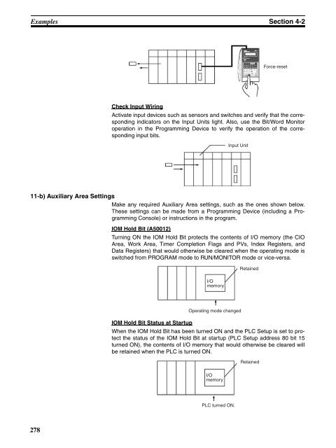
- Page 306 and 307: Examples Section 4-2 Note When devi
- Page 308 and 309: Examples Section 4-2 5. Clearing Me
- Page 310 and 311: Examples Section 4-2 5. Select Opti
- Page 312 and 313: Examples Section 4-2 7. PLC Setup S
- Page 316 and 317: Examples Section 4-2 11-c) Trial Op
- Page 318 and 319: Examples Section 4-2 12. Save and P
- Page 320 and 321: SECTION 5 Installation and Wiring T
- Page 322 and 323: Fail-safe Circuits Section 5-1 Inte
- Page 324 and 325: Installation Section 5-2 If a Progr
- Page 326 and 327: Installation Section 5-2 The mounti
- Page 328 and 329: Installation Section 5-2 5-2-4 Moun
- Page 330 and 331: Installation Section 5-2 Phillips s
- Page 332 and 333: Installation Section 5-2 DIN Track
- Page 334 and 335: Installation Section 5-2 Available
- Page 336 and 337: Installation Section 5-2 Total cabl
- Page 338 and 339: Installation Section 5-2 Mounting t
- Page 340 and 341: Installation Section 5-2 5-2-8 Inne
- Page 342 and 343: Wiring Section 5-3 C200HW-PA204 or
- Page 344 and 345: Wiring Section 5-3 Keep voltage flu
- Page 346 and 347: Wiring Section 5-3 IN0 IN(N) IN (N+
- Page 348 and 349: Wiring Section 5-3 C200HW-PD024/025
- Page 350 and 351: Wiring Section 5-3 CS-series PLC Ot
- Page 352 and 353: Wiring Section 5-3 7 mm max. 5-3-2
- Page 354 and 355: Wiring Section 5-3 Available Connec
- Page 356 and 357: Wiring Section 5-3 Note Double-chec
- Page 358 and 359: Wiring Section 5-3 2. Connecting to
- Page 360 and 361: Wiring Section 5-3 2 required C200H
- Page 362 and 363: Wiring Section 5-3 NPN current outp
- Page 364 and 365:
Wiring Section 5-3 Output Wiring Pr
- Page 366 and 367:
Wiring Section 5-3 Inductive Loads
- Page 368 and 369:
This section describes the settings
- Page 370 and 371:
DIP Switch Settings Section 6-1 Pin
- Page 372 and 373:
This section describes the settings
- Page 374 and 375:
PLC Setup Section 7-1 Cases when se
- Page 376 and 377:
PLC Setup Section 7-1 Mode Setting
- Page 378 and 379:
PLC Setup Section 7-1 Stop CPU on I
- Page 380 and 381:
PLC Setup Section 7-1 7-1-2-3 FB Co
- Page 382 and 383:
PLC Setup Section 7-1 Schedule Inte
- Page 384 and 385:
PLC Setup Section 7-1 7-1-2-6 Basic
- Page 386 and 387:
PLC Setup Section 7-1 Format: Stop
- Page 388 and 389:
PLC Setup Section 7-1 Baud Rate (bp
- Page 390 and 391:
PLC Setup Section 7-1 Start Code/En
- Page 392 and 393:
PLC Setup Section 7-1 Response Moni
- Page 394 and 395:
PLC Setup Section 7-1 NT Link Setti
- Page 396 and 397:
PLC Setup Section 7-1 Format: Parit
- Page 398 and 399:
PLC Setup Section 7-1 Set Time to A
- Page 400 and 401:
Explanations of PLC Setup Settings
- Page 402 and 403:
Explanations of PLC Setup Settings
- Page 404 and 405:
Explanations of PLC Setup Settings
- Page 406 and 407:
Explanations of PLC Setup Settings
- Page 408 and 409:
Explanations of PLC Setup Settings
- Page 410 and 411:
Explanations of PLC Setup Settings
- Page 412 and 413:
SECTION 8 I/O Allocations This sect
- Page 414 and 415:
I/O Allocations Section 8-1 Special
- Page 416 and 417:
I/O Allocations Section 8-1 I/O Tab
- Page 418 and 419:
I/O Allocation Methods Section 8-2
- Page 420 and 421:
I/O Allocation Methods Section 8-2
- Page 422 and 423:
I/O Allocation Methods Section 8-2
- Page 424 and 425:
I/O Allocation Methods Section 8-2
- Page 426 and 427:
Allocating First Words to Racks Sec
- Page 428 and 429:
Allocating First Words to Slots Sec
- Page 430 and 431:
Allocating First Words to Slots Sec
- Page 432 and 433:
Data Exchange with CPU Bus Units Se
- Page 434 and 435:
Data Exchange with CPU Bus Units Se
- Page 436 and 437:
This section describes the structur
- Page 438 and 439:
I/O Memory Areas Section 9-2 9-2 I/
- Page 440 and 441:
I/O Memory Areas Section 9-2 9-2-2
- Page 442 and 443:
I/O Memory Areas Section 9-2 3. The
- Page 444 and 445:
I/O Memory Areas Section 9-2 Auxili
- Page 446 and 447:
I/O Memory Areas Section 9-2 Index
- Page 448 and 449:
CIO Area Section 9-4 Restrictions T
- Page 450 and 451:
CIO Area Section 9-4 Note Immediate
- Page 452 and 453:
CIO Area Section 9-4 Ladder symbol
- Page 454 and 455:
C200H DeviceNet Area Section 9-5 9-
- Page 456 and 457:
CS-series DeviceNet Area Section 9-
- Page 458 and 459:
PLC Link Area Section 9-7 CIO Area
- Page 460 and 461:
CPU Bus Unit Area Section 9-9 4. PL
- Page 462 and 463:
Special I/O Unit Area Section 9-11
- Page 464 and 465:
SYSMAC BUS Area Section 9-12 9-12 S
- Page 466 and 467:
Work Area Section 9-14 I/O Terminal
- Page 468 and 469:
Auxiliary Area Section 9-16 Precaut
- Page 470 and 471:
Auxiliary Area Section 9-16 Special
- Page 472 and 473:
Auxiliary Area Section 9-16 Debuggi
- Page 474 and 475:
Auxiliary Area Section 9-16 Name Ad
- Page 476 and 477:
Auxiliary Area Section 9-16 Program
- Page 478 and 479:
Auxiliary Area Section 9-16 ■ Int
- Page 480 and 481:
Auxiliary Area Section 9-16 Name Ad
- Page 482 and 483:
Auxiliary Area Section 9-16 ■ Oth
- Page 484 and 485:
Auxiliary Area Section 9-16 ■ Pow
- Page 486 and 487:
Auxiliary Area Section 9-16 Informa
- Page 488 and 489:
Auxiliary Area Section 9-16 Informa
- Page 490 and 491:
Auxiliary Area Section 9-16 Instruc
- Page 492 and 493:
Timer Area Section 9-18 9-18 Timer
- Page 494 and 495:
Data Memory (DM) Area Section 9-20
- Page 496 and 497:
Extended Data Memory (EM) Area Sect
- Page 498 and 499:
Index Registers Section 9-22 9-22 I
- Page 500 and 501:
Index Registers Section 9-22 Index
- Page 502 and 503:
Index Registers Section 9-22 Limita
- Page 504 and 505:
Data Registers Section 9-23 Sharing
- Page 506 and 507:
Task Flags Section 9-24 9-24 Task F
- Page 508 and 509:
Condition Flags Section 9-25 to SEC
- Page 510 and 511:
Parameter Areas Section 9-27 9-27 P
- Page 512 and 513:
Parameter Areas Section 9-27 CS1 CP
- Page 514 and 515:
SECTION 10 CPU Unit Operation and t
- Page 516 and 517:
CPU Unit Operation Section 10-1 10-
- Page 518 and 519:
CPU Unit Operation Section 10-1 Pro
- Page 520 and 521:
CPU Unit Operation Section 10-1 Per
- Page 522 and 523:
CPU Unit Operating Modes Section 10
- Page 524 and 525:
Power OFF Operation Section 10-3 Po
- Page 526 and 527:
Power OFF Operation Section 10-3 10
- Page 528 and 529:
Computing the Cycle Time Section 10
- Page 530 and 531:
Computing the Cycle Time Section 10
- Page 532 and 533:
Computing the Cycle Time Section 10
- Page 534 and 535:
Computing the Cycle Time Section 10
- Page 536 and 537:
Computing the Cycle Time Section 10
- Page 538 and 539:
Computing the Cycle Time Section 10
- Page 540 and 541:
Computing the Cycle Time Section 10
- Page 542 and 543:
Computing the Cycle Time Section 10
- Page 544 and 545:
Computing the Cycle Time Section 10
- Page 546 and 547:
Instruction Execution Times and Num
- Page 548 and 549:
Instruction Execution Times and Num
- Page 550 and 551:
Instruction Execution Times and Num
- Page 552 and 553:
Instruction Execution Times and Num
- Page 554 and 555:
Instruction Execution Times and Num
- Page 556 and 557:
Instruction Execution Times and Num
- Page 558 and 559:
Instruction Execution Times and Num
- Page 560 and 561:
Instruction Execution Times and Num
- Page 562 and 563:
Instruction Execution Times and Num
- Page 564 and 565:
Instruction Execution Times and Num
- Page 566 and 567:
Instruction Execution Times and Num
- Page 568 and 569:
Instruction Execution Times and Num
- Page 570 and 571:
Instruction Execution Times and Num
- Page 572 and 573:
Instruction Execution Times and Num
- Page 574 and 575:
Instruction Execution Times and Num
- Page 576 and 577:
Instruction Execution Times and Num
- Page 578 and 579:
Instruction Execution Times and Num
- Page 580 and 581:
This section provides information o
- Page 582 and 583:
Error Processing Section 11-2 11-2
- Page 584 and 585:
Error Processing Section 11-2 11-2-
- Page 586 and 587:
Error Processing Section 11-2 Fatal
- Page 588 and 589:
Error Processing Section 11-2 CPU S
- Page 590 and 591:
Error Processing Section 11-2 Error
- Page 592 and 593:
Error Processing Section 11-2 Error
- Page 594 and 595:
Error Processing Section 11-2 Non-f
- Page 596 and 597:
Error Processing Section 11-2 Error
- Page 598 and 599:
Error Processing Section 11-2 Power
- Page 600 and 601:
Error Processing Section 11-2 11-2-
- Page 602 and 603:
Error Processing Section 11-2 11-2-
- Page 604 and 605:
Troubleshooting Racks and Units Sec
- Page 606 and 607:
Troubleshooting Racks and Units Sec
- Page 608 and 609:
This section provides inspection an
- Page 610 and 611:
Inspections Section 12-1 No. Item I
- Page 612 and 613:
Replacing User-serviceable Parts Se
- Page 614 and 615:
Replacing User-serviceable Parts Se
- Page 616 and 617:
Replacing User-serviceable Parts Se
- Page 618 and 619:
Replacing User-serviceable Parts Se
- Page 620 and 621:
Replacing User-serviceable Parts Se
- Page 622 and 623:
Input Units Appendix A Specificatio
- Page 624 and 625:
Specifications of Basic I/O Units a
- Page 626 and 627:
Specifications of Basic I/O Units a
- Page 628 and 629:
Specifications of Basic I/O Units a
- Page 630 and 631:
Specifications of Basic I/O Units a
- Page 632 and 633:
Specifications of Basic I/O Units a
- Page 634 and 635:
Specifications of Basic I/O Units a
- Page 636 and 637:
Specifications of Basic I/O Units a
- Page 638 and 639:
Specifications of Basic I/O Units a
- Page 640 and 641:
Specifications of Basic I/O Units a
- Page 642 and 643:
Specifications of Basic I/O Units a
- Page 644 and 645:
Specifications of Basic I/O Units a
- Page 646 and 647:
Specifications of Basic I/O Units a
- Page 648 and 649:
CN1 CN2 Specifications of Basic I/O
- Page 650 and 651:
Specifications of Basic I/O Units a
- Page 652 and 653:
Specifications of Basic I/O Units a
- Page 654 and 655:
Specifications of Basic I/O Units a
- Page 656 and 657:
Specifications of Basic I/O Units a
- Page 658 and 659:
Specifications of Basic I/O Units a
- Page 660 and 661:
Specifications of Basic I/O Units a
- Page 662 and 663:
Specifications of Basic I/O Units a
- Page 664 and 665:
Specifications of Basic I/O Units a
- Page 666 and 667:
Specifications of Basic I/O Units a
- Page 668 and 669:
Specifications of Basic I/O Units a
- Page 670 and 671:
Specifications of Basic I/O Units a
- Page 672 and 673:
Specifications of Basic I/O Units a
- Page 674 and 675:
Specifications of Basic I/O Units a
- Page 676 and 677:
Specifications of Basic I/O Units a
- Page 678 and 679:
Specifications of Basic I/O Units a
- Page 680 and 681:
Specifications of Basic I/O Units a
- Page 682 and 683:
Specifications of Basic I/O Units a
- Page 684 and 685:
Specifications of Basic I/O Units a
- Page 686 and 687:
Specifications of Basic I/O Units a
- Page 688 and 689:
Specifications of Basic I/O Units a
- Page 690 and 691:
Specifications of Basic I/O Units a
- Page 692 and 693:
Specifications of Basic I/O Units a
- Page 694 and 695:
Specifications of Basic I/O Units a
- Page 696 and 697:
Specifications of Basic I/O Units a
- Page 698 and 699:
Specifications of Basic I/O Units a
- Page 700 and 701:
Specifications of Basic I/O Units a
- Page 702 and 703:
Specifications of Basic I/O Units a
- Page 704 and 705:
Specifications of Basic I/O Units a
- Page 706 and 707:
Specifications of Basic I/O Units a
- Page 708 and 709:
Specifications of Basic I/O Units a
- Page 710 and 711:
Specifications of Basic I/O Units a
- Page 712 and 713:
Specifications of Basic I/O Units a
- Page 714 and 715:
Specifications of Basic I/O Units a
- Page 716 and 717:
Specifications of Basic I/O Units a
- Page 718 and 719:
Specifications of Basic I/O Units a
- Page 720 and 721:
Specifications of Basic I/O Units a
- Page 722 and 723:
Specifications of Basic I/O Units a
- Page 724 and 725:
Specifications of Basic I/O Units a
- Page 726 and 727:
Specifications of Basic I/O Units a
- Page 728 and 729:
Specifications of Basic I/O Units a
- Page 730 and 731:
Specifications of Basic I/O Units a
- Page 732 and 733:
Specifications of Basic I/O Units a
- Page 734 and 735:
Specifications of Basic I/O Units a
- Page 736 and 737:
Specifications of Basic I/O Units a
- Page 738 and 739:
Specifications of Basic I/O Units a
- Page 740 and 741:
Specifications of Basic I/O Units a
- Page 742 and 743:
Specifications of Basic I/O Units a
- Page 744 and 745:
Appendix B Auxiliary Area Note The
- Page 746 and 747:
Auxiliary Area Appendix B Address N
- Page 748 and 749:
Auxiliary Area Appendix B Address N
- Page 750 and 751:
Auxiliary Area Appendix B Address N
- Page 752 and 753:
Auxiliary Area Appendix B Address N
- Page 754 and 755:
Auxiliary Area Appendix B Address N
- Page 756 and 757:
Auxiliary Area Appendix B Address N
- Page 758 and 759:
Auxiliary Area Appendix B Address N
- Page 760 and 761:
Auxiliary Area Appendix B Address N
- Page 762 and 763:
Auxiliary Area Appendix B Address N
- Page 764 and 765:
Auxiliary Area Appendix B Address N
- Page 766 and 767:
Auxiliary Area Appendix B Address N
- Page 768 and 769:
Auxiliary Area Appendix B Addresses
- Page 770 and 771:
Auxiliary Area Appendix B Addresses
- Page 772 and 773:
Auxiliary Area Appendix B Addresses
- Page 774 and 775:
Auxiliary Area Appendix B Addresses
- Page 776 and 777:
Auxiliary Area Appendix B Addresses
- Page 778 and 779:
Auxiliary Area Appendix B The follo
- Page 780 and 781:
Auxiliary Area Appendix B A300: Err
- Page 782 and 783:
Appendix C Memory Map of PLC Memory
- Page 784 and 785:
Appendix D PLC Setup Coding Sheets
- Page 786 and 787:
PLC Setup Coding Sheets for Program
- Page 788 and 789:
PLC Setup Coding Sheets for Program
- Page 790 and 791:
PLC Setup Coding Sheets for Program
- Page 792 and 793:
PLC Setup Coding Sheets for Program
- Page 794 and 795:
PLC Setup Coding Sheets for Program
- Page 796 and 797:
Connection Examples Appendix E Conn
- Page 798 and 799:
Connecting to the RS-232C Port on t
- Page 800 and 801:
Connecting to the RS-232C Port on t
- Page 802 and 803:
Connecting to the RS-232C Port on t
- Page 804 and 805:
Appendix F Restrictions in Using C2
- Page 806 and 807:
Restrictions in Using C200H Special
- Page 808 and 809:
Restrictions in Using C200H Special
- Page 810 and 811:
Appendix G CJ1W-CIF11 RS-422A Conve
- Page 812 and 813:
CJ1W-CIF11 RS-422A Converter Append
- Page 814 and 815:
CJ1W-CIF11 RS-422A Converter Append
- Page 816 and 817:
Numerics 24-V DC output power, 307
- Page 818 and 819:
data shift instructions execution t
- Page 820 and 821:
error information, 394 I/O Terminal
- Page 822 and 823:
settings, 350 peripheral devices Se
- Page 824 and 825:
C200H-MD115 (static), 695 C200H-MD2
- Page 826 and 827:
Revision History A manual revision
- Page 828 and 829:
Revision History Revision code Date
- Page 830 and 831:
Revision History Revision code Date
- Page 832 and 833:
OMRON Corporation Control Devices D