
You also want an ePaper? Increase the reach of your titles
YUMPU automatically turns print PDFs into web optimized ePapers that Google loves.
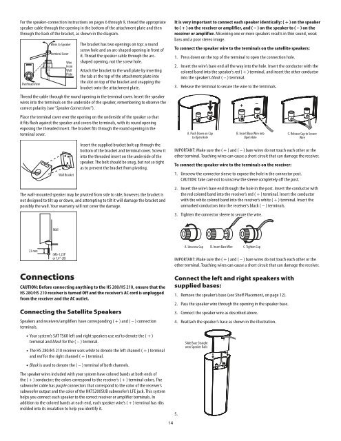
For the speaker-connection instructions on pages 6 through 9, thread the appropriate<br />
speaker cable through the opening in the bottom of the attachment plate and then<br />
through the back of the bracket, as shown in the diagram<br />
Overhead View<br />
Wires to Speaker<br />
Terminal Cover<br />
Wire<br />
From<br />
Wall<br />
Plate<br />
Connections<br />
CAUTION: Before connecting anything to the <strong>HS</strong> <strong>280</strong>/<strong>HS</strong> <strong>210</strong>, ensure that the<br />
<strong>HS</strong> <strong>280</strong>/<strong>HS</strong> <strong>210</strong> receiver is turned Off and the receiver’s AC cord is unplugged<br />
from the receiver and the AC outlet.<br />
Connecting the Satellite Speakers<br />
The bracket has two openings on top: a round<br />
screw hole and an arc-shaped opening in front of<br />
it Thread the speaker cable through the arcshaped<br />
opening, not the screw hole<br />
Attach the bracket to the wall plate by inserting<br />
the tab at the top of the attachment plate into<br />
the slot on top of the bracket and snapping the<br />
bracket onto the attachment plate<br />
Thread the cable through the round opening in the terminal cover Insert the speaker<br />
wires into the terminals on the underside of the speaker, remembering to observe the<br />
correct polarity (see “Speaker Connections”)<br />
Place the terminal cover over the opening on the underside of the speaker so that<br />
it fits flush against the speaker and covers the terminals, with its round opening<br />
exposing the threaded insert The bracket fits through the round opening in the<br />
terminal cover<br />
Wall Bracket<br />
Insert the supplied bracket bolt up through the<br />
bottom of the bracket and terminal cover Screw it<br />
into the threaded insert on the underside of the<br />
speaker The bolt should be snug, but not so tight<br />
as to prevent the bracket from pivoting<br />
The wall-mounted speaker may be pivoted from side to side; however, the bracket is<br />
not designed to tilt up or down, and attempting to tilt it will damage the bracket and<br />
possibly the wall Your warranty will not cover the damage<br />
23 mm<br />
Wall<br />
(M6-1 25P<br />
or 1 4"-20)<br />
Speakers and receivers/amplifiers have corresponding ( + ) and ( – ) connection<br />
terminals<br />
• Your system’s SAT TS60 left and right speakers use red to denote the ( + )<br />
terminal and black for the ( – ) terminal<br />
• The <strong>HS</strong> <strong>280</strong>/<strong>HS</strong> <strong>210</strong> receiver uses white to denote the left channel ( + ) terminal<br />
and red for the right channel ( + ) terminal<br />
• Black is used to denote the ( – ) terminal of both channels<br />
The speaker wires included with your system have colored bands at both ends of<br />
the ( + ) conductor; the colors correspond to the receiver’s ( + ) terminal colors The<br />
subwoofer cable has purple connectors that correspond to the color of the receiver’s<br />
subwoofer output and the color of the HKTS200SUB subwoofer’s LFE jack This system<br />
helps you connect each speaker to the correct receiver or amplifier terminals In<br />
addition to the colored bands at each end, each speaker wire’s ( + ) terminal has ribs<br />
molded into its insulation to help you identify it<br />
14<br />
It is very important to connect each speaker identically: ( + ) on the speaker<br />
to ( + ) on the receiver or amplifier, and ( – ) on the speaker to ( – ) on the<br />
receiver or amplifier. Miswiring one or more speakers results in thin sound, weak<br />
bass and a poor stereo image<br />
To connect the speaker wire to the terminals on the satellite speakers:<br />
1<br />
Press down on the top of the terminal to open the connection hole<br />
2 Insert the wire’s bare end all the way into the hole Insert the conductor with the<br />
colored band into the speaker’s red ( + ) terminal, and insert the other conductor<br />
into the speaker’s black ( – ) terminal<br />
3<br />
Release the terminal to secure the wire to the terminals<br />
A Push Down on Cap<br />
to Open Hole<br />
+<br />
–<br />
B Insert Base Wire into<br />
Open Hole<br />
C Release Cap to Secure<br />
Wire<br />
IMPORTANT: Make sure the ( + ) and ( – ) bare wires do not touch each other or the<br />
other terminal Touching wires can cause a short circuit that can damage the receiver<br />
To connect the speaker wire to the terminals on the receiver:<br />
1<br />
Unscrew the connector sleeve to expose the hole in the connector post<br />
CAUTION: Take care not to unscrew the sleeve completely off the post<br />
2 Insert the wire’s bare end through the hole in the post Insert the conductor with<br />
the red colored band into the receiver’s red ( + ) terminal Insert the conductor<br />
with the white colored band into the receiver’s white ( + ) terminal Insert the<br />
unmarked conductors into the receiver’s black ( – ) terminals<br />
3<br />
Tighten the connector sleeve to secure the wire<br />
A Unscrew Cap B Insert Bare Wire C Tighten Cap<br />
IMPORTANT: Make sure the ( + ) and ( – ) bare wires do not touch each other or the<br />
other terminal Touching wires can cause a short circuit that can damage the receiver<br />
Connect the left and right speakers with<br />
supplied bases:<br />
1 Remove the speaker’s base (see Shelf Placement, on page 12)<br />
2<br />
Pass the speaker wire through the opening in the speaker base<br />
3 Connect the speaker wire as described above<br />
4<br />
5<br />
Reattach the speaker’s base as shown in the illustration<br />
Slide Base Straight<br />
onto Speaker Rails