Create successful ePaper yourself
Turn your PDF publications into a flip-book with our unique Google optimized e-Paper software.
Coaxial 1/Coaxial 2 In and Optical 1/Optical 2 In: If you have an audio-only<br />
digital source component (such as a CD changer or video game), you can connect it to<br />
one of these inputs, as shown in the illustration under Connecting Audio Sources, on<br />
page 16 When using the Optical 1 and Optical 2 digital connections, gently push the<br />
cable connector through the panel connector’s built-in shutter until it is firmly seated<br />
in the connector<br />
NOTE: Use only one type of digital connection for each source component<br />
Connecting an Audio Recorder<br />
Line Out: If you have an analog recorder such as a cassette deck, connect its record<br />
inputs to the <strong>HS</strong> <strong>280</strong>/<strong>HS</strong> <strong>210</strong>’s Line Out jacks NOTE: You should connect the recorder’s<br />
analog outputs to the <strong>HS</strong> <strong>280</strong>/<strong>HS</strong> <strong>210</strong>’s Line 1 In or Line 2 In jacks<br />
Coaxial Out: If you have a digital recorder such as a CD-R or MiniDisc, connect its<br />
coaxial input to the <strong>HS</strong> <strong>280</strong>/<strong>HS</strong> <strong>210</strong>’s Coaxial Out jack<br />
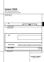
Connecting to a Local Area Network (LAN)<br />
Use a CAT 5 RJ45 network cable (not supplied) to connect the <strong>HS</strong> <strong>280</strong>/<strong>HS</strong> <strong>210</strong>’s<br />
Ethernet port directly to a network router, a network switch or an Ethernet network<br />
wall jack<br />
NOTE: For the <strong>HS</strong> <strong>280</strong>/<strong>HS</strong> <strong>210</strong> to interface with a networked computer, that computer<br />
must be running UPnP (Universal Plug and Play)-compliant media software such as<br />
Windows Media Player, MediaLink or EyeConnect<br />
Laptop<br />
Computer<br />
Receiver<br />
CAT 5 RJ45 Cable<br />
(not supplied)<br />
Desktop<br />
Computer<br />
Network<br />
Modem<br />
Local-Area<br />
Network (LAN)<br />
IMPORTANT: The <strong>HS</strong> <strong>280</strong>/<strong>HS</strong> <strong>210</strong>’s Ethernet connection will not support a proxy<br />
network<br />
Connecting the AC Power<br />
The <strong>HS</strong> <strong>280</strong>/<strong>HS</strong> <strong>210</strong> receiver comes with a detachable AC power cord This type of cord<br />
makes it easier for you to install and connect all other system wiring to the receiver’s<br />
rear panel The HKTS200SUB subwoofer has a non-detachable power cord Plug the<br />
subwoofer’s power cord into a working, unswitched AC outlet<br />
NOTES:<br />
• The power requirement for the <strong>HS</strong> <strong>280</strong>/<strong>HS</strong> <strong>210</strong> receiver is 100–240V AC ~<br />
50/60Hz, 300W The power requirement for the HKTS200SUB subwoofer is<br />
220–240V AC ~ 50/60Hz, 200W<br />
• Connecting to a power source other than the ones listed above may damage the<br />
receiver or subwoofer, or cause abnormal operation<br />
• Before connecting the AC power cords to a wall outlet, confirm that all of the<br />
speaker connections, video connections and audio-component connections have<br />
been made correctly<br />
17<br />
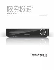
• Connect the female end of the receiver’s detachable power cord to the receiver’s<br />
AC Power Input connector Plug the other end into a working, unswitched AC<br />
outlet<br />
•<br />
•<br />
Power Chord Cord<br />
(female end)<br />
The receiver’s Power Indicator will turn red, indicating that the receiver is in the<br />
standby mode<br />
The subwoofer’s LED will not illuminate until it receives a turn-on signal See<br />
Subwoofer Controls and Connections, on page 9, for details<br />
Preparing the Remote Control<br />
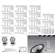
Installing the Batteries<br />
The <strong>HS</strong> <strong>280</strong>/<strong>HS</strong> <strong>210</strong>’s system remote control uses three AAA batteries (supplied)<br />
Insert the batteries as shown in the illustration, making sure to observe the correct<br />
polarity<br />
A Remove<br />
Cover<br />
B Insert 3 AAA<br />
Batteries<br />
– + –<br />
–<br />
+ +<br />
Using the Remote Control<br />
C Replace Cover<br />
When using the remote, remember to aim it toward the <strong>HS</strong> <strong>280</strong>/<strong>HS</strong> <strong>210</strong>’s front panel<br />
Make sure that no objects, such as furniture, block the remote’s view of the receiver<br />
Bright lights, fluorescent lights, and plasma-video displays may interfere with the<br />
function of the remote<br />
• The remote has a range of about 20 feet (6 1m), depending on the lighting<br />
conditions<br />
• You can use the remote at an angle of up to 30° to either side of the <strong>HS</strong> <strong>280</strong>/<br />
<strong>HS</strong> <strong>210</strong><br />
• If the remote seems to operate intermittently, or if pressing a button on the<br />
remote does not cause one of the source buttons to illuminate, make sure that the<br />
batteries are inserted correctly, or replace all three batteries with new ones<br />
Programming the Remote Control<br />
You can also program the remote so it will control two additional components –<br />
typically your TV and a video source such as a satellite or cable receiver – in addition<br />
to controlling the <strong>HS</strong> <strong>280</strong>/<strong>HS</strong> <strong>210</strong> receiver<br />
To control the TV and video component, you can teach codes from the TV and videocomponent<br />
remotes onto the <strong>HS</strong> <strong>280</strong>/<strong>HS</strong> <strong>210</strong> remote buttons shown shaded in the<br />
following illustration:<br />
ENGLISH