Operator's Manual 10 in. COMPOUND MITER SAW WITH ... - Sears
Operator's Manual 10 in. COMPOUND MITER SAW WITH ... - Sears
Operator's Manual 10 in. COMPOUND MITER SAW WITH ... - Sears

You also want an ePaper? Increase the reach of your titles
YUMPU automatically turns print PDFs into web optimized ePapers that Google loves.
ASSEMBLY AND ADJUSTMENTS<br />
ASSEMBLY INSTRUCTIONS<br />
! WARNING<br />
To avoid <strong>in</strong>jury, do not connect this miter<br />
saw to the power source until it is completely<br />
assembled and adjusted and you have read<br />
and understood this Operator’s <strong>Manual</strong>.<br />
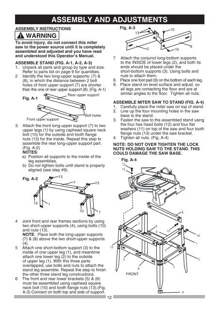
ASSEMBLE STAND (FIG. A-1, A-2, A-3)<br />
1. Unpack all parts and group by type and size.<br />
Refer to parts list on page 9 for quantities.<br />
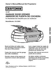
2 Identify the two long-upper supports: (7) &<br />
(8), <strong>in</strong> which the distance between 2 bolt<br />
holes of front upper support (7) are shorter<br />
than the one of rear upper support (8). (Fig. A-1)<br />
Rear upper support<br />
Fig. A-1<br />
Bolt holes<br />
Front upper support<br />
3. Attach the front long-upper support (7) to two<br />
upper legs (1) by us<strong>in</strong>g caphead square neck<br />
bolt (<strong>10</strong>) for the outside and tooth flange<br />
nuts (13) for the <strong>in</strong>side. Repeat this step to<br />
assemble the rear long-upper support part.<br />
(Fig. A-2)<br />
NOTES:<br />
a) Position all supports to the <strong>in</strong>side of the<br />
leg assemblies.<br />
b) Do not tighten bolts until stand is properly<br />
aligned (see step #9).<br />
Fig. A-2<br />
<strong>10</strong><br />
1<br />
13<br />
4 Jo<strong>in</strong>t front and rear frames sections by us<strong>in</strong>g<br />
two short-upper supports (4), us<strong>in</strong>g bolts (<strong>10</strong>)<br />
and nuts (13).<br />
NOTE: Place both the long-upper supports<br />
(7) & (8) above the two short-upper supports<br />
(4).<br />
5 Attach one short-bottom support (3) to the <br />
<strong>in</strong>side of one upper leg (1), and meantime<br />
attach one lower leg (2) to the outside<br />
of upper leg (1). With this three parts<br />
overlapped, use bolts and nuts to attach the<br />
stand leg assemble. Repeat the step to f<strong>in</strong>ish<br />
the other three stand leg constructions.<br />
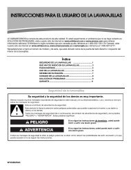
6 The front and rear lower brackets (5) & (6)<br />
must be assembled us<strong>in</strong>g caphead square<br />
neck bolt (<strong>10</strong>) and tooth flange nuts (13).(Fig.<br />
A-3) Connect on both top and side of support.<br />
12<br />
7<br />
<strong>10</strong><br />
13<br />
1<br />
Fig. A-3<br />
13<br />
5<br />
7 Attach the conjunct long-bottom supports<br />
to the INSIDE of lower legs (2), and both its<br />
ends should be placed under the<br />
short-bottom supports (3). Us<strong>in</strong>g bolts and<br />
nuts to attach them.<br />
8. Place one foot pad (9) on the bottom of each leg.<br />
9. Place stand on level surface and adjust, so<br />
all legs are contact<strong>in</strong>g the floor and are at<br />
similar angles to the floor. Tighten all nuts.<br />
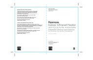
ASSEMBLE <strong>MITER</strong> <strong>SAW</strong> TO STAND (FIG. A-4)<br />
1. Carefully place the miter saw on top of stand.<br />
2. L<strong>in</strong>e up the four mount<strong>in</strong>g holes <strong>in</strong> the saw<br />
base to the stand.<br />
3. Fasten the saw to the assembled stand us<strong>in</strong>g<br />
the four hex head bolts (12) and four flat<br />
washers (11) on top of the saw and four tooth<br />
flange nuts (13) under the saw bracket.<br />
4. Tighten all nuts. (Fig. A-4)<br />
NOTE: DO NOT OVER TIGHTEN THE LOCK<br />
NUTS HOLDING <strong>SAW</strong> TO THE STAND. THIS<br />
COULD DAMAGE THE <strong>SAW</strong> BASE.<br />
Fig. A-4<br />
<br />
11<br />
<br />
<br />
<br />
FRONT<br />
<br />
<br />
<br />
<br />
<strong>10</strong><br />
<br />
<strong>10</strong><br />
<br />
<br />
6