Operator's Manual 10 in. COMPOUND MITER SAW WITH ... - Sears
Operator's Manual 10 in. COMPOUND MITER SAW WITH ... - Sears
Operator's Manual 10 in. COMPOUND MITER SAW WITH ... - Sears

You also want an ePaper? Increase the reach of your titles
YUMPU automatically turns print PDFs into web optimized ePapers that Google loves.
ADJUSTMENT INSTRUCTIONS<br />
!<br />
WARNING<br />
To avoid <strong>in</strong>jury from an accidental start, make<br />
sure the switch is <strong>in</strong> the OFF position and the<br />
plug is not connected to the power source<br />
outlet.<br />
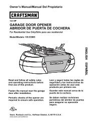
ADJUSTING FENCE SQUARENESS (FIG. L)<br />
1. Loosen the three fence lock<strong>in</strong>g bolts(1).<br />
2. Lower the cutt<strong>in</strong>g arm and lock <strong>in</strong> position.<br />
3. Us<strong>in</strong>g a square, lay the heel of the square<br />
aga<strong>in</strong>st the blade, and the rule agaist the<br />
fence (2) as shown.<br />
Check to see if the fence is 90° to the blade.<br />
4. If not, adjust fence 90° to the blade and<br />
tighten the fence lock<strong>in</strong>g bolts.<br />
CAUTION: If the saw has not been used<br />
recently, recheck blade squareness to the<br />
fence and readjust if needed.<br />
5. After fence has been aligned, us<strong>in</strong>g a scrap<br />
piece of wood, make a cut at 90 o then<br />
check squareness on the piece. Readjust if<br />
necessary.<br />
Fig. L<br />
1 2 1<br />
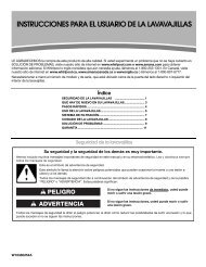
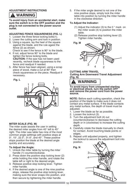
<strong>MITER</strong> SCALE (FIG. M)<br />
The miter scale assists the user <strong>in</strong> sett<strong>in</strong>g<br />
the desired miter angles from 45° left to 45°<br />
right. The miter saw table has n<strong>in</strong>e of the most<br />
common angle settt<strong>in</strong>gs with positive stops at<br />
0°, 15°, 22.5°, 31.6°, and 45°. These positive<br />
stops position the blade at the desired angle<br />
quickly and accurately.<br />
To Adjust the Angle:<br />
1. Unlock the miter table by turn<strong>in</strong>g the miter<br />
handle (1) counterclockwise.<br />
2. Press down the positive stop lock<strong>in</strong>g lever (2)<br />
while hold<strong>in</strong>g the miter handle, and rotate the<br />
table left or right to the desired angle.<br />
3. Release positive stop lock<strong>in</strong>g lever. Tighten<br />
miter handle.<br />
4. If the desired angle is one of the n<strong>in</strong>e positive<br />
stops, release the positive stop lock<strong>in</strong>g lever,<br />
mak<strong>in</strong>g sure the lever snaps <strong>in</strong>to position, and<br />
then secure by tighten<strong>in</strong>g the miter handle.<br />
16<br />
5. If the miter angle desired is not one of the<br />
n<strong>in</strong>e positive stops, simply lock the miter<br />
table <strong>in</strong>to position by turn<strong>in</strong>g the miter handle<br />
<strong>in</strong> the clockwise direction.<br />
To Adjust the Indicator:<br />
(1) Adjust the <strong>in</strong>dicator (3) to the 0 ° mark on<br />
the miter scale (4) to position the miter<br />
table.<br />
(2) Release positive stop lock<strong>in</strong>g lever (2).<br />
Tighten miter handle.<br />
Fig. M<br />
3<br />
4 2<br />
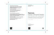
CUTTING ARM TRAVEL<br />
Cutt<strong>in</strong>g Arm Downward Travel Adjustment<br />
(Fig. N)<br />
! WARNING<br />
To avoid <strong>in</strong>jury from unexpected start<strong>in</strong>g<br />
or electrical shock, turn the switch OFF<br />
and remove the power cord from the power<br />
source.<br />
NOTE: Before each cutt<strong>in</strong>g operation, check the<br />
position of the blade to make sure it does not<br />
contact any metal surface. If the blade contacts<br />
any metal surface, the depth of travel must be<br />
adjusted.<br />
1. Lower the blade as far as possible.<br />
2. Loosen the locknut (3).<br />
3. Turn the adjustment bolt (4) out<br />
(counterclockwise) to decrease the cutt<strong>in</strong>g<br />
depth or <strong>in</strong> (clockwise) to <strong>in</strong>crease the cutt<strong>in</strong>g<br />
depth.<br />
4. Carefully rotate the blade manually to check<br />
for contact. Avoid touch<strong>in</strong>g blade po<strong>in</strong>ts or<br />
edges.<br />
5. Repeat until adjusted properly, and tighten<br />
the locknut to secure the adjustment bolt <strong>in</strong>to<br />
position.<br />
Fig. N<br />
3<br />
4<br />
1