Operator's Manual 10 in. COMPOUND MITER SAW WITH ... - Sears
Operator's Manual 10 in. COMPOUND MITER SAW WITH ... - Sears
Operator's Manual 10 in. COMPOUND MITER SAW WITH ... - Sears

Create successful ePaper yourself
Turn your PDF publications into a flip-book with our unique Google optimized e-Paper software.
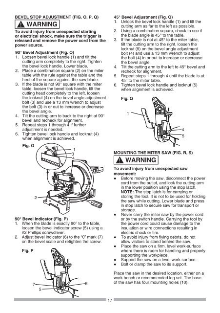
BEVEL STOP ADJUSTMENT (FIG. O, P, Q)<br />
!<br />
WARNING<br />
To avoid <strong>in</strong>jury from unexpected start<strong>in</strong>g<br />
or electrical shock, make sure the trigger is<br />
released and remove the power cord from the<br />
power source.<br />
90° Bevel Adjustment (Fig. O)<br />
1. Loosen bevel lock handle (1) and tilt the<br />
cutt<strong>in</strong>g arm completely to the right. Tighten<br />
the bevel lock handle. Lower blade.<br />
2. Place a comb<strong>in</strong>ation square (2) on the miter<br />
table with the rule aga<strong>in</strong>st the table and the<br />
heel of the square aga<strong>in</strong>st the saw blade.<br />
3. If the blade is not 90° square with the miter<br />
table, loosen the bevel lock handle, tilt the<br />
cutt<strong>in</strong>g head completely to the left, loosen<br />
the locknut (4) on the bevel angle adjustment<br />
bolt (3) and use a 13 mm wrench to adjust<br />
the bolt (3) <strong>in</strong> or out to <strong>in</strong>crease or decrease<br />
the bevel angle.<br />
4. Tilt the cutt<strong>in</strong>g arm to back to the right at 90°<br />
bevel and recheck for alignment.<br />
5. Repeat steps 1 through 4 if further<br />
adjustment is needed.<br />
6. Tighten bevel lock handle and locknut (4)<br />
when alignment is achieved.<br />
Fig. O<br />
1<br />
3<br />
4<br />
2<br />
90° Bevel Indicator (Fig. P)<br />
1. When the blade is exactly 90° to the table,<br />
loosen the bevel <strong>in</strong>dicator screw (5) us<strong>in</strong>g a<br />
#2 Phillips screwdriver.<br />
2. Adjust bevel <strong>in</strong>dicator (6) to the “0” mark (7)<br />
on the bevel scale and retighten the screw.<br />
Fig. P<br />
7<br />
5<br />
6<br />
17<br />
45° Bevel Adjustment (Fig. Q)<br />
1. Unlock the bevel lock handle (1) and tilt the<br />
cutt<strong>in</strong>g arm as far to the left as possible.<br />
2. Us<strong>in</strong>g a comb<strong>in</strong>ation square, check to see if<br />
the blade angle is 45° to the table.<br />
3. If the blade is not at 45° to the miter table,<br />
tilt the cutt<strong>in</strong>g arm to the right, loosen the<br />
locknut (5) on the bevel angle adjustment<br />
bolt (4) and use a 13 mm wrench to adjust<br />
the bolt (4) <strong>in</strong> or out to <strong>in</strong>crease or decrease<br />
the bevel angle.<br />
4. Tilt the cutt<strong>in</strong>g arm to the left to 45° bevel and<br />
recheck for alignment.<br />
5. Repeat steps 1 through 4 until the blade is at<br />
45° to the miter table.<br />
6. Tighten bevel lock handle and locknut (5)<br />
when alignment is achieved.<br />
Fig. Q<br />
1<br />
4<br />
5<br />
MOUNTING THE <strong>MITER</strong> <strong>SAW</strong> (FIG. R, S)<br />
!<br />
WARNING<br />
To avoid <strong>in</strong>jury from unexpected saw<br />
movement:<br />
● Before mov<strong>in</strong>g the saw, disconnect the power<br />
cord from the outlet, and lock the cutt<strong>in</strong>g arm<br />
<strong>in</strong> the lower position us<strong>in</strong>g the stop latch.<br />
NOTE: The stop latch is for carry<strong>in</strong>g or<br />
stor<strong>in</strong>g the tool. It is not to be used for hold<strong>in</strong>g<br />
the saw while cutt<strong>in</strong>g. Lower blade and press<br />
<strong>in</strong> stop latch to secure saw for transport or<br />
storage.<br />
● Never carry the miter saw by the power cord<br />
or by the switch handle. Carry<strong>in</strong>g the tool by<br />
the power cord could cause damage to the<br />
<strong>in</strong>sulation or wire connections result<strong>in</strong>g <strong>in</strong><br />
electric shock or fire.<br />
● To avoid <strong>in</strong>jury from fly<strong>in</strong>g debris, do not<br />
allow visitors to stand beh<strong>in</strong>d the saw.<br />
● Place the saw on a firm, level work-surface<br />
where there is room for handl<strong>in</strong>g and properly<br />
support<strong>in</strong>g the workpiece.<br />
● Support the saw on a level work surface.<br />
● Bolt or clamp the saw to its support.<br />
Place the saw <strong>in</strong> the desired location, either on a<br />
work bench or recommended leg set. The base<br />
of the saw has four mount<strong>in</strong>g holes (<strong>10</strong>).