Test Plan for Optical Grooming Switches - Light Reading
Test Plan for Optical Grooming Switches - Light Reading
Test Plan for Optical Grooming Switches - Light Reading

Create successful ePaper yourself
Turn your PDF publications into a flip-book with our unique Google optimized e-Paper software.
<strong>Test</strong> Specification<br />
Issue 2.1 (25 June 2002)<br />
<strong>Test</strong> <strong>Plan</strong> <strong>for</strong> <strong>Optical</strong> <strong>Grooming</strong><br />
<strong>Switches</strong>
Contents<br />
<strong>Test</strong> <strong>Plan</strong> <strong>for</strong> <strong>Optical</strong> <strong>Grooming</strong> <strong>Switches</strong><br />
Document history 4<br />
Introduction 5<br />
<strong>Test</strong> Equipment 5<br />
<strong>Test</strong> Entry Criteria 7<br />
<strong>Test</strong> Network Configuration 8<br />
Configuration B 13<br />
<strong>Test</strong> Methodology 14<br />
<strong>Test</strong> cases, Configuration A: Mesh Restoration and various protection schemes. 17<br />
BLOCK 1. Trail creation and support <strong>for</strong> required interface and granularities 17<br />
BLOCK 2. Mesh restoration and various protection mechanisms. 21<br />
BLOCK 3. Trail reservation and Inverse Multiplexing. 27<br />
BLOCK 4. Management Bytes Path monitoring 30<br />
BLOCK 5. Ethernet Service provisioning using 10/100 BaseT or GigE. 32<br />
BLOCK 6. Multiple payloads trunk filling, grooming and Virtual Concatenation 33<br />
BLOCK 7. SONET to SDH conversion and High Order SONET STS-1 to Lower Order SDH AU3 35<br />
BLOCK 8. Tandem Connection Monitoring 36<br />
BLOCK 9. Transparency of vendors system to SONET / SDH overhead bytes. TCA53 to TCA57 39<br />
BLOCK 10. Alarm reporting – including “flapping” alarms 41<br />
BLOCK 11.DCN failure node isolation 42<br />
BLOCK 12. Management and removal of cards 44<br />
BLOCK 13. Node Failure and 1:N transponder protection on WDM system 46<br />
<strong>Test</strong> cases, Configuration B: bi-directional Line Switched Rings (BLSR's) 47<br />
BLOCK 14. OC-48 BLSR tests 47<br />
BLOCK 15. STM-64 MS-SPRING tests 51<br />
BLOCK 16. <strong>Optical</strong> Interface <strong>Test</strong>ing 53<br />
BLOCK 17 . Software upgrades 54<br />
Appendix A. Evaluation agreement to be signed 56<br />
2
Published by BTexact Technologies –<br />
a division of British Telecommunications plc<br />
Adastral Park, Martlesham<br />
Ipswich IP5 3RE, UK<br />
Offices and laboratories worldwide<br />
Email<br />
btexact@bt.com<br />
Freephone<br />
0800 169 1689 (UK only)<br />
Phone<br />
+44 (0)1473 607080<br />
Fax<br />
+44 (0)1473 607700<br />
© British Telecommunications plc, 2002.<br />
Registered office: 81 Newgate Street, London EC1A 7AJ.<br />
Registered in England, number 1800000.<br />
All rights reserved.<br />
Permission is given <strong>for</strong> this publication to be reproduced provided it is<br />
reproduced in its entirety and that a similar condition, including these<br />
conditions, is included in the reproduction. Reproduction of parts of this<br />
publication is permitted provided the source is clearly acknowledged. For<br />
further details, please contact the publisher.<br />
BTexact Technologies maintains that all reasonable care and skill has been<br />
used in the compilation of this publication. However, BTexact<br />
Technologies shall not be under any liability <strong>for</strong> loss or damage (including<br />
consequential loss) whatsoever or howsoever arising as a result of the<br />
use of this publication by the reader, his servants, agents or any third<br />
party.<br />
All third-party trademarks are hereby acknowledged.<br />
<strong>Test</strong> <strong>Plan</strong> <strong>for</strong> <strong>Optical</strong> <strong>Grooming</strong> <strong>Switches</strong><br />
3
Document history<br />
<strong>Test</strong> <strong>Plan</strong> <strong>for</strong> <strong>Optical</strong> <strong>Grooming</strong> <strong>Switches</strong><br />
Issue<br />
number<br />
Date Changes<br />
1.0 27 May<br />
2002<br />
Initial issue<br />
1.1 28 May Trivial changes.<br />
2002 More reference made to specific Agilent test equipment<br />
“Draft <strong>for</strong> comment” added to front sheet<br />
Issue 2.0 21 June<br />
2002<br />
Incorporated comments from vendors<br />
Issue 2.1 25 June<br />
2002<br />
Minor change to ethernet tests<br />
4
Introduction<br />
<strong>Test</strong> <strong>Plan</strong> <strong>for</strong> <strong>Optical</strong> <strong>Grooming</strong> <strong>Switches</strong><br />
BTexact Technologies are to per<strong>for</strong>m 1 , on behalf of <strong>Light</strong> <strong>Reading</strong>, a series of evaluations of<br />
commercially available optical sub-wavelength grooming switches. The first step was <strong>for</strong><br />
BTexact Technologies to write a white paper - “Carrier requirements of optical grooming<br />
switches” - to be published by <strong>Light</strong> <strong>Reading</strong>. 2 This test plan is the next stage in the process.<br />
It defines a series of tests, which will be used by BTexact Technologies to test the optical<br />
grooming switches of participating vendors against the carrier requirements document 1 .<br />
This report has been prepared by BTexact Technologies. The requirements contained herein<br />
do not necessarily reflect the specific requirements of any other part of the BT Group.<br />
BTexact Technologies is British Telecommunications’ advanced research and technology<br />
business created to allow services hitherto reserved <strong>for</strong> the BT Group to be made available to<br />
external customers.<br />
All tests will be per<strong>for</strong>med in BTexact Technologies’ laboratories at Adastral Park 3 , near<br />
Ipswich, UK.<br />
As the technical design authority <strong>for</strong> many of the networks and services operated by BT, we<br />
have a wealth of knowledge in product testing and evaluation, built up over a number of<br />
years. Our experience has allowed us to develop test and evaluation methodologies that have<br />
been proven by subsequent feedback from deployed networks. As you would expect, we also<br />
have an in-depth understanding of the specific needs of carriers that, when combined with the<br />
state-of-the-art test equipment we have available, allows us to offer our customers both<br />
accurate, well-planned testing and speed of implementation.<br />
This test plan attempts to test equipment against as many as possible of the ideal requirements<br />
which were identified in “Carrier requirements of optical grooming switches”. 4 However<br />
there are some important requirements important requirements which it is not practical to<br />
explicitly test within a relatively small test network and within the short testing window<br />
available. These requirements will there<strong>for</strong>e be assessed by BTexact Technologies via a<br />
paper audit, enhanced by referring to the equipment in the laboratory as required. Specific<br />
examples of these requirements are:-<br />
-switch scalability (i.e. footprint proportional to capacity with hitless upgrades)<br />
-power requirements<br />
-fibre management<br />
<strong>Test</strong> Equipment<br />
SONET/SDH test equipment <strong>for</strong> the tests will be provided by Agilent Technologies as<br />
follows:-<br />
1x Omniber OTN - J7230A - 10G + G.709 SONET/SDH <strong>Test</strong>er 5<br />
1x J2127A - 10G SONET/SDH <strong>Test</strong>er 6<br />
1 http://www.lightreading.com/document.asp?doc_id=12996<br />
2 http://www.lightreading.com/document.asp?doc_id=15078<br />
3 http://www.btexact.com/aboutus/ouroffices?doc=41500<br />
4 http://www.lightreading.com/document.asp?doc_id=15078<br />
5 http://www.agilent.com/cm/rdmfg/omniber/otn/<br />
6 http://xpi.comms.agilent.com/I-M/transtestset.asp<br />
5
2x 37718A - 2.5G <strong>Test</strong>er 7<br />
Omniber OTN<br />
<strong>Test</strong> <strong>Plan</strong> <strong>for</strong> <strong>Optical</strong> <strong>Grooming</strong> <strong>Switches</strong><br />
The OmniBER OTN (J7230A) provides BER testing at all SONET/SDH optical rates from 52<br />
Mb/s to 10 Gb/s plus BER testing at the G.709 OTU1 and OTU2 rates of 2.66 Gb/s and 10.71<br />
Gb/s. In addition to the standard testing required <strong>for</strong> SONET/SDH the Omniber OTN is<br />
Agilent's new plat<strong>for</strong>m <strong>for</strong> SDH <strong>Test</strong> and as a result Agilent will be introducing new features<br />
into this instrument shortly:<br />
New concatenated mappings of STS-6c, 9c and 24c <strong>for</strong> SONET signals and the SDH<br />
equivalents, AU-4-2c, 3c and 8c will be added to the standard functionality of the OmniBER<br />
OTN later this year, ideal <strong>for</strong> testing next generation SONET/SDH devices.<br />
At the same time, the ability to generate test signals with mixed mappings will also be added<br />
to the standard functionality of the OmniBER OTN. This feature provides almost limitless<br />
flexibility to set up test signal structures containing any valid mix of STS-1, 3c, 6c, 9c, 24c<br />
and 48c to really simulate live traffic structures. The SDH equivalent is also included in the<br />
standard functionality and provides any valid mix of VC3, VC4-2c/3c/4c/8c/16c.<br />
See http://www.agilent.com/cm/rdmfg/omniber/otn/ <strong>for</strong> more details<br />
Omniber 37718A<br />
The OmniBER 718/719/725 series of communications per<strong>for</strong>mance analysers provides the<br />
benchmark in SONET, SDH, PDH and ATM BER and jitter testing to 2.5Gb/s. This tradition<br />
of quality, reliability, accuracy and speed is continually being updated to provide new<br />
functionality and setting new standards in test efficiency.<br />
Whether you're testing individual fibre optic transceivers, integrated line cards, systems or<br />
entire networks, the OmniBER 718/719/725 series ensures you have the right functionality<br />
when you need it most.<br />
See http://www.agilent.com/cm/rdmfg/omniber/718-719-725/index.shtml <strong>for</strong> more details<br />
J2127A<br />
Field Transmission <strong>Test</strong> Set<br />
<strong>Test</strong>ing at the speed of light -- Multi-rate transmission testing to 10 Gb/s<br />
Agilent's portable J2126A and J2127A transmission test sets have been designed to test the<br />
latest aggregation plat<strong>for</strong>ms, reduce installation and maintenance test time, and decrease the<br />
overall cost of test.<br />
As the first multi-rate transmission test sets to incorporate all-channel testing technology,<br />
users can now simultaneously monitor up to 192 network paths within a SONET/SDH<br />
transport signal in just two key presses. This latest test technology eliminates traditional,<br />
labor-intensive sequential testing without compromising measurement accuracy.<br />
7 http://www.agilent.com/cm/rdmfg/omniber/index.shtml<br />
6
<strong>Test</strong> <strong>Plan</strong> <strong>for</strong> <strong>Optical</strong> <strong>Grooming</strong> <strong>Switches</strong><br />
The transmission test sets also automatically monitor the line signal and all STS/AU channels<br />
(up to 192) <strong>for</strong> errors, alarms and pointer activity. Channels carrying revenue-generating<br />
services are identified, as are path routing errors within the network.<br />
The J2127A supports all line rates up to 10 Gb/s (OC-192/STM-64), and the smaller J2126A<br />
supports all line rates up to 2.5 Gb/s (OC-48/STM-16). Both products support 1310 nm and<br />
1550 nm wavelengths at 2.5 and 10 Gb/s optical rates and provide a range of features as<br />
standard such as dual-standard SONET/SDH testing, DSn/PDH electrical rates, electrical<br />
pulse mask, service disruption measurement, per<strong>for</strong>mance analysis measurements and active<br />
Thru' mode.<br />
See: http://xpi.comms.agilent.com/I-M/transtestset.asp <strong>for</strong> more details.<br />
<strong>Test</strong> Entry Criteria<br />
<strong>Test</strong>ing of an individual vendor’s optical grooming switches will commence when all of the<br />
following criteria have been met.<br />
1. Vendor and BT have both signed evaluation agreement (Attached as Appendix A)<br />
2. Vendor provides to BTexact Technologies full build in<strong>for</strong>mation regarding the test network including versions<br />
of all hardware and software.<br />
3. Vendor provides full equipment documentation to BTexact Technologies 4 weeks prior to start of testing.<br />
4. Vendor has successfully installed and commissioned the required test network in BTexact Technologies’<br />
laboratories at Adastral Park including the network management system. The required test network is<br />
defined in a later section of this document.<br />
5. Vendor states in writing to BTexact Technologies that installation and commissioning of the test network is<br />
successfully completed. Any issues arising found by BT exact Technologies during testing will there<strong>for</strong>e be a<br />
consequence of equipment functionality and not poor installation and commissioning.<br />
6. Vendor provides BTexact Technologies with a list of test cases, which the vendor knows will fail because<br />
functionality is not currently supported.<br />
7. Vendor provides to BTexact a named, single point of contact to deal with all technical and project<br />
management issues, who will be present at Adastral Park throughout the 10 day BTexact testing period, to<br />
provide technical support when requested by BTexact. This person will also provide daily summaries to<br />
BTexact of status of installation and commissioning.<br />
7
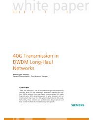
Figure 1: Flow diagram of testing lifetime.<br />
<strong>Test</strong> Network Configuration<br />
BTexact available/supplied<br />
Infrastructure to supplier<br />
Supplier offer stating equipment and<br />
requirements.<br />
No<br />
Agreement<br />
<strong>Test</strong> <strong>Plan</strong> <strong>for</strong> <strong>Optical</strong> <strong>Grooming</strong> <strong>Switches</strong><br />
The basic configuration consists of 4 nodes named New York, London, Los Angeles, Paris.<br />
Within an operators network it has been traditional to use a single protection scheme over a<br />
plat<strong>for</strong>m, or network tier. It may be advantageous to an operator to use switches to provide<br />
interconnection between networks running different protection schemes. The ability to<br />
support multiple protection schemes on the same switch node may have advantages.<br />
Yes<br />
Equipment documentation provided by<br />
supplier in advance of equipment<br />
Supplier equipment installation and<br />
commissioning.<br />
Supplier test and handover to BTexact<br />
BTexact fixed 10-day testing<br />
period.<br />
Does not include BTexact or<br />
Supplier de-commissioning<br />
and equipment removal<br />
8
<strong>Test</strong> <strong>Plan</strong> <strong>for</strong> <strong>Optical</strong> <strong>Grooming</strong> <strong>Switches</strong><br />
It is required to test a two basic resilience options:- mesh restoration and BLSR/MS-SPRING<br />
rings. To ease understanding of test results, it is proposed to configure the test network into<br />
two basic configurations:-<br />
Configuration A. This will be used to test mesh restoration and linear MSP.<br />
Configuration B. This will be used to test BLSR/MS-SPRINGs<br />
The process used will be as follows:-<br />
Step 1. Vendor installs and commissions configuration A.<br />
Step 2. BTexact per<strong>for</strong>m test cased on configuration A.<br />
Step 3. Vendor installs and commissions configuration B.<br />
Step 4. BTexact per<strong>for</strong>m test cases on configuration B.<br />
Step 5. Review results.<br />
Note the same hardware will be used <strong>for</strong> configurations A and B.<br />
Within this document the following terms apply:-<br />
Trunks : - line side connections between switches.<br />
Tribs:- client side connections between a switch and a client.<br />
Trails: - circuits set up across the network.<br />
The supplier will install and commission trunks and tribs at commissioning, including the<br />
required resilience options. During testing BTexact will then set up trails over the provided<br />
tribs and trunks.<br />
A mixture of attenuators and fibre reels will be used to interconnect the switches. BTexact<br />
can provide either SC or FC/PC connector patch leads to interconnect the switch and connect<br />
BTexact’s test equipment and fibre spans. If any other type of interface is used on the<br />
supplier’s switches, conversion patch leads to convert to FC/PC (with a minimum length of<br />
2m) should be provided. If attenuators are required when looping back a short-reach interface,<br />
the supplier should provide these.<br />
All installation and commissioning at Adastral Park will be per<strong>for</strong>med by the vendor with<br />
minimal involvement from BTexact. The vendor will be provided with a lab. Two vendors<br />
involved with the <strong>Light</strong> <strong>Reading</strong> evaluation will not be expected to share a lab. Typically<br />
BTexact will evaluate vendor A’s product while in parallel vendor B installs and commissions<br />
in a separate lab. On successful completion of installation the vendor will provide BTexact<br />
with a clear, written statement that installation and commissioning is completed successfully<br />
and that testing can proceed. While BTexact will have minimal involvement in installation<br />
and commissioning by the vendor, we will record the duration the I&C process and also our<br />
perception of the ease, rigour and professionalism with which the vendor per<strong>for</strong>ms.<br />
The supplier will provide a network management system as would be used to manage a large,<br />
operational network – a craft terminal or element manager alone will not suffice. Easy to use<br />
point-and-click provisioning is a key requirement <strong>for</strong> carriers and so BTexact will expect to<br />
make extensive use of it throughout the evaluation period. If during a particular test case,<br />
provisioning a particular circuit proves so difficult that it cannot easily be per<strong>for</strong>med by<br />
BTexact within a reasonable time period then this will be used as evidence that point-andclick<br />
provisioning is not user friendly.<br />
The vendor will provide any network management servers and terminals required.<br />
9
<strong>Test</strong> <strong>Plan</strong> <strong>for</strong> <strong>Optical</strong> <strong>Grooming</strong> <strong>Switches</strong><br />
A standard DCN configuration will be provided by BTexact to ensure that all vendors are<br />
being compared fairly. IP addresses will be allocated <strong>for</strong> equipment at each node to simulate a<br />
main and backup DCN network. IP addresses will be allocated <strong>for</strong> the management system.<br />
In-band management should also be provided so that if both primary and secondary out-ofband<br />
DCN connections fail then management is still possible via in-band communications.<br />
Synchronisation references will be provided by BTexact – either 1.5Mbit/s or 2Mbit/s as<br />
preferred by the vendor.<br />
Server<br />
Workstation<br />
Management Network<br />
Figure 6: DCN network architecture.<br />
Switch Switch<br />
Configuration A<br />
The configuration of trunks is as shown the figure below.<br />
<strong>Optical</strong> switch<br />
Node Network<br />
Switch<br />
10
4 OC-48s<br />
over a WDM<br />
<strong>Test</strong> <strong>Plan</strong> <strong>for</strong> <strong>Optical</strong> <strong>Grooming</strong> <strong>Switches</strong><br />
PAR #2 LON<br />
#1 #2 #3 #4 #5<br />
WDM<br />
#1 #2 #3 #4<br />
#6<br />
Figure 2: Configuration A.<br />
#7<br />
#6<br />
#5<br />
2 OC-48s 1+1 MSP<br />
OC-48<br />
LA #1 NY<br />
#7<br />
Configuration A<br />
OC-192s BLSR<br />
OC-192<br />
#1<br />
#3<br />
#3<br />
#2<br />
#4<br />
#4<br />
OC-192<br />
Note the supplier need not provide the WDM system shown in the diagram. Each of the 4<br />
OC-48s shown being carried over the WDM will in fact be transported over a separate fibre<br />
pair. However the 4 OC-48s should otherwise be treated as if they are being carried on a<br />
WDM system or over separate fibre pairs in the same cable.<br />
If one of the wavelengths between Paris and LA fails the system should first try and switch<br />
the traffic over to a spare wavelength on the WDM system. If no spare wavelengths are<br />
available (e.g. if the entire WDM system/cable is broken) then the traffic should be re-routed<br />
via a different route.<br />
For this configuration, the “cost” or “weighting” of each hop should be set to be equal.<br />
The tables below give the interfaces required in each node <strong>for</strong> Configuration A. If a trunk<br />
interface variant is not supported this fact should be highlighted to BTexact and it should be<br />
replaced with another interface in order to maintain connectivity. However this will mean<br />
that some test cases cannot be per<strong>for</strong>med and this fact will be recorded. Note interfaces<br />
required <strong>for</strong> Configuration B are a subset of those required <strong>for</strong> Configuration A.<br />
Paris<br />
Interface name Description Interface variant<br />
PAR#1 SONET OC-48 WDM<br />
PAR#2 OC-48 LH<br />
PAR#3 OC-48 SH<br />
PAR#4 OC-48 SH<br />
11
PAR#5 OC-48 SH<br />
PAR#6 OC-48 SH<br />
PAR#7 OC-48 SH<br />
Client Interface<br />
Name<br />
PAR#8 OC-48 SH<br />
PAR#9 STM-16 SH<br />
PAR#10 OC-48 SH<br />
PAR#13 OC-192 SH<br />
PAR#16 OC-12 SH<br />
PAR#17 GigE<br />
LON#18 100MBaseT<br />
Los Angeles<br />
Interface name Description Interface variant<br />
LA#1 SONET OC-48 WDM<br />
LA#2 OC-48 LH<br />
LA#3 OC-48 SH<br />
LA#4 OC-48 SH<br />
LA#5 OC-192 SH<br />
LA#6 OC-192 SH<br />
LA#7 OC-192 VSR<br />
Client Interface<br />
Name<br />
LA#8 OC-48 SH<br />
LA#9 OC-48 SH<br />
LA#10 STM-64 VSR<br />
LA#11 OC-192 WDM<br />
New York<br />
Interface name Description Interface variant<br />
NY#’1 OC-192 VSR<br />
NY#2 OC-192 SH<br />
NY#3 OC-48 SH<br />
NY#4 OC-192 OTN enabled if<br />
possible<br />
(i.e G709 wrapper)<br />
Client Interface<br />
Name<br />
NY#6 OC-48 SH<br />
NY#7 STM-16 SH<br />
NY#12 OC-3 SH<br />
NY#14 100M BaseT<br />
NY#15 GigE<br />
London<br />
Interface name Description Interface variant<br />
LON#1 OC-48 SH<br />
LON#2 OC-48 SH<br />
LON#3 OC-192 SH<br />
LON#4 OC-192 OTN enabled if<br />
possible (i.e.G709<br />
wrapper)<br />
<strong>Test</strong> <strong>Plan</strong> <strong>for</strong> <strong>Optical</strong> <strong>Grooming</strong> <strong>Switches</strong><br />
12
Client Interface<br />
Name<br />
LON#5 STM-16 SH<br />
LON#6 OC-48 SH<br />
LON#11 STM-64 VSR<br />
Table 1: list of interfaces required <strong>for</strong> trunk interconnects.<br />
N.B. SH=Short haul, LH=Long haul, WDM=wavelength division multiplexed<br />
specified tuned laser, OTN=<strong>Optical</strong> Transport Network (developing<br />
standards such as ITU-T G.709), VSR=Very Short Reach 10-Gbit/s serial<br />
transponder interfaces.<br />
Configuration B<br />
<strong>Test</strong> <strong>Plan</strong> <strong>for</strong> <strong>Optical</strong> <strong>Grooming</strong> <strong>Switches</strong><br />
This configuration is used to test BLSR/MS-SPRING networks. Note in order to reduce the<br />
number of interfaces the supplier has to provide, only 2 fibre BLSR/MS-SPRINGS are tested.<br />
If the supplier does not support 2-fibre BLSR/SPRINGS but DOES support 4 fibre<br />
BLSR/SPRINGS then they may offer an equivalent network based on 4-fibre<br />
BLSR/SPRINGS – with an associated increase in the number of interfaces required.<br />
However, the lack of support <strong>for</strong> 2-fibre BLSR/SPRINGS will be recorded.<br />
#1<br />
PAR LON<br />
#1 #2<br />
#3<br />
#5<br />
#5<br />
#4<br />
OC-48<br />
2f BLSR<br />
STM-64<br />
2f MS-SPRING<br />
LA NY<br />
Figure 3: Configuration B.<br />
Configuration B<br />
Unprotected OC-48<br />
#1<br />
#3<br />
#2<br />
#3<br />
#2<br />
#4<br />
#4<br />
13
<strong>Test</strong> <strong>Plan</strong> <strong>for</strong> <strong>Optical</strong> <strong>Grooming</strong> <strong>Switches</strong><br />
Within Table 1 (Configuration A) if any of the SONET/SDH interfaces types are not<br />
available, they should be replaced with the nearest equivalent interface in order to maintain<br />
connectivity between nodes.<br />
<strong>Test</strong> Methodology<br />
A 10 day test window has been deliberately set to assess the most important functions of each<br />
switch. It is not proposed to fully test all possible permutations of interface and protection.<br />
The proposed test plan will sufficiently test a sample of the permutations in order to:<br />
• Gain confidence that the equipment per<strong>for</strong>ms as expected.<br />
• Assess the user-friendliness of the equipment and network management system.<br />
• Assess the operational procedures required.<br />
• Understand the flexibility of the switches.<br />
The test plan is broken into blocks of sub tests, each sub test having an expected result. The<br />
tests within the blocks will be per<strong>for</strong>med in order but the blocks themselves are designed so<br />
they can be per<strong>for</strong>med in a different order or even in parallel if required.<br />
Process if major failure during testing.<br />
The flow chart in figure 7 shows the process to be followed if a major problem is found<br />
during testing.<br />
14
Major problem during BTexact testing<br />
BTexact Contacts Supplier<br />
Supplier requests halt<br />
to testing<br />
Supplier fixes<br />
problem in<br />
bl i<br />
Yes<br />
Yes<br />
Continue with test plan<br />
Figure 7: Flow Diagram of BTexact procedure on major failure.<br />
No<br />
No<br />
<strong>Test</strong> <strong>Plan</strong> <strong>for</strong> <strong>Optical</strong> <strong>Grooming</strong> <strong>Switches</strong><br />
Continue<br />
testing with<br />
bl<br />
Yes<br />
State impact<br />
No<br />
Stop test plan<br />
consider<br />
rescheduling<br />
15
<strong>Test</strong> <strong>Plan</strong> <strong>for</strong> <strong>Optical</strong> <strong>Grooming</strong> <strong>Switches</strong><br />
Interfaces and interconnects.<br />
It is assumed that SONET/SDH interfaces will be used to interconnect the switches. The same<br />
interface may have different reach optics available in order to provide either:<br />
• Direct switch interconnection.<br />
• Switch interconnection via a line system.<br />
• Connection to data ingress.<br />
Within an operators network VSR 10-Gbit/s serial transponder interfaces may be used <strong>for</strong><br />
direct interface between co-located switches or interconnect to line equipment with VSR<br />
interfaces. Intrusive testing of any VSR link will not be made during these tests although<br />
functional testing over switch interconnects using VSR 10-Gbit/s serial transponder interfaces<br />
would be included.<br />
16
<strong>Test</strong> <strong>Plan</strong> <strong>for</strong> <strong>Optical</strong> <strong>Grooming</strong> <strong>Switches</strong><br />
<strong>Test</strong> cases, Configuration A: Mesh Restoration and various protection<br />
schemes.<br />
BLOCK 1. Trail creation and support <strong>for</strong> required interface and granularities<br />
<strong>Test</strong> Block description:<br />
<strong>Test</strong>ing of all client interfaces, their supported traffic granularities and trail creation.<br />
Procedure:<br />
Blocks of test to proceed in sequence from TCA01 to TCA09.<br />
<strong>Test</strong> equipment needed:<br />
2 OC-48/STM-16 SONET/SDH test sets.<br />
2 OC-192/STM-64 SONET/SDH test sets.<br />
Switch management system.<br />
TCA001: Configure unprotected STS-1 trail over OC-48 interface.<br />
Purpose:<br />
To confirm switch supports OC-48 interface.<br />
To confirm switch supports STS-1 granularity.<br />
To confirm the ability of the management system to correctly create and configure the trail<br />
required by the user.<br />
To confirm ease-of-use of point-and-click provisioning.<br />
To confirm point and click provisioning gives sensible routing.<br />
<strong>Test</strong> method:<br />
1. Start off with Configuration A, with no trails configured.<br />
2. Use SONET/SDH tester to generate bulk-filled STS-1 within an OC-48 and connect to<br />
tribs: PAR#8 and LA#8<br />
3. Use network management system to configure STS-1 trail between PAR#8 and LA#8<br />
4. Confirm, using switch management system, the creation of the required trail.<br />
5. Confirm, using SONET/SDH testers, error free operation of the created trail.<br />
Expected result:<br />
• SONET/SDH testers report error free transmission.<br />
• Switch management reports no alarms or warning.<br />
• Trail is routed by the obvious one hop route between LA and Paris<br />
• The management system should clearly display the following;<br />
Current route and status.<br />
Available resources.<br />
Other comments:<br />
None<br />
TC002: Attempt to delete trail with current traffic.<br />
Purpose:<br />
To confirm the ability to delete trails within the network.<br />
To confirm the switch management system adequately warns the user be<strong>for</strong>e allowing<br />
deletion of the trail.<br />
17
<strong>Test</strong> <strong>Plan</strong> <strong>for</strong> <strong>Optical</strong> <strong>Grooming</strong> <strong>Switches</strong><br />
<strong>Test</strong> method:<br />
1. Follow on from successful completion of TCA001.<br />
2. Use switch management system to attempt to delete trail.<br />
3. Confirm adequate warning appears on screen be<strong>for</strong>e deletion of trail is permitted.<br />
Expected result:<br />
• A warning will appear on the switch management system, to state this operation will<br />
be traffic affecting.<br />
• On completion SONET tester show traffic is lost.<br />
• On completion switch management system clearly shows trail is removed and<br />
capacity is now available.<br />
• The management system should clearly display the following;<br />
Current route and status.<br />
Available resources.<br />
Other comments:<br />
None<br />
TCA003: Configure unprotected STS-3c trail over OC-48 interface.<br />
Purpose:<br />
To confirm support <strong>for</strong> STS-3c concatenation.<br />
<strong>Test</strong> method:<br />
1. Start off with Configuration A, with no trails configured.<br />
2. Use SONET/SDH tester to generate bulk-filled STS-3c within an OC-48 and connect to<br />
tribs: PAR#8 and LA#8.<br />
3. Use network management system to configure STS-3c trail between PAR#8 and LA#8.<br />
4. Confirm, using switch management system, the creation of the required trail.<br />
5. Confirm, using SONET/SDH testers, error free operation of the created trail.<br />
Expected result:<br />
• SONET/SDH testers report error free transmission.<br />
• Switch management reports no alarms or warning.<br />
• Trail is routed by the obvious one hop route between LA and Paris.<br />
• The management system should clearly display the following;<br />
Current route and status.<br />
Available resources.<br />
Other comments:<br />
None.<br />
TCA004: Configure unprotected STS-12c trail over OC-48 interface.<br />
Purpose:<br />
To confirm support <strong>for</strong> STS-12c concatenation<br />
<strong>Test</strong> method:<br />
1. Start off with Configuration A, with no trails configured.<br />
2. Use SONET/SDH tester to generate bulk-filled STS-12c within an OC-48 and connect to<br />
tribs: PAR#8 and LA#8.<br />
3. Use network management system to configure STS-12c trail between PAR#8 and LA#8.<br />
4. Confirm, using switch management system, the creation of the required trail.<br />
5. Confirm, using SONET/SDH testers, error free operation of the created trail.<br />
18
Expected result:<br />
• SONET/SDH testers report error free transmission.<br />
• Switch management reports no alarms or warning.<br />
• Trail is routed by the obvious one hop route between LA and Paris.<br />
• The management system should clearly display the following;<br />
Current route and status.<br />
Available resources.<br />
Other comments:<br />
None<br />
TCA005: Configure unprotected STS-48c trail over OC-48 interface.<br />
Purpose:<br />
To confirm support <strong>for</strong> STS-48c concatenation.<br />
<strong>Test</strong> <strong>Plan</strong> <strong>for</strong> <strong>Optical</strong> <strong>Grooming</strong> <strong>Switches</strong><br />
<strong>Test</strong> method:<br />
1. Start off with Configuration A, with no trails configured.<br />
2. Use 2 OC-48 testers to generate bulk-filled STS-48c within an OC-48 and connect to<br />
tribs: PAR#8 and LA#8.<br />
3. Use network management system to configure STS-48c trail between PAR#8 and LA#8.<br />
4. Confirm, using switch management system, the creation of the required trail.<br />
5. Confirm, using SONET/SDH testers, error free operation of the created trail.<br />
6. On completion of the test leave trail configured with testers showing error free operation.<br />
Expected result:<br />
• SONET/SDH testers report error free transmission.<br />
• Switch management reports no alarms or warning.<br />
• Trail is routed by the obvious one hop route between LA and Paris.<br />
• The management system should clearly display the following;<br />
Current route and status.<br />
Available resources.<br />
Other comments:<br />
NB. Use OC-48 tester <strong>for</strong> this test not OC-192. The OC-192 tester will be needed <strong>for</strong> next<br />
test.<br />
TCA006: Configure VC4 trail over STM-64 trib.<br />
Purpose:<br />
To confirm SDH STM-64 tribs are supported.<br />
To confirm VC4 granularity supported.<br />
To confirm same node can support SONET and SDH interfaces at same time.<br />
<strong>Test</strong> method:<br />
1. Following successful completion of TCA005 – PAR#8-LA#8 trail should still be up and<br />
running.<br />
2. Use 2 SDH testers to generate bulk-filled VC4 within STM-64 and connect to tribs<br />
PAR#13 and LA#11<br />
3. Use switch management system to set up VC4 trail between PAR#13 and LA#11 .<br />
Expected result:<br />
• SDH testers show LA#11-PAR#13 VC4 circuit running error free.<br />
• SDH testers show LA#8-PAR#8 STS-48c circuit running error free.<br />
• Switch management system alarm free and circuit routes are via the obvious LA-PAR<br />
one hop.<br />
19
• The management system should clearly display the following;<br />
Current route and status.<br />
Available resources.<br />
<strong>Test</strong> <strong>Plan</strong> <strong>for</strong> <strong>Optical</strong> <strong>Grooming</strong> <strong>Switches</strong><br />
Other comments:<br />
If supports STM-64 as shown in this test, and OC-48 as shown in previous tests then support<br />
<strong>for</strong> STM-16 and OC-192 can be assumed.<br />
TCA007: Confirm support <strong>for</strong> VC4-64c.<br />
Purpose:<br />
To confirm support <strong>for</strong> VC4-64c.<br />
<strong>Test</strong> method:<br />
1. Start off with empty Configuration A – no trails configured.<br />
2. Set up VC4-64c circuit between LA#11 and PAR#13.<br />
Expected result:<br />
• VC4-64c circuit set up between LA and Paris and runs error free.<br />
• The management system should clearly display the following;<br />
Current route and status.<br />
Available resources.<br />
Other comments:<br />
None.<br />
TCA008: Confirm support <strong>for</strong> 10Gbit/s VSR interface.<br />
Purpose:<br />
To confirm support <strong>for</strong> 10Gbit/s VSR interface.<br />
<strong>Test</strong> method:<br />
1. Set up VC4-64c trail via 10Gbit/s VSR tribs LON#11 and LA#10.<br />
Expected result:<br />
• 10Gbit/s circuit runs error free and is routed LON#3-LA#5<br />
• The management system should clearly display the following;<br />
Current route and status.<br />
Available resources.<br />
Other comments:<br />
None.<br />
TCA009: OC-12 and OC-3 interfaces.<br />
Purpose:<br />
To confirm the switch offers OC-12 and OC-3 interfaces.<br />
<strong>Test</strong> method:<br />
1. Start off with Configuration A, with no trails configured.<br />
2. Set up STS-1 trail between OC-12 interface PAR#16 and OC-3 interface NY#12.<br />
Expected result:<br />
• SONET tester shows error free creation of STS-1 trail<br />
• Circuit routing is via PAR#5-NY#’3<br />
• The management system should clearly display the following;<br />
Current route and status.<br />
Available resources.<br />
20
Other comments:<br />
None<br />
END OF BLOCK 1<br />
BLOCK 2. Mesh restoration and various protection mechanisms.<br />
<strong>Test</strong> Block description:<br />
<strong>Test</strong>ing of mesh restoration and various protection options<br />
Procedure:<br />
Blocks of tests to proceed in sequence from TCA010 to TCA025<br />
<strong>Test</strong> <strong>Plan</strong> <strong>for</strong> <strong>Optical</strong> <strong>Grooming</strong> <strong>Switches</strong><br />
TCA10: Confirm mesh restoration of unprotected trail in event of fibre cut<br />
Purpose:<br />
To confirm mesh restoration restores a simple unprotected circuit in event of fibre cut<br />
<strong>Test</strong> method:<br />
1. Start off with Configuration A with no trails configured<br />
2. Set up unprotected STS-1 trail from PAR#8 to NY#6<br />
3. Confirm trail is routed via shortest hop which is PAR#5-NY#3<br />
4. Confirm system alarm free and that SONET tester is error free<br />
5. Set up and monitor a second unprotected VC4-4c trail from PAR#9-LON#5<br />
6. Break fibre PAR#5-NY#3<br />
7. Measure duration of loss of traffic<br />
8. Confirm new routing<br />
Expected result:<br />
• Record loss duration of loss of traffic on STS-1 PAR#’8-NY#6<br />
• Trail should now be routed via a “2 hop” route (PAR-LON-NY or PAR-LA-NY<br />
– not important which)<br />
• Within 10 seconds switch management system should show an alarm indicating<br />
the correct position of fibre break<br />
• Second PAR#9-LON#5 circuit should be unaffected<br />
• The management system should clearly display the following;<br />
Current route and status.<br />
Available resources.<br />
Other comments:<br />
None<br />
TCA011: Confirm how mesh restoration behaves when the fibre is fixed<br />
Purpose:<br />
Following on from previous test confirm what happens when fibre is fixed<br />
<strong>Test</strong> method:<br />
1. Following on from successful completion of TCA010<br />
2. Fix fibre PAR#5-NY#3<br />
Expected result:<br />
• SONET testers show no further loss of traffic<br />
21
• Switch management system alarm cleared because fibre is fixed<br />
• Trail is still routed via 2 hop route<br />
• The management system should clearly display the following;<br />
Current route and status.<br />
Available resources.<br />
Other comments:<br />
None<br />
<strong>Test</strong> <strong>Plan</strong> <strong>for</strong> <strong>Optical</strong> <strong>Grooming</strong> <strong>Switches</strong><br />
TCA012a: Confirm that the user can request automatic reoptimisation of circuit routings.<br />
Purpose:<br />
Following a restoration event circuits may be following non-optimal routes with long-term<br />
detrimental impact on availability. At a time of the operator’s choosing it would there<strong>for</strong>e be<br />
required to ask the system to automatically reoptimise circuit routings<br />
<strong>Test</strong> method:<br />
1. Following on from successful completion of TCA011<br />
2. Ask the switch management system to reoptimise circuit routings<br />
3. Record duration of loss of traffic<br />
Expected result:<br />
• STS-1 circuit should be rerouted back to original single hop route<br />
• Measure duration of traffic loss on STS-1 circuit<br />
• VC4-4c circuit should be unaffected<br />
• The management system should clearly display the following;<br />
Current route and status.<br />
Available resources.<br />
Other comments:<br />
None<br />
TCA012b: Confirm operation of 1+1 MSP<br />
Purpose:<br />
To confirm operation of (non-revertive) 1+1 MSP<br />
<strong>Test</strong> method:<br />
1. Start off with Config A with no trails configured<br />
2. Set up unprotected STS-1 trail from PAR#8-LON#5 and connect to SONET testers<br />
3. Set up unprotected STS-3c trail from PAR#10-LA#8 and connect to SONET testers<br />
4. Look on management system and ensure STS-1 is being carried over PAR#6-LON#2<br />
working route (if not do a manual switch to make sure it is)<br />
5. Pull out card PAR#6<br />
6. Measure loss of traffic on SONET testers<br />
7. Record alarms on management system<br />
Expected result:<br />
• STS-1 should see less than 50 ms loss of traffic<br />
• Switch management system should clearly show STS-1 is now being carried over<br />
PAR#7-LON#1 trunk<br />
• STS-3c should see no loss of traffic<br />
• Within 10 seconds alarm appears on network management system to show card<br />
failure of PAR#6<br />
• The management system should clearly display the following;<br />
22
Other comments:<br />
None<br />
Current route and status.<br />
Main route and Status.<br />
Protection Route and Status.<br />
Available resources.<br />
TCA013: Confirm 1+1 MSP does not revert<br />
Purpose:<br />
To confirm 1+1 MSP is not revertive<br />
<strong>Test</strong> method:<br />
1. Following on from successful completion of TCA012<br />
2. Replace card PAR#6<br />
3. Note results on SDH testers and switch management system<br />
<strong>Test</strong> <strong>Plan</strong> <strong>for</strong> <strong>Optical</strong> <strong>Grooming</strong> <strong>Switches</strong><br />
Expected result:<br />
Card out alarm should be cleared<br />
SDH testers should show no further loss of traffic<br />
Switch management system should still show STS-1 circuit routed via PAR#7-<br />
LON#1 trunk<br />
Other comments:<br />
None<br />
TCA014: Confirm manual switch of 1+1 MSP<br />
Purpose:<br />
To confirm 1+1 MSP can be manually switched correctly<br />
<strong>Test</strong> method:<br />
1. Following on from successful completion of TCA013<br />
2. Manually switch STS-1 circuit from PAR#7-LON#1 trunk to PAR#6-LON#2 trunk<br />
Expected result:<br />
STS-1 circuit should see sub-50 ms loss of traffic<br />
Switch management system should show alarm indicating manual switch<br />
Switch management system should show STS-1 circuit now routed PAR#6-<br />
LON#2<br />
Other comments:<br />
None<br />
TCA015: Confirm loss of protection route on 1+1 MSP is handled correctly<br />
Purpose:<br />
To confirm loss of protection route on 1+1 MSP is handled correctly<br />
<strong>Test</strong> method:<br />
1. Following on from successful completion of TCA014<br />
2. Break fibre PAR#7-LON#1<br />
Expected result:<br />
No loss of traffic on SDH testers<br />
Switch management system shows circuit routings unchanged<br />
23
Switch management system shows loss of protection warning<br />
Other comments:<br />
None<br />
<strong>Test</strong> <strong>Plan</strong> <strong>for</strong> <strong>Optical</strong> <strong>Grooming</strong> <strong>Switches</strong><br />
TCA016: Confirm mesh restoration is used when working and protection 1+1 MSP<br />
trunks are failed<br />
Purpose:<br />
Confirm mesh restoration is used when working and protection 1+1 MSP trunks are failed<br />
<strong>Test</strong> method:<br />
1. Following on from successful completion of TCA015<br />
2. Pull out card PAR#6<br />
Expected result:<br />
Mesh restoration takes place and routes STS-1 via 2 hop route Par#8-PAR#5-<br />
NY#3-NY#4-LON#4-LON#5<br />
Record duration of loss of traffic on STS-1 circuit<br />
STS-3c circuit should see no loss of traffic<br />
Other comments:<br />
None<br />
TCA017: Confirm support <strong>for</strong> BLSR and mesh restoration on same switch – part A<br />
Purpose:<br />
To confirm same switch can support BLSR and mesh restoration at same time<br />
<strong>Test</strong> method:<br />
1. Start off with “clean” configuration A – no alarms and no circuits configured<br />
2. Set up unprotected STS-1 circuit from LA#8 to NY#6<br />
3. Set up unprotected STS-3c circuit from NY#7 to LON#5<br />
4. Confirm STS-1 circuit is routed via BLSR<br />
5. Identify which LA-NY fibre is the working fibre <strong>for</strong> STS-1 and break the working fibre<br />
Expected result:<br />
BLSR should switch<br />
STS-1 circuit should see sub-50ms traffic loss<br />
STS-3c circuit should see no loss of traffic<br />
Other comments:<br />
None<br />
TCA018: Confirm support <strong>for</strong> BLSR and mesh restoration on same switch – part B<br />
Purpose:<br />
To confirm same switch can support BLSR and mesh restoration at same time<br />
<strong>Test</strong> method:<br />
1. Following on from completion of TCA017<br />
2. Break fibre LON#4-NY#4<br />
Expected result:<br />
STS-1 circuit should be unaffected – no loss of traffic<br />
Switch management system should show LON#4-NY#4 fibre cut<br />
24
<strong>Test</strong> <strong>Plan</strong> <strong>for</strong> <strong>Optical</strong> <strong>Grooming</strong> <strong>Switches</strong><br />
STS-3c circuit should be mesh restored via 2 hops route – confirm on<br />
management system<br />
Record duration of loss of traffic on STS-3c circuit<br />
Other comments:<br />
None<br />
TCA019: Break both working and protection fibres in BLSR<br />
Purpose:<br />
To confirm that when both working and protection arms on BLSR are failed then mesh<br />
restoration takes place<br />
<strong>Test</strong> method:<br />
1. Following on from successful completion of TCA017 and TCA018 one fibre in the BLSR<br />
has already been broken. Now break the other one<br />
Expected result:<br />
Mesh restoration should take place on STS-1 circuit<br />
Record duration of loss of traffic on STS-1 circuit<br />
Switch management system should now show STS-1 circuit routed via NY#3-<br />
PAR#5-LA<br />
STS-3c circuit should be unaffected<br />
Other comments:<br />
None<br />
TCA20: Creation of protected trail.<br />
Purpose:<br />
To confirm the ability to create an SNCP protected circuit across the network.<br />
<strong>Test</strong> method:<br />
1. Start off with Configuration A, with no trails configured.<br />
2. Using the switch management system, create an SNCP protected STS-1 trail from PAR#8<br />
to NY#6<br />
3. Confirm the trail is working error free<br />
4. Set up an unprotected STS-3c trail from PAR#9-NY#7<br />
Expected result:<br />
• SDH testers report error free transmission.<br />
• Switch management reports no alarms or warning.<br />
• Switch management system clearly shows routing of the protected circuit – working<br />
via PAR#5-NY#3 and protection via 2 hop route (not important which)<br />
• Check the following are clearly and accurately displayed within the network view of<br />
the Management system:<br />
Current route and status.<br />
Protection route.<br />
Available resources.<br />
Any other comments:<br />
Is a screen refresh required to obtain a current view of the network?<br />
Is there an auto refresh or cycle time to refresh all ports on nodes?<br />
TCA021: Operate SNC protection (non revertive) in event of fibre cut<br />
25
<strong>Test</strong> <strong>Plan</strong> <strong>for</strong> <strong>Optical</strong> <strong>Grooming</strong> <strong>Switches</strong><br />
Purpose:<br />
To confirm the correct operation of the protection mechanism of the SNCP protected trail.<br />
<strong>Test</strong> method:<br />
1. Following on from successful completion of TCA020<br />
2. Break fibre PAR#5-NY#’3<br />
Expected result:<br />
• STS-1 circuit switched over protection trail within 50ms.<br />
• Switch management system shows location of fibre break and that switch has<br />
occurred.<br />
• STS-3c circuit unaffected<br />
.<br />
Any other comments:<br />
None<br />
TCA022: Fix broken fibre on 1+1 SNCP<br />
Purpose:<br />
Confirm 1+1 SNCP protection is non-revertive<br />
<strong>Test</strong> method:<br />
1. Following on from successful completion of TCA021<br />
2. Fix fibre PAR#5-NY#3<br />
Expected result:<br />
• Alarms removed on main route.<br />
• Traffic still carried over protection route.<br />
• No loss of traffic on either STS-1 or STS-3c circuit<br />
• Available resources should show the main route is not available <strong>for</strong> extra traffic,<br />
which would prevent restoration of currently protected traffic.<br />
Any other comments:<br />
None<br />
TCA23: Force restoration of 1+1 SNCP<br />
Purpose:<br />
Confirm the ability of the switch management system to <strong>for</strong>ce a restoration back to the<br />
original working trunk<br />
<strong>Test</strong> method:<br />
1. Following on from successful completion of TCA022<br />
2. Using switch system management, <strong>for</strong>ce restoration back on to main route and measure<br />
time to restoration.<br />
Expected result:<br />
• A warning will appear on the management system, to state that this operation will be<br />
traffic affecting.<br />
• STS-1 circuit returned to its original route – via trunk PAR#5-NY#3<br />
• STS-1 circuit sees 50 ms traffic hit<br />
• STS-3c circuit unaffected<br />
• Management system clearly and accurately displays:<br />
Current route.<br />
Status and alarms <strong>for</strong> main route.<br />
26
Protection route.<br />
Available resources.<br />
Any other comments:<br />
None<br />
TCA024: Fail protection arm of 1+1 SNCP<br />
Purpose:<br />
Confirm correct operation of 1+1 SNCP circuit in event of loss of protection<br />
<strong>Test</strong> <strong>Plan</strong> <strong>for</strong> <strong>Optical</strong> <strong>Grooming</strong> <strong>Switches</strong><br />
<strong>Test</strong> method:<br />
1. Following on from successful completion of TCA023<br />
2. Use switch management system to identify protection route <strong>for</strong> the 1+1 protected SNCP<br />
circuit – and break a fibre on that protection route<br />
Expected result:<br />
• No loss of traffic on either STS-1 or STS-3c circuit<br />
• Alarm raised to indicate and locate loss of protection<br />
• Mesh restoration takes place to set up a “new” protection route – so we again end up<br />
with 1+1 protected circuit<br />
Any other comments:<br />
None<br />
TCA25: <strong>Test</strong> operation of SNCP circuit in dual fault scenario<br />
Purpose:<br />
Confirm that when both working and protection arms of 1+1 SNC circuit are broken then<br />
mesh restoration takes place<br />
<strong>Test</strong> method:<br />
1. Following on from successful completion of TCA023<br />
2. Break fibre PAR#5-NY#3 (working path <strong>for</strong> STS-1 circuit)<br />
Expected result:<br />
• Protection switching should now take place onto the “new” protection arm<br />
• STS-1 circuit sees sub-50ms traffic loss<br />
• New routing is obvious from switch management system<br />
Any other comments:<br />
None<br />
BLOCK 3. Trail reservation and Inverse Multiplexing.<br />
END OF BLOCK 2<br />
<strong>Test</strong> Block description:<br />
Creation of a OC-192 trail over four x OC-48 trunks. Reserving network resources<br />
<strong>for</strong> later use.<br />
Procedure:<br />
Blocks of tests to proceed in sequence from TCA26 to TCA31<br />
27
<strong>Test</strong> <strong>Plan</strong> <strong>for</strong> <strong>Optical</strong> <strong>Grooming</strong> <strong>Switches</strong><br />
TCA026: Reserve STS-192c trail across network without applying any data traffic to<br />
client interfaces.<br />
Purpose:<br />
To confirm the ability of the switch management system to reserve resources across the<br />
network without applying data traffic to the reserved trail.<br />
To confirm support <strong>for</strong> inverse multiplexing of OC-192 over 4 OC-48s<br />
<strong>Test</strong> method:<br />
1. Start off with Configuration A, with no trails configured.<br />
2. Use switch management system to request an unprotected STS-192c trail from LA#11 to<br />
PAR#13 – but do not connect up to SDH testers<br />
Expected result:<br />
• Confirm trail successfully reserved.<br />
• For the given network configuration the capacity should be reserved via the 4 OC-48s<br />
between Paris and LA<br />
• Switch management reports no alarms or warning.<br />
• Check the following are clearly and accurately displayed within the network view of<br />
the Management system:<br />
Current route and status.<br />
Available resources.<br />
Any other comments:<br />
If inverse multiplexing is not supported then this will be noted. The following<br />
reservation tests will then be per<strong>for</strong>med using an OC-48 circuit and suitable<br />
adjustments to the tests to be defined by BTexact.<br />
TCA27: Attempt to remove resources required by the previously reserved trail.<br />
Purpose:<br />
To confirm the switch management system shall warn to the user the resources about to be<br />
removed are reserved <strong>for</strong> an assigned/reserved trail.<br />
To confirm the switch management system shall not remove reserved network resources<br />
without high priority over-ride from operator<br />
<strong>Test</strong> method:<br />
1. Following on from successful completion of TCA26.<br />
2. Using the switch management system, attempt to remove the resources allocated to the<br />
reserved trail.<br />
3. Confirm alarms associated with the removal of network resources.<br />
Expected result:<br />
• A warning will appear on the management system.<br />
• Check the following are clearly and accurately displayed within the network view of<br />
the Management system:<br />
Current route and status.<br />
Available resources.<br />
Any other comments:<br />
None<br />
TCA028: Attempt to create a trail using any of the resources required by the previously<br />
reserved trail – part A.<br />
Purpose:<br />
28
<strong>Test</strong> <strong>Plan</strong> <strong>for</strong> <strong>Optical</strong> <strong>Grooming</strong> <strong>Switches</strong><br />
To confirm that if resources are already reserved the system will not allow them to be used <strong>for</strong><br />
a new circuit – even if this means new circuit cannot be created.<br />
<strong>Test</strong> method:<br />
1. Following on from successful completion of TCA027<br />
2. Break fibres PAR#5-NY#3, PAR#6-LON#2, PAR#7-LON#1<br />
3. Using switch management system, attempt to create an STS-48c trail from PAR#8-LA#8<br />
4. Confirm the previously reserved resources are not re-utilised.<br />
Expected result:<br />
• A warning will appear on the management system indicating inability to use<br />
requested resources<br />
Any other comments:<br />
None<br />
TCA029: Attempt to create a trail using any of the resources required by the previously<br />
reserved trail – part B.<br />
Purpose:<br />
To confirm that when capacity has been reserved, new circuits are rerouted around it<br />
<strong>Test</strong> method:<br />
1. Following on from successful completion of TCA028<br />
2. Repair fibres PAR#5-NY#3, PAR#6-LON#2, PAR#7-LON#1<br />
3. Using switch management system, attempt to create an STS-48c trail from PAR#8-LA#8<br />
Expected result:<br />
Since all 4 OC48s on one hop route between Paris and LA are reserved, the<br />
circuit should be set up via 2 hop route PAR-NY-LA<br />
Any other comments:<br />
None<br />
TCA030: Apply data over previously reserved trail.<br />
Purpose:<br />
To confirm the switch management system has reserved the resources required <strong>for</strong> the<br />
previously reserved trail.<br />
<strong>Test</strong> method:<br />
1. Following on from successful completion of TCA029<br />
2. In TCA026 an STS-192c trail was reserved, now connect the SONET testers to generate<br />
the traffic.<br />
Expected result:<br />
• SDH testers report error free transmission.<br />
• Switch management reports no alarms or warning.<br />
Switch management system should clearly showSTS-192c circuit set up over the 4 OC48s<br />
between Paris and LA<br />
Any other comments:<br />
None<br />
TCA031: Deleted <strong>for</strong> Issue 2<br />
29
BLOCK 4. Management Bytes Path monitoring<br />
END OF BLOCK 3<br />
<strong>Test</strong> <strong>Plan</strong> <strong>for</strong> <strong>Optical</strong> <strong>Grooming</strong> <strong>Switches</strong><br />
<strong>Test</strong> Block description:<br />
Investigation of Path monitoring capabilities of the switch management system<br />
Procedure:<br />
Blocks of tests to proceed in sequence from TCA32 to TCA034<br />
<strong>Test</strong> equipment needed:<br />
Four SONET/SDH test sets.<br />
OTN <strong>Test</strong>er<br />
<strong>Optical</strong> coupler.<br />
<strong>Optical</strong> power meter.<br />
Variable attenuator.<br />
Switch management system.<br />
Craft terminal.<br />
<strong>Test</strong> equipment placement and set-up:<br />
A SONET/SDH protocol tester to monitor traffic at Port A.<br />
• Clock from received optical<br />
• Data <strong>Optical</strong> OC192 STS-192c bulk<br />
A SONET/SDH protocol tester to monitor traffic at Port B.<br />
• Clock from received optical.<br />
• <strong>Optical</strong> OC192 STS-192c bulk<br />
A SONET/SDH protocol tester in through-mode within main trunk in direction between Port<br />
A and Port B.<br />
• Clock from received data.<br />
• Through mode.<br />
• Out of service, transparent.<br />
A SONET/SDH protocol tester in through-mode within protection trunk in direction between<br />
Port A and Port B.<br />
• Clock from received data.<br />
• Through mode.<br />
• Out of service, transparent.<br />
TCA032: SONET/SDH (B2, J0) monitoring.<br />
Purpose:<br />
To confirm the non-obtrusive monitoring of B2 and J0<br />
<strong>Test</strong> method:<br />
1. Start with Config A – no trails configured<br />
2. Insert SONET tester in “through” on trunk mode between PAR#7 and LON#1<br />
3. Use another pair of SONET testers to set up an STS-1 circuit between PAR#8 and LON#6. Set J1 to read<br />
“STS-1 circuit number 1”<br />
4. On switch management system, <strong>for</strong> PAR#7 and LON#7, set J0 to read “Paris#7-LON#1 OC-48 trunk”<br />
5. Use the in-line Agilent SONET tester to read J0 and J1 and confirm they give expected<br />
values<br />
6. Using the in-line Agilent SONET/SDH <strong>Test</strong>ers, insert known B2 error rate on the<br />
working trail.<br />
30
<strong>Test</strong> <strong>Plan</strong> <strong>for</strong> <strong>Optical</strong> <strong>Grooming</strong> <strong>Switches</strong><br />
7. Confirm switch management system reads correct value of B2<br />
8. Use switch management system to set a B3 threshold at which “STS-1 circuit number 1<br />
should switch”.<br />
9. Use Agilent SDH/SONET tester in through mode to set the value of B3 to just better than<br />
the B3 switching threshold set in 8. Confirm STS-1 circuit does not switch.<br />
10. Use Agilent SDH/SONET tester in through mode to set the value of B3 to just worse than<br />
the B3 switching threshold set in 8. Confirm STS-1 circuit does switch.<br />
Expected result:<br />
Throughout trail, the ability to per<strong>for</strong>m non-intrusive monitoring of B2 and J0 bytes<br />
at all trail interfaces.<br />
Any other comments:<br />
None<br />
TCA33: <strong>Optical</strong> Power Monitoring.<br />
Purpose:<br />
To confirm the switch management system displays alarms on low optical power to<br />
interfaces.<br />
<strong>Test</strong> method:<br />
1. Start with config A – no trails configured<br />
2. Insert variable attenuator in LON#4-NY#4 trunk<br />
3. Confirm all alarms are cleared and the error free operation of the trail<br />
4. Increase optical attention on the attenuator<br />
5. Confirm the switch management system displays alarms indicating optical power is<br />
reduced – BEFORE traffic is effected.<br />
Expected result:<br />
Warning alarms displayed to the user, indicating low optical power on a network<br />
trunk.<br />
Any other comments:<br />
None<br />
TCA034: Confirm support <strong>for</strong> option of G709 digital wrappers on trunks<br />
Purpose:<br />
To confirm the switch offers option of support <strong>for</strong> G709 digital wrappers on trunks<br />
<strong>Test</strong> method:<br />
1. Start with config A with no trails configured.<br />
2. Insert OTN <strong>Test</strong>er in trunk LON#4-NY#4<br />
3. Set up transparent OC-48 trail from NY#6-LON#6<br />
4. Use in-line OTN tester to modify path trace bytes in digital wrapper and confirm switch<br />
management system sees correctly<br />
5. Use in-line OTN tester to add some errors and confirm error pre and post FEC error rates<br />
are correctly reported by switch management system<br />
Expected result:<br />
• Management system clearly and accurately displays:<br />
Notification of Pre-FEC error rate.<br />
Status and alarms <strong>for</strong> OTN route.<br />
Available resources.<br />
Any other comments:<br />
31
None<br />
END OF BLOCK 4<br />
BLOCK 5. Ethernet Service provisioning using 10/100 BaseT or GigE.<br />
<strong>Test</strong> Block description:<br />
Investigate provisioning of Ethernet services<br />
Procedure:<br />
Block of test to be proceeded in sequence from TCA035 to TCA037<br />
<strong>Test</strong> equipment needed:<br />
Ethernet tester<br />
Computer running BTexact <strong>Test</strong> software interfacing to testers.<br />
<strong>Test</strong> equipment placement and set-up:<br />
Ethernet <strong>Test</strong>er connect to ‘A’ client side interface<br />
• Data rate according to interface and SLA <strong>for</strong> service<br />
Ethernet <strong>Test</strong>er connect to ‘B’ client side interface<br />
• Data rate according to interface and SLA <strong>for</strong> service<br />
<strong>Test</strong> <strong>Plan</strong> <strong>for</strong> <strong>Optical</strong> <strong>Grooming</strong> <strong>Switches</strong><br />
TCA035: Confirm support <strong>for</strong> gigabit ethernet interface and granularity<br />
Purpose:<br />
To confirm gigabit ethernet interface is supported<br />
To confirm switch can cope with gigabit ethernet granularity<br />
<strong>Test</strong> method:<br />
1. Start off with Configuration A, with no trails configured.<br />
2. Break fibre PAR#5-NY#3<br />
3. Use ethernet tester and switch management system to set up gigabit ethernet trail between<br />
tribs PAR#17 and NY#15<br />
4. Confirm, using switch management system, the creation of the required trail.<br />
5. Confirm, using ethernet tester, error free operation of the created trail.<br />
6. Repair fibre PAR#5-NY#3<br />
Expected result:<br />
• ethernet tester report no packet loss.<br />
• Switch management reports no alarms or warning.<br />
• Circuit is routed via 2 hop route PAR-LON-NY or PAR-LA-NY<br />
Other comments:<br />
Purpose of breaking fibre PAR#5-NY#3 <strong>for</strong> this test was to ensure switch can route gigabit<br />
ethernet granularity<br />
TCA36: Exercise gigabit ethernet interface<br />
Purpose:<br />
To confirm the ability of switch management system to provision and provide Ethernet<br />
Services<br />
<strong>Test</strong> method:<br />
1. Following on from successful completion of TCA035<br />
2. Increase output from ethernet <strong>Test</strong>er.<br />
32
<strong>Test</strong> <strong>Plan</strong> <strong>for</strong> <strong>Optical</strong> <strong>Grooming</strong> <strong>Switches</strong><br />
3. Using management interface of ethernet tester, confirm packet losses above agreed SLA<br />
or available bandwidth.<br />
Expected result:<br />
ethernet tester reports packet loss <strong>for</strong> higher throughput agreed under SLA agreement or<br />
available bandwidth on interface.<br />
Switch management system gives sensible outputs<br />
Any other comments:<br />
Confirm any alarms displayed on the switch management system<br />
Repeat tests as required to test other rate Ethernet interfaces.<br />
TCA037: Confirm support <strong>for</strong> 10/100Base T ethernet interfaces and that switch can<br />
transport 100Mbit/s ethernet services<br />
Purpose:<br />
To confirm 10/100 BaseT ethernet interface is supported<br />
To confirm switch can cope with 100Mb/s ethernet granularity<br />
<strong>Test</strong> method:<br />
1. Start off with Configuration A, with no trails configured.<br />
2. Break fibre PAR#5-NY#3<br />
3. Use ethernet tester and switch management system to set up 100Mb/s ethernet trail between tribs PAR#18<br />
and NY#14<br />
4. Confirm, using switch management system, the creation of the required trail.<br />
5. Confirm, using ethernet tester, error free operation of the created trail.<br />
6. Repair fibre PAR#5-NY#3<br />
Expected result:<br />
• ethernet tester report no packet loss.<br />
• Switch management reports no alarms or warning.<br />
• Circuit is routed via 2 hop route PAR-LON-NY or PAR-LA-NY<br />
Other comments:<br />
Purpose of breaking fibre PAR#5-NY#3 <strong>for</strong> this test was to ensure switch can route ethernet<br />
granularity<br />
END OF BLOCK 5<br />
BLOCK 6. Multiple payloads trunk filling, grooming and Virtual Concatenation<br />
<strong>Test</strong> Block description:<br />
Investigation mixed granularity payloads and virtual concatenation.<br />
<strong>Test</strong> equipment needed:<br />
Four SONET/SDH test sets.<br />
TCA038: Carry multiple SONET payloads through single interface<br />
Purpose:<br />
To confirm can mix different payloads within one trib and trunk<br />
33
<strong>Test</strong> method:<br />
1. Start with Config A and no trails configured<br />
2. Break fibres PAR#2-LA#2, PAR#3-LA#3, PAR#4-LA#4<br />
3. Connect Agilent SONET/SDH testers to PAR#8 and LA#8<br />
4. Simultaneously set up following unprotected trails from PAR#8-LA#8<br />
♦ 3 off STS-12c<br />
♦ 3 off STS-3c<br />
♦ 2 off STS-1<br />
<strong>Test</strong> <strong>Plan</strong> <strong>for</strong> <strong>Optical</strong> <strong>Grooming</strong> <strong>Switches</strong><br />
Expected result:<br />
All trails should be error free<br />
Switch management system should show all trails being routed via PAR#1-LA#1<br />
trunk<br />
Switch management system should show one spare STS-1 on PAR#1-LA#1 trunk<br />
Any other comments:<br />
None<br />
TCA039a: Confirm virtual concatenation of STS-1s<br />
Purpose:<br />
To confirm support <strong>for</strong> virtual concatenation of STS-1<br />
<strong>Test</strong> method:<br />
1. Following successful completion of TCA038 there is now just one spare STS-1 on PAR#1-LA#1 trunk<br />
2. Repair fibre PAR#2-LA#2<br />
3. Reserve following capacity between PAR#10 and LA#9 (but do not connect testers)<br />
4. 3 off STS-12c<br />
5. 3 off STS-3c<br />
6. 1 off STS-1<br />
7. Attempt to set up STS-3c circuit from PAR#13-LA#11 – reserve it and put on the traffic<br />
Expected result:<br />
There is 1 spare STS-1 on trunk PAR#1-LA#1 and 2 spare STS-1 between<br />
PAR#10-LA#9. The system should there<strong>for</strong>e be able to set up the STS-3c using<br />
virtual concatenation<br />
PAR#13-LA#11 circuit should be error free<br />
Switch management system should make it clear what is going on<br />
Any other comments:<br />
None<br />
TCA039b: <strong>Test</strong> grooming of STS-1s<br />
Purpose:<br />
To confirm grooming of STS-1s<br />
<strong>Test</strong> method:<br />
1. Start off with Configuration A with no trails configured.<br />
2. Set up following trails from PAR#8-LA#8 :- 1 xSTS-1, 1x STS-3c, 1x STS-12c.<br />
Leave the rest of the STS-1s unequipped<br />
34
<strong>Test</strong> <strong>Plan</strong> <strong>for</strong> <strong>Optical</strong> <strong>Grooming</strong> <strong>Switches</strong><br />
3. Set up an additional STS-1 trail from PAR#9-LA#8<br />
4. Confirm that all trails are error free and that switch management system shows<br />
circuits routed between Paris and LA.<br />
Expected result:<br />
The switch should groom such that the final STS-1 takes the place of unequipped<br />
STS-1s.<br />
Any other comments:<br />
None<br />
END OF BLOCK 6<br />
BLOCK 7. SONET to SDH conversion and High Order SONET STS-1 to Lower Order SDH AU3<br />
<strong>Test</strong> Block description:<br />
Investigation of SONET to SDH conversion.<br />
Procedure:<br />
Blocks of tests to proceed in sequence from TCA40 to TCA041.<br />
<strong>Test</strong> equipment needed:<br />
Two SONET/SDH test sets.<br />
Switch management system.<br />
Computer running Exact <strong>Test</strong> software interfacing to testers.<br />
<strong>Test</strong> equipment placement and set-up:<br />
A SONET/SDH protocol tester to monitor traffic at Port A (PAR#8).<br />
A SONET/SDH protocol tester to monitor traffic at Port B (LA#8)<br />
TCA040: SONET OC-12 circuit conversion to SDH STM-4<br />
Purpose:<br />
To confirm the correct conversion of a SONET circuit to an SDH circuit<br />
<strong>Test</strong> method:<br />
1. Start off with Configuration A, with no trails configured.<br />
2. Using switch management system, configure client interface PAR#8 as SDH<br />
3. Using switch management system, configure client interface LA#8 as SONET<br />
4. Connect SDH tester to configured SDH client interface<br />
5. Connect SONET tester to configured SONET client interface<br />
6. Using switch management system, create STS-12c/VC4-4c trail from PAR#8-LA#8<br />
7. Confirm creation of trail.<br />
Expected result:<br />
• SONET and SDH testers report error free transmission.<br />
Any other comments:<br />
None<br />
TCA041: STS-1 SPE SONET circuit will be set up to be converted to a VC3 SDH<br />
circuit.<br />
Purpose:<br />
35
<strong>Test</strong> <strong>Plan</strong> <strong>for</strong> <strong>Optical</strong> <strong>Grooming</strong> <strong>Switches</strong><br />
To confirm the ability to enable a 34/45Mbit payload (E3/DS3) within a SONET (STS-1<br />
SPE) circuit, with management in<strong>for</strong>mation, to be delivered over an SDH VC3.<br />
An STS-1 SPE SONET circuit will be set up to be converted to a VC3 SDH circuit. This<br />
conversion requires the equipment to bring the Higher Order SONET STS-1 into the switch<br />
as a Lower Order VC3 in order to encapsulate this within a TU3 and transported in the Higher<br />
Order AU4 in the SDH circuit.<br />
<strong>Test</strong> method:<br />
1. Following on from successful completion of TCA040<br />
2. Set-up tester to provide on port PAR#8 STS-1 SPE, DS3, PRBS15 within OC-48.<br />
3. Set-up tester to provide on port LA#8 AU4, VC3, 45M, PRBS15 within STM-16.<br />
4. Set-up trail across ports PAR#8 to LA#8 to carry STS-1 SPE and convert to VC3.<br />
5. Insert ALL 0’s in J1 trace Identifier (transmit and receive). This is to prevent J1 mismatch errors as J1 is 15<br />
consecutive bytes + 1 byte CRC in SDH but 64 consecutive free<strong>for</strong>m bytes in SONET.<br />
Expected result:<br />
• SONET and SDH testers report error free transmission.<br />
• Once J1 is set to all 0’s on both sides of the link no trace mismatch should be raised.<br />
Any other comments:<br />
None<br />
BLOCK 8. Tandem Connection Monitoring<br />
END OF BLOCK 7<br />
<strong>Test</strong> Block description:<br />
Investigating the Tandem Connection Monitoring capabilities.<br />
Procedure:<br />
This test checks basic Tandem Connection Monitoring functionality.<br />
If the vendors equipment does not support TCM functionality then these tests can be skipped.<br />
Lack of support <strong>for</strong> TCM will be noted. However if TCM is not supported the equipment<br />
must transport the B3, N1 and N2 bytes transparently.<br />
This test will only be conducted <strong>for</strong> a single test circuit in one direction. <strong>Test</strong> is conducted at<br />
VC-4 granularity only, they will not be repeated at different traffic granularities (N1 bytes<br />
used <strong>for</strong> VC-3’s and VC-4’s N1 bytes used <strong>for</strong> VC-2, VC-11 and VC-12).<br />
These tests do not include monitoring the status of the N bytes within the TCM section,<br />
although this is possible with an additional tester working in “through” mode.<br />
Procedure:<br />
Blocks of tests to be proceed in sequence from TCA042 to TCA049<br />
<strong>Test</strong> equipment needed:<br />
Four SONET/SDH test sets.<br />
Switch management system.<br />
<strong>Test</strong> equipment placement and set-up:<br />
36
SONET/S<br />
DH tester<br />
NE<br />
TCM-<br />
No 1 A<br />
SONET/S<br />
DH tester<br />
No 3<br />
TCA042: Create VC-4 trail across STM-16<br />
Purpose:<br />
Create a VC-4 trail across STM-16 between PAR#8 and LA#8.<br />
<strong>Test</strong> method:<br />
1. Place SONET/SDH tester in poison shown in above diagram.<br />
A SONET/SDH protocol tester to monitor traffic at Port A.<br />
• Clock from received optical<br />
• Data <strong>Optical</strong> STM-16, VC-4, bulk, PRBS15.<br />
A SONET/SDH protocol tester to monitor traffic at Port B.<br />
• Clock from received optical.<br />
• Data <strong>Optical</strong> STM16, VC-4, bulk, PRBS15.<br />
<strong>Test</strong> <strong>Plan</strong> <strong>for</strong> <strong>Optical</strong> <strong>Grooming</strong> <strong>Switches</strong><br />
A SONET/SDH protocol tester in through-mode within main trunk in direction between Port<br />
A and Port B.<br />
• Clock from received data.<br />
• Data <strong>Optical</strong> STM16, VC-4,<br />
• Through mode. Out of service, transparent.<br />
2. Create a VC-4 trail across STM-16 between PAR#8 and LA#8<br />
Expected result:<br />
• SONET and SDH testers report error free transmission.<br />
TCA043: N-byte transparency test.<br />
Purpose:<br />
Confirm transparency of N1 bytes.<br />
SONET/S<br />
DH tester<br />
<strong>Test</strong> method:<br />
1. Set A and B to “Transparent”<br />
2. Insert test pattern into N1 byte of the SONET/SDH path overhead bytes at interface A<br />
(tester No. 1). The same test patterns should appear at interface B, check on tester No. 4.<br />
Expected result:<br />
• Confirm test pattern transmitted transparently to interface B.<br />
TCA044: TC-APId path trace.<br />
Purpose:<br />
Transmission of expected TC-APId path trace.<br />
<strong>Test</strong> method:<br />
1. Set A to “Transparent” and B to terminate the TCM bytes.<br />
No 2 NE<br />
SONET/S<br />
TCM- DH tester<br />
B<br />
No 4<br />
37
<strong>Test</strong> <strong>Plan</strong> <strong>for</strong> <strong>Optical</strong> <strong>Grooming</strong> <strong>Switches</strong><br />
2. At A insert legal Tandem Connection Access Point Identifier (TC-APId) as expected by<br />
B<br />
Expected result:<br />
• No alarms/errors expected.<br />
TCA045: <strong>Test</strong> unexpected Tandem Connection Access Point Identifier.<br />
Purpose:<br />
Confirm action when unexpected TC-APId path trace is received at B.<br />
<strong>Test</strong> method:<br />
1. Set A to “Transparent” and B to terminate the TCM bytes.<br />
2. At A insert different TC-APId to that expected at B.<br />
3. Check <strong>for</strong> TC-APId between A & B using testers in through mode.<br />
Expected result:<br />
• May raise alarm on management system.<br />
• Should receive path AIS (AIS-P / AU-AIS) downstream on tester at B.<br />
• B should terminate the N1 byte with “00h”and raise a remote defect indicator<br />
upstream (TC-RDI) (observed at A).<br />
TCA046: Errors with TCM section.<br />
Purpose:<br />
Confirm TCM operation – Errors with TCM section.<br />
<strong>Test</strong> method:<br />
1. Set A to “Transparent” and B to terminate the TCM bytes.<br />
2. Insert B3 errors at tester No. 1.<br />
Expected result:<br />
• Measure same number of B3s at B.<br />
• Measure RDI & OEI (outgoing error indication) at A from B.<br />
• Management system should indicate errors occurring within the TCM section.<br />
TCA047: Errors external to TCM section.<br />
Purpose:<br />
Confirm TCM operation – Errors external to TCM section.<br />
<strong>Test</strong> method:<br />
1. Set A to “Transparent” and B to terminate the TCM bytes.<br />
2. Insert IEC at tester No. 1(incoming error count) in A.<br />
Expected result:<br />
• Expect to measure same number of B3 errors at B and to record OEI back at A.<br />
• Management system should indicate errors occurring outside the TCM section.<br />
TCA048: TC-AIS external to TCM section.<br />
Purpose:<br />
Confirm TCM operation – AIS external to TCM section.<br />
<strong>Test</strong> method:<br />
1. Set A to “Transparent” and B to terminate the TCM bytes.<br />
2. Insert incoming AIS in the IEC into A using tester No. 1.<br />
38
<strong>Test</strong> <strong>Plan</strong> <strong>for</strong> <strong>Optical</strong> <strong>Grooming</strong> <strong>Switches</strong><br />
Expected result:<br />
• Expect to measure AU-AIS at B and to record ODI back at A.<br />
• Management system should indicate AIS occurring outside the TCM section.<br />
TCA049: Link test.<br />
Purpose:<br />
To check TCM source <strong>for</strong> errors<br />
<strong>Test</strong> method:<br />
• Set A and B to terminate the TCM bytes.<br />
• Terminate TCM at A and B<br />
• Insert B3 errors in A, using tester No.1.<br />
Expected result:<br />
• Expect to measure same number at B using tester No. 4.<br />
• The inserted TC-APId, number ofB3 errors and IEC of the TCM source can be<br />
verified with tester No. 2.<br />
• The B3 errors measured at tester No. 4 must agree with B3 errors transmitted by<br />
tester No. 1 and with the B3 and IEC errors measured at tester No. 2.<br />
• The N byte is terminated at B.<br />
• Management system should indicate errors occurring outside the TCM section.<br />
Any other comments:<br />
None<br />
END OF BLOCK 8<br />
BLOCK 9. Transparency of vendors system to SONET / SDH overhead bytes. TCA53 to TCA57<br />
<strong>Test</strong> Block description:<br />
Investigate Transparency of vendors system to SONET / SDH overhead bytes.<br />
Procedure:<br />
Block of test to be proceeded in sequence from TCA50 to TCA54.<br />
<strong>Test</strong> equipment needed:<br />
Four SONET/SDH test sets.<br />
Switch management system.<br />
Computer running Exact <strong>Test</strong> software interfacing to testers.<br />
<strong>Test</strong> equipment placement and set-up:<br />
A SONET/SDH protocol tester to monitor traffic at Port A.<br />
• Clock from received optical<br />
• <strong>Optical</strong> OC-48<br />
A SONET/SDH protocol tester to monitor traffic at Port B.<br />
• Clock from received optical.<br />
• <strong>Optical</strong> OC-48<br />
A SONET/SDH protocol tester to through-mode within main trunk in direction between Port<br />
A and Port B<br />
• Clock from received data.<br />
• Through mode.<br />
• Out of service, transparent.<br />
39
<strong>Test</strong> <strong>Plan</strong> <strong>for</strong> <strong>Optical</strong> <strong>Grooming</strong> <strong>Switches</strong><br />
A SONET/SDH protocol tester to through-mode within main trunk in direction between Port<br />
A and Port B<br />
• Clock from received data.<br />
• Through mode.<br />
• Out of service, transparent.<br />
TCA050: Create protected, revertive trail.<br />
Purpose:<br />
Confirm trail creation<br />
<strong>Test</strong> method:<br />
1. Start off with Configuration A, with no trails configured.<br />
2. Using switch management system, create protected, revertive trail of OC-48 granularity<br />
3. Confirm trail is created and running error free<br />
Expected result:<br />
• SDH testers report error free transmission.<br />
• Switch management reports correct trail creation.<br />
Any other comments:<br />
None<br />
TCA051: Line Span/Multiplex section overhead bytes.<br />
Purpose<br />
Confirm the transparency of the network equipment to Line Span/Multiplex section.<br />
<strong>Test</strong> method:<br />
1. Following on from successful completion of TCA050<br />
2. Using the in-line SONET/SDH <strong>Test</strong>ers, insert an Error rate.<br />
3. Using the SONET/SDH <strong>Test</strong>ers insert a LOS and monitor the K1,K2 from the next node.<br />
Expected result:<br />
• If the switch network is transparent at the Line Span/Multiplex Section level then:<br />
B2 should remain unaltered as B2's are re-calculated at the end of a multiplex<br />
section.<br />
K1, K2 should not be altered by intermediate switch nodes.<br />
Any other comments:<br />
If the system is completely transparent the Line Span/Multiplex section overhead<br />
bytes should not be altered.<br />
TCA052: Section Span/Regenerator Section overhead bytes.<br />
Purpose<br />
Confirming transparency of the network equipment to the Section Span/Regenerator section<br />
<strong>Test</strong> method:<br />
1. Following on from successful completion of TCA051<br />
2. Using the switch management system, check if J0 can be reassigned.<br />
3. Using the in-line SONET/SDH <strong>Test</strong>ers, insert an Error rate.<br />
Expected result:<br />
• If the switch network is transparent at the Section Span/Regenerator Section level<br />
then:<br />
B1 should remain unaltered.<br />
40
J0 should remain unaltered.<br />
<strong>Test</strong> <strong>Plan</strong> <strong>for</strong> <strong>Optical</strong> <strong>Grooming</strong> <strong>Switches</strong><br />
Any other comments:<br />
If truly transparent system Section Span/Regenerator Section overhead bytes not<br />
should be altered.<br />
TCA053: Automated checks on each byte in the Regenerator and Multiplex section<br />
using test script.<br />
Purpose:<br />
Automated test script to investigate the transparency of the network equipment.<br />
<strong>Test</strong> method:<br />
1. Following on from successful completion of TCA052<br />
2. Run automated test using tool developed by BTexact to check each byte in the Section<br />
Span/Regenerator Section and Line Span/Multiplex Section, except A1, A2, J0, B1, B2,<br />
K1, K2 & H1/H2/H3 pointers 1 , recording the time at which the test was started. The tool<br />
will provide a report to indicate which bytes are sent and received correctly.<br />
Expected result:<br />
For a transparent system the SONET/SDH section overhead will remain unaltered.<br />
For a semi-transparent only a small part of the section overhead shall be processed, as clearly<br />
stated by suppliers equipment documentation.<br />
Any other comments:<br />
1 Cannot use remote control script to test these bytes. A1, A2, J0, K1 & K2 can be tested manually,<br />
separately if required. B1, B2 & AU pointers are automatically generated and so cannot be inserted<br />
arbitrarily, although B1 & B2 error handling are included as separate tests.<br />
END OF BLOCK 9<br />
BLOCK 10. Alarm reporting – including “flapping” alarms<br />
<strong>Test</strong> Block description:<br />
Investigating the ability of the switch management system to accurately and quickly<br />
display network events.<br />
Procedure:<br />
Blocks of tests to proceed in sequence from TCA054 to TC0XX.<br />
<strong>Test</strong> equipment needed:<br />
Four SONET/SDH test sets.<br />
Switch management system.<br />
Optomechanical with automated control.<br />
<strong>Test</strong> equipment placement and set-up:<br />
• Using set-up <strong>for</strong>m previous test block (Transparency of vendors system).<br />
TCA054: measure approximate time interval between breaking path, and GUI reporting<br />
fault and fault cleared.<br />
Purpose<br />
To measure the response time <strong>for</strong> displaying of alarms<br />
<strong>Test</strong> method:<br />
1. Insert optomechanical switch in main working trunk.<br />
41
<strong>Test</strong> <strong>Plan</strong> <strong>for</strong> <strong>Optical</strong> <strong>Grooming</strong> <strong>Switches</strong><br />
2. Operate unprotected trail across working trunk.<br />
3. Confirm trail is operating across working trunk.<br />
4. Operate optomechanical switch to break working path, measure time period to<br />
alarm on management system.<br />
5. Operate optomechanical switch to reconnect path, measure time period to alarm<br />
cleared on management system.<br />
Expected result:<br />
• Alarm on working path appears on management system within 10 seconds.<br />
• Alarm on working path cleared on management system within 10 seconds.<br />
Any other comments:<br />
None<br />
TCA055: Introduce automated switching to simulate flapping alarm.<br />
Purpose<br />
To simulate an intermittent, persistent fault and its effect on network management system<br />
<strong>Test</strong> method:<br />
1. Following on from completion of TCA054<br />
2. Use automated switching of optomechanical switch within working path breaking<br />
optical path <strong>for</strong> approximately 0.5 second once 30 seconds. Monitor management<br />
system and note alarm status of working path.<br />
Expected result:<br />
• Alarm on working path appears on management system within 10 seconds.<br />
• Network management system us “smart” enough to indicate this as a flapping<br />
alarm and not just repetitively raise then clear alarm<br />
Any other comments:<br />
The management system should give an operator an indication that there is a<br />
persistent recurring error on the working trunk so traffic is not put on to this trunk.<br />
The method of indication is not defined but a method of ensuring the user is alerted to<br />
a recursive error should be clear.<br />
BLOCK 11.DCN failure node isolation<br />
END OF BLOCK 10<br />
<strong>Test</strong> Block description:<br />
Investigating the reaction to the DCN failure to a single Node.<br />
Procedure:<br />
Blocks of tests to proceed in sequence from TCA056 to TCA059<br />
<strong>Test</strong> equipment needed:<br />
Switch management system.<br />
TCA056: Reaction to loss of primary out of band DCN links on single node.<br />
Purpose<br />
Confirm reaction to loss of primary DCN connection to PARIS node<br />
42
<strong>Test</strong> <strong>Plan</strong> <strong>for</strong> <strong>Optical</strong> <strong>Grooming</strong> <strong>Switches</strong><br />
<strong>Test</strong> method:<br />
1. View PARIS node on network management system and confirm management system is<br />
managing node and working correctly.<br />
2. Set up and monitor a circuit from Paris - LA<br />
3. Interrupt the IP communication primary link to Paris by removing DCN RJ45 connector.<br />
4. View management system and confirm node remains a managed item and that traffic is<br />
not effected<br />
Expected result:<br />
Alarm should appear within 10 seconds showing loss of primary DCN connection.<br />
The node should remain to be a manage node on management system with no loss of<br />
functionality.<br />
No effect on traffic on Paris-LA circuit<br />
Any other comments:<br />
None<br />
TCA057: Reaction to loss of all out of band DCN links on single node.<br />
Purpose<br />
Confirm reaction to loss of all out-of-band DCN connections to the node.<br />
<strong>Test</strong> method:<br />
1. Following on from TCA056<br />
2. View Paris node on network management system and confirm management system is<br />
managing node and working correctly.<br />
3. Interrupt the IP communication backup link to Paris by removing DCN RJ45 connector.<br />
4. View management system and confirm status of node.<br />
5. Attempt to add trail, using resources within unmanaged trail.<br />
Expected result:<br />
Critical Alarm of loss of both DCN connection within 10 seconds.<br />
Management of the node should still be possible via in-band<br />
Paris-LA circuit should still be error free<br />
Any other comments:<br />
None<br />
TCA058: Reaction to reconnection of DCN on single node.<br />
Purpose<br />
Confirm reaction to re-establishment to DCN connections to the node.<br />
<strong>Test</strong> method:<br />
1. Restore the IP communication secondary link by replacing DCN RJ45 connector.<br />
2. View management system and confirm node returns as a managed item.<br />
3. Check that node resources are available <strong>for</strong> use.<br />
4. Restore the IP communication primary link by replacing DCN RJ45 connector.<br />
Expected result:<br />
Critical Alarm of loss of DCN connection removed within 10 seconds.<br />
The node is shown as a fully managed node on management system within 1 minute.<br />
No effect on traffic over node.<br />
43
Any other comments:<br />
None<br />
<strong>Test</strong> <strong>Plan</strong> <strong>for</strong> <strong>Optical</strong> <strong>Grooming</strong> <strong>Switches</strong><br />
TCA059: Reaction to loss of all out of band DCN links on single node with no in-band<br />
management<br />
Purpose<br />
To confirm how node copes with loss of all DCN<br />
<strong>Test</strong> method:<br />
Repeat TCA057 only this time with no in-band management<br />
Expected result:<br />
Critical Alarm of loss of both DCN connection within 10 seconds.<br />
The node is shown as unmanaged node on management<br />
There should be no effect on circuits passing through node<br />
Management system prevents operations with would lead to erroneous condition due<br />
to unavailable managed resources.<br />
Any other comments:<br />
None<br />
BLOCK 12. Management and removal of cards<br />
END OF BLOCK 11<br />
<strong>Test</strong> Block description:<br />
Investigate affect and notification of card removal and replacement.<br />
Procedure:<br />
Blocks of tests to proceed in sequence from TCA059 to TCA062<br />
<strong>Test</strong> equipment needed:<br />
Switch management system.<br />
Craft terminal.<br />
TCA059: Equipment auditing of cards, and software <strong>for</strong> OC-48 interface<br />
Purpose:<br />
Confirm notification of card identification.<br />
<strong>Test</strong> method:<br />
1. For OC-48 card PAR#8 check on the switch management system can be interrogated to<br />
give the following in<strong>for</strong>mation:-<br />
Card location.<br />
Whether a card is present.<br />
Serial number.<br />
Card reference.<br />
Card operational status.<br />
Software version currently running.<br />
Fallback software version.<br />
Expected result:<br />
The Management system clearly and accurately displayed the audit in<strong>for</strong>mation.<br />
44
Any other comments:<br />
None<br />
<strong>Test</strong> <strong>Plan</strong> <strong>for</strong> <strong>Optical</strong> <strong>Grooming</strong> <strong>Switches</strong><br />
TCA060: Removal of central, critical switch matrix card.<br />
Purpose:<br />
Confirm that critical centralised switch matrix cards are 1+1 protected and can be replaced<br />
without loss of traffic<br />
<strong>Test</strong> method:<br />
1. Begin with configuration A and no circuits configured<br />
2. Break fibres PAR#7-LON#1. PAR#6-LON#2 and PAR#5-NY#3<br />
3. Set up unprotected STS-1 trail from PAR#8 to NY#6<br />
4. Confirm SONET tester is error free and that trail is routed Paris-LA-NY<br />
5. Per<strong>for</strong>m supplier specified operation to remove a central switch card in LA node<br />
6. Check management system and STS-1 traffic<br />
7. Replace card and check management system.<br />
8. Per<strong>for</strong>m supplier specified operation to reactivate card.<br />
Expected result:<br />
No loss of traffic on STS-1<br />
Within 10 seconds management system shows alarm indicating card out<br />
Any other comments:<br />
In theory the architecture may be such that there are no central, critical switch card.<br />
If so, the supplier should state this and BTexact will seek paper evidence. If BTexact<br />
are satisfied then the test will be considered passed.<br />
TCA061: <strong>Test</strong> replacement of central, critical switch matrix card<br />
Purpose:<br />
To confirm operation when central, critical switch card is replaced<br />
<strong>Test</strong> method:<br />
1. Following successful completion of TCA060<br />
2. Replace switch card<br />
Expected result:<br />
The traffic on STS-1 trail should not be affected<br />
Within 10 seconds the replaced card should be visible on management system –<br />
card status, location and available resources<br />
Any other comments:<br />
None<br />
TCA062: <strong>Test</strong> removal of network element control card<br />
Purpose:<br />
Generally there are cards within a network element which are used <strong>for</strong> management and<br />
control of the switch. Check that if removed there is no loss of traffic and an alarm is raised.<br />
<strong>Test</strong> method:<br />
1. Following successful completion of TCA061<br />
2. Remove control card from LA node<br />
45
<strong>Test</strong> <strong>Plan</strong> <strong>for</strong> <strong>Optical</strong> <strong>Grooming</strong> <strong>Switches</strong><br />
Expected result:<br />
Traffic on STS-1 trail should not be affected<br />
Alarm should be raised on switch management system within 10 seconds<br />
indicating card out<br />
Any other comments:<br />
BTexact to select the most suitable card depending on equipment implementation<br />
END OF BLOCK 12<br />
BLOCK 13. Node Failure and 1:N transponder protection on WDM system<br />
<strong>Test</strong> Block description:<br />
Procedure:<br />
Blocks of tests to proceed in sequence from TCA063 to TC065.<br />
TCA063: Node failure and trail restoration<br />
Purpose:<br />
If an entire node is destroyed in a ring network, as many as possible of the circuits passing<br />
through the node should be switched/restored<br />
<strong>Test</strong> method:<br />
1. Start off with “clean” configuration A – no alarms and no trails configured<br />
2. Break fibre PAR#5-NY#3<br />
3. Set up unprotectedSTS-1 trail from PAR#8-NY#6 and monitor traffic over it using<br />
4. Pull out all fuses (one at a time) on London node (assuming 2.5G circuit is routed via<br />
London – if via LA then use LA instead) – thus killing the node<br />
5. Confirm traffic is restored<br />
Expected results:<br />
• Single fuse removal should not be traffic affecting.<br />
• 2.5G Paris-NY circuit should be re-routed. Record the new route and the duration of<br />
any loss of traffic.<br />
• Alarms should be raised to indicate loss of node<br />
Any other comments:<br />
None<br />
TCA064: <strong>Test</strong> reboot of failed node<br />
Purpose:<br />
To see what happens when London node is on again<br />
<strong>Test</strong> method:<br />
1. Follows on from successful completion of TCA063<br />
2. Replace the fuses in London node and wait until the node is up again<br />
3. Monitor and note node rack alarms<br />
4. Monitor and management system and note time period from power on to node appears as<br />
present on management system.<br />
Expected results:<br />
46
<strong>Test</strong> <strong>Plan</strong> <strong>for</strong> <strong>Optical</strong> <strong>Grooming</strong> <strong>Switches</strong><br />
• The 2.5G Paris-NY circuit should see no loss of traffic as the London node comes<br />
on again<br />
• Network should end up in a stable, alarm free condition<br />
Any other comments:<br />
None<br />
TCA065: Confirm support <strong>for</strong> 1:N protection against WDM transponder failure<br />
Purpose:<br />
When several channels are carried over a WDM system is highly desirable to find a way of<br />
providing 1:N sparing against transponder failure. An optical grooming switch could do this.<br />
In this test the trunks between Paris and LA nodes are configured as if all are carried over a<br />
WDM system. One trunk is left spare. In the event of a failure of one of the traffic carrying<br />
trunks, it is desirable <strong>for</strong> the traffic to be switched to the spare wavelength – rather than<br />
undergoing full mesh restoration<br />
<strong>Test</strong> method:<br />
1. Start off with configuration A with no trails configured<br />
2. Break fibre PAR#4-LA#4<br />
3. Configure two STS-48c trails from PAR#8-LA#8 and PAR#10-LA#9 and monitor traffic<br />
4. Confirm the trails are carried over one hop trunks from PAR to LA (It is assumed traffic<br />
is carried on trunks PAR#1=LA#1 and PAR#2-LA#2. If not traffic is carried on PAR#3-<br />
LA#3 trunk then that is ok but rest of this test will need modifying accordingly<br />
5. Break fibre PAR#1-LA#1<br />
6. Measure effect on traffic and switch management system<br />
Expected result:<br />
♦ One of the trails should see no traffic loss and the other should see
Equipment required:<br />
2 OC-48 test sets<br />
<strong>Test</strong> method:<br />
<strong>Test</strong> <strong>Plan</strong> <strong>for</strong> <strong>Optical</strong> <strong>Grooming</strong> <strong>Switches</strong><br />
1. Using configuration B, in which vendor has configured a 2 fibre OC-48 BLSR between<br />
following interfaces (PAR#5-LON#1-LON#2-LA#2-LA#1-PAR#1)<br />
2. Set up an unprotected OC-3 trail across the BLSR from PAR#8 to LON#6<br />
Expected result:<br />
• System is user-friendly enough that BTexact can set trail up in less than 10 minutes<br />
• Traffic is carried error free<br />
• Switch management system clearly shows route of circuit<br />
Any other comments:<br />
If supplier does not support 2-fibre BLSR they may instead offer 4-fibre BLSR <strong>for</strong> this test .<br />
Lack of support <strong>for</strong> 2-fibre BLSR will be recorded.<br />
TCB002: <strong>Test</strong> protection switching in 2-fibre OC-48 BLSR<br />
Purpose:<br />
To test protection switching of 2-fibre OC-48 BLSR<br />
Equipment required:<br />
4 SDH/SONET test sets<br />
<strong>Test</strong> method:<br />
1. Follows on from successful completion of TCB001<br />
2. Set up second trail on the ring - an OC-12c between PAR#10 and LA#8.<br />
3. Break fibre PAR#5-LON#1<br />
Expected result:<br />
1. Traffic loss on the Paris-London OC3 should be less than 50 ms<br />
2. Switch management system should within 10 seconds raise an alarm indicating location<br />
of fibre break<br />
3. Switch management system clearly shows circuit switched via shared protection capacity<br />
the other way around ring. A protection switch should take place within the ring. In this<br />
test case mesh restoration should not occur<br />
4. Traffic on OC-12c between PA#S2 and LA#8 should not be affected.<br />
Any other comments:<br />
None<br />
TCB003: Confirm protection switching is revertive<br />
Purpose:<br />
To confirm protection switching is revertive <strong>for</strong> a BLSR<br />
<strong>Test</strong> method:<br />
1. Follows on from successful completion of TCB002<br />
2. Repair fibre PAR#5-LON#1<br />
Expected result:<br />
48
<strong>Test</strong> <strong>Plan</strong> <strong>for</strong> <strong>Optical</strong> <strong>Grooming</strong> <strong>Switches</strong><br />
• There should be a sub-50ms loss of traffic on the Paris-London OC3<br />
• Switch management system should clearly show circuit has reverted to original route<br />
around ring.<br />
• Alarm should be cleared.<br />
• Traffic on OC-12c between PA#S2 and LA#8 should not be affected.<br />
TCB004: <strong>Test</strong> manual protection switch on BLSR in event of planned engineering works<br />
<strong>Test</strong> purpose: To confirm that in the event of planned engineering works on the BLSR the<br />
user can manually switch traffic the other way around the ring.<br />
Equipment needed:<br />
4 SDH test sets<br />
<strong>Test</strong> method:<br />
1. Follows on from successful completion of TCB003<br />
2. Confirm all testers are error free and management system is alarm free.<br />
3. Manually switch the PAR#5-LON#1 trunk the other way around the ring<br />
Expected results<br />
• There should be a sub-50ms loss of traffic on the Paris-London OC3<br />
• Traffic on OC-12c between PA#S2 and LA#8 should not be affected.<br />
• Switch management system should clearly show circuit routings.<br />
• Alarm should appear on management system indicating manual switch has occurred.<br />
TCB005: <strong>Test</strong> that lockout prevents <strong>for</strong>ced protection switch<br />
<strong>Test</strong> purpose:<br />
To test that in the event of planned engineering works, the operator can prevent others<br />
per<strong>for</strong>ming manual protection switches onto the route being engineered.<br />
Equipment needed:<br />
4 SDH test sets<br />
<strong>Test</strong> method:<br />
1. Follows on from successful completion of TCB004<br />
2. Per<strong>for</strong>m lockout on PAR#5-LON#1 trunk<br />
3. Attempt to <strong>for</strong>ce the protection switch per<strong>for</strong>med manually in TCB004 back to PAR#5-<br />
LON#1 trunk<br />
Expected result:<br />
• Management system <strong>for</strong>bids the <strong>for</strong>ced switch<br />
• No loss of traffic on any of SONET testers<br />
• Alarm raised to indicate unsuccessful attempt to <strong>for</strong>ce traffic onto locked out trunk<br />
TCB006: <strong>Test</strong> that lockout prevents automatic protection switch of BLSR – attempts<br />
switching/restoration outside ring instead<br />
<strong>Test</strong> purpose:<br />
In the event of planned engineering works an operator may wish to prevent use of the cable<br />
being worked on by using lockout. During this period of lockout there may be a second cable<br />
break elsewhere in the ring. If so then the traffic should not be switched onto the locked cable<br />
– instead the system should switch/route the traffic via a route outside the ring.<br />
49
Equipment needed:<br />
4 SONET test sets<br />
<strong>Test</strong> <strong>Plan</strong> <strong>for</strong> <strong>Optical</strong> <strong>Grooming</strong> <strong>Switches</strong><br />
<strong>Test</strong> method:<br />
1. Follows on from successful completion of TCB005<br />
2. Confirm that lockout is still in place and that circuits are correctly routed and all test sets<br />
are error free<br />
3. Break PAR#1-LA#1 fibre<br />
Expected result<br />
• Within 10 seconds alarm should be raised indicating location of fibre break<br />
• Both the OC3 and OC12c circuits will see a brief loss of traffic – the duration of<br />
which will be recorded in each case<br />
• Switch management system should clearly show that neither trail has been<br />
routed/switched onto PAR#5-LON#1 fibre. The actual routing will be recorded <strong>for</strong><br />
each trail.<br />
Other comments:<br />
Depending on supplier implementation either protection switching or mesh restoration may<br />
occur here – and it may be different <strong>for</strong> the OC3 and OC12c circuits. An obvious measure of<br />
success is that the shorter the loss of traffic the better.<br />
TCB007: Confirm that when lockout is removed the management system allows easy<br />
reoptimisation of network.<br />
<strong>Test</strong> purpose:<br />
Following successful completion of TCB006, the network is in a complex, dual-fault situation<br />
with quite tortuous circuit routings. Once all faults are repaired, it is important that the<br />
operator can easily use the management system to reoptimise circuit routings.<br />
Equipment needed:<br />
4 SONET test sets<br />
<strong>Test</strong> method:<br />
1. Follows on from successful completion of TCB006<br />
2. First confirm that the results of TCB006 are fully and accurately documented<br />
3. Repair the PAR#5-LON#1 fibre and record any traffic loss and reports/alarms on<br />
management system<br />
4. Remove the lockout on PAR#5-LON#2 fibre and record any traffic loss and<br />
reports/alarms on management system<br />
5. Use the management system to automatically reoptimise the network configuration and<br />
circuit routing<br />
6. Note durations of any loss of traffic and confirm circuit routings are back to initial state<br />
Expected result:<br />
• There should be as little impact on traffic as possible<br />
• The automatic reoptimisation process should be easy and intuitive – should take<br />
BTexact no more than 10 minutes<br />
• At the completion of the test the network should be in a stable state – error free, alarm<br />
free and with the circuits returned to their original optimal routings<br />
END OF BLOCK OF 14<br />
50
BLOCK 15. STM-64 MS-SPRING tests<br />
TCB008: Support <strong>for</strong> SDH STM-64 MS-SPRING (2-fibre)<br />
Purpose:<br />
Confirm support <strong>for</strong> 2 fibre STM-64 MS-SPRING (2-fibre)<br />
Equipment required:<br />
4 SDH test sets<br />
<strong>Test</strong> method:<br />
1. Start with a clean network – no circuits configured and no alarms<br />
2. Set up a VC4 circuit from LON#6 to NY#6<br />
<strong>Test</strong> <strong>Plan</strong> <strong>for</strong> <strong>Optical</strong> <strong>Grooming</strong> <strong>Switches</strong><br />
Expected result:<br />
• System is user-friendly enough that BTexact can set trail up in less than 10 minutes<br />
• Traffic is carried error free<br />
• Switch management system clearly shows route of circuit<br />
Any other comments:<br />
If supplier does not support 2-fibre MS-SPRING they may instead offer 4-fibre MS-SPRING<br />
<strong>for</strong> this test . Lack of support <strong>for</strong> 2-fibre MS-SPRING will be recorded.<br />
It is assumed that if the system supports OC-48 BLSR and STM-64 MS-SPRING then it will<br />
also support OC-192 BLSR<br />
TCB009: Confirm SPRING protection in event of card failure<br />
<strong>Test</strong> purpose:<br />
To confirm basic operation of an MS-SPRING and to confirm ring protection in event of card<br />
failure<br />
Equipment needed:<br />
4 SDH test sets<br />
<strong>Test</strong> method:<br />
1. Following successful completion of TCB008<br />
2. Set up second circuit on the ring – a VC4-16c from LA#8 to NY#7<br />
3. Pull out card LON#4<br />
Expected results:<br />
• VC4 circuit from LON#6 to NY#6 should see less than 50 ms loss of traffic<br />
• VC4-16c circuit from LA#8 to NY#7 should experience no loss of traffic<br />
• Within 10 seconds an alarm should be raised indicating card out<br />
• Switch management system should clearly show the circuit routings<br />
Any other comments:<br />
None<br />
TCB010: Confirm MS-SPRING reverts when card is replaced<br />
<strong>Test</strong> purpose:<br />
To confirm correct operation of MS-SPRING when card is replaced.<br />
Equipment needed:<br />
4 SDH testers<br />
51
<strong>Test</strong> method:<br />
1. Follows on from successful completion of TCB009<br />
2. Replace card LON#4<br />
<strong>Test</strong> <strong>Plan</strong> <strong>for</strong> <strong>Optical</strong> <strong>Grooming</strong> <strong>Switches</strong><br />
Expected results:<br />
• Alarm should be cleared within 10 seconds of replacing card<br />
• VC4 circuit should see less than 50 ms loss of traffic<br />
• VC4-16c circuit should see no loss of traffic<br />
• On completion of tests, the switch management system should clearly show the VC4<br />
and VC4-16c circuits following their original optimal routing.<br />
TCB011: Confirm one grooming box can support SDH MS-SPRING and SONET BLSR<br />
simultaneously<br />
<strong>Test</strong> purpose:<br />
At an international gateway it could easily be required to terminate SONET BLSRs and SDH<br />
MS-SPRINGs on the same switch<br />
<strong>Test</strong> method<br />
1. Follows on from successful completion of TCB010<br />
2. Remove the VC4-16c circuit<br />
3. Configure an OC-48c circuit between LA#8 and PAR#8<br />
Expected result<br />
• LA-Paris OC-48c circuit shown as error free on testers<br />
• LON-NY VC4 circuit shown as error free on testers<br />
• No alarms on management system<br />
TCB012: <strong>Test</strong> provisioning a trail across a SONET BLSR and SDH MS-SPRING<br />
<strong>Test</strong> purpose:<br />
To confirm a circuit can be configured across both a SONET BLSR and SDH MS-SPRING<br />
<strong>Test</strong> method:<br />
1. Follows successful completion of TCB011<br />
2. Remove the LA-Paris OC-48c circuit set up in previous test<br />
3. Break PAR#3-NY#3 fibre<br />
4. Set up 2.5Gb/s circuit from PAR#8 to NY#7 – SONET interface <strong>for</strong> PAR#8 and SDH<br />
interface <strong>for</strong> NY#7<br />
Expected results:<br />
• All testers error free<br />
• No alarms on management system<br />
• Routing of 2.5Gbit/s circuit should clearly be shown (no more than 2 hops)<br />
TCB013: <strong>Test</strong> restoration on failure of node<br />
<strong>Test</strong> purpose:<br />
If an entire node is destroyed in a ring network, as many as possible of the circuits passing<br />
through the node should be switched/restored<br />
<strong>Test</strong> method:<br />
1. Follows on from successful completion of TCB012<br />
2. Confirm the VC4 and 2.5Gbit/s circuits are error free on test sets and that management<br />
system shows no alarms<br />
52
<strong>Test</strong> <strong>Plan</strong> <strong>for</strong> <strong>Optical</strong> <strong>Grooming</strong> <strong>Switches</strong><br />
3. Pull out all fuses on London node (assuming 2.5G circuit is routed via London – if via<br />
LA then use LA instead) – thus killing the node<br />
Expected results:<br />
• 2.5G Paris-NY circuit should be switched/rerouted. Record the new route and the<br />
duration of any loss of traffic.<br />
• Alarms should be raised to indicate loss of node<br />
TCB014: <strong>Test</strong> what happens London node is on again<br />
<strong>Test</strong> purpose:<br />
To see what happens when London node is on again<br />
<strong>Test</strong> method:<br />
1. Follows on from successful completion of TCB013<br />
2. Replace the fuses in London node and wait until the node is up again<br />
Expected results:<br />
• The 2.5G Paris-NY circuit should see no loss of traffic as the London node comes on<br />
again<br />
• Network should end up in a stable, alarm free condition<br />
Any other comments:<br />
Scope <strong>for</strong> discussion on this test. We could maybe reoptimise the network on completion of<br />
the test but <strong>for</strong> the given simple configuration the protection route is same number of hops as<br />
normal route.<br />
BLOCK 16. <strong>Optical</strong> Interface <strong>Test</strong>ing<br />
END OF BLOCK 15<br />
<strong>Test</strong> Block description:<br />
Sample of compliance of optical interfaces to stated specifications.<br />
Procedure:<br />
Blocks of tests to proceed in sequence from TCB015 to TCB017<br />
<strong>Test</strong> equipment needed:<br />
SONET/SDH test sets.<br />
Switch management system.<br />
<strong>Optical</strong> power meter.<br />
Agilent (DCA) Digital Communications Analyser with suitable plug-in units<br />
providing O/E and clock recovery.<br />
<strong>Optical</strong> coupler.<br />
<strong>Optical</strong> amplifier with tuneable optical filter.<br />
Alternative clock source <strong>for</strong> data.<br />
<strong>Optical</strong> attenuator.<br />
TCB015: Confirm optical OC-192 eye standard mask at transmitter.<br />
Purpose:<br />
Confirm compliance with specified optical mask of OC-192 interface<br />
<strong>Test</strong> method:<br />
1. Insert coupler at the transmitter optical interface.<br />
53
<strong>Test</strong> <strong>Plan</strong> <strong>for</strong> <strong>Optical</strong> <strong>Grooming</strong> <strong>Switches</strong><br />
2. Confirm traffic over trunk in question.<br />
3. Measure optical power at optical couple monitor point.<br />
4. If required use optional optical amplifier with tuneable optical filter or optical attenuator<br />
to obtain the correct input power level <strong>for</strong> the DCA.<br />
5. Set-up the DCA in to eye measurement mode with the correct clock source, mask and<br />
filter <strong>for</strong> the data signal.<br />
Expected result:<br />
• Whist using relevant filter eye the optical data eye should not fail the mask.<br />
Any other comments:<br />
If OIC-192 interface is not provided then use OC-48 interface instead<br />
TCB016: <strong>Optical</strong> data pulse shape at transmitter of OC-192 interface.<br />
Purpose:<br />
Investigate optical pulse shape and overshoot characteristics<br />
<strong>Test</strong> method:<br />
1. Set-up the DCA in to oscilloscope mode with the correct clock source <strong>for</strong> the data signal<br />
and no filter.<br />
2. Measure any overshoot above 15%.<br />
3. Measure Extinction ratio.<br />
4. Measure signal to noise.<br />
Expected result:<br />
• Parameters should be within supplier stated specifications.<br />
Any other comments:<br />
If OIC-192 interface is not provided then use OC-48 interface instead<br />
TCB017: Confirm power and wavelength of ITU 100GHz grid wavelength-specified<br />
OC-48<br />
Purpose:<br />
Confirm compliance with specification ITU-T G.692<br />
<strong>Test</strong> method:<br />
1. Use WDM specified OC-48 PAR#’1<br />
2. Connect Agilent Multi-wavemeter directly to optical tap monitor point.<br />
3. Measure optical power and wavelength and apply correction factor <strong>for</strong> optical coupler.<br />
Expected result:<br />
• <strong>Optical</strong> power and wavelength should meet stated interface specification<br />
consistent with G.692 or alternative standard<br />
Any other comments:<br />
None<br />
BLOCK 17 . Software upgrades<br />
END OF BLOCK 16<br />
Procedure: Blocks of tests to proceed in sequence from TCB018 to TCB019.<br />
Note the supplier will per<strong>for</strong>m TCB018 and TCB019, observed by BTexact.<br />
54
<strong>Test</strong> <strong>Plan</strong> <strong>for</strong> <strong>Optical</strong> <strong>Grooming</strong> <strong>Switches</strong><br />
TCB018: In-service Software upgrades.<br />
Purpose:<br />
To confirm that upon an in service software upgrade to the node, no traffic affect conditions<br />
will occur.<br />
<strong>Test</strong> method:<br />
1. Configure and monitor an STS-1 trail from Paris to LA<br />
2. Per<strong>for</strong>m supplier process <strong>for</strong> In-service Software upgrades <strong>for</strong> individual interface card<br />
PAR#1<br />
3. Attempt to access resource during operation and note alarms and warnings.<br />
4. Per<strong>for</strong>m supplier process <strong>for</strong> In-service Software upgrades <strong>for</strong> Control software on node.<br />
5. Attempt to access resource during operation and note alarms and warnings.<br />
Expected result:<br />
• No loss of traffic or error.<br />
• No major alarms.<br />
• Management system prevents the use of resources which may cause erroneous<br />
conditions during software upgrade.<br />
• Management system clearly and accurately shows the status of:<br />
Cards being upgrade.<br />
Status of trails through network.<br />
A warning to show if resources are unavailable.<br />
Any other comments:<br />
None<br />
TCB019: In-service Software reversion.<br />
Purpose:<br />
To confirm that the switch management system is able to revert back to a previous software<br />
version without generating traffic affecting conditions.<br />
<strong>Test</strong> method:<br />
1. Per<strong>for</strong>m supplier process <strong>for</strong> In-service Software reversion <strong>for</strong> individual interface card.<br />
2. Attempt to access resource during operation and note alarms and warnings.<br />
3. Per<strong>for</strong>m supplier process <strong>for</strong> In-service Software reversion <strong>for</strong> Control software on node.<br />
4. Attempt to access resource during operation and note alarms and warnings.<br />
Expected result:<br />
• No loss of traffic or error.<br />
• No major alarms.<br />
• Management system prevents the uses of resources that may cause erroneous<br />
conditions during software revision.<br />
• Management system clearly and accurately shows the status of:<br />
Cards being upgrade.<br />
Status of trails through network.<br />
A warning to show if resources are unavailable.<br />
Any other comments:<br />
None<br />
END OF BLOCK 17<br />
55
Appendix A. Evaluation agreement to be signed<br />
<strong>Test</strong> <strong>Plan</strong> <strong>for</strong> <strong>Optical</strong> <strong>Grooming</strong> <strong>Switches</strong><br />
EVALUATION TESTING AGREEMENT AA/0000 made this XX day of YYYYY 200X<br />
BETWEEN<br />
British Telecommunications plc represented by BTexact Technologies (“BT”) which is an<br />
operating division of BT, a public limited company whose registered office is at 81 Newgate<br />
Street, London EC1A 7AJ and registered number is 1800000<br />
AND<br />
ZZZZZZ whose registered office is at ………………….. (“Vendor")<br />
Whereas<br />
BT have been commissioned by <strong>Light</strong> <strong>Reading</strong> to undertake a series of bench-marking<br />
evaluation tests of a number of optical grooming switches from a range of vendors. The<br />
results of these evaluation tests will be published by <strong>Light</strong> <strong>Reading</strong>. The Vendor agrees to<br />
provide BT with the Vendor Equipment as part of the evaluation testing services. BT and the<br />
Vendor have agreed that such services will be provided on the terms and conditions of this<br />
Agreement.<br />
A. The Agreement<br />
A1. This Agreement is subject to Clauses A to C and 1 to 15, and the attached Schedule.<br />
A2 No variations of these Conditions shall have effect unless agreed in writing by a duly<br />
authorised employee of BT and Vendor.<br />
A3 The <strong>Test</strong>ing will take place between dd month yyyy and dd month yyyy.<br />
B. Contacts:<br />
BT Technical Contact:<br />
name<br />
address (one liner)<br />
tel:<br />
e-mail<br />
Vendor Technical Contact:<br />
name<br />
address (one liner)<br />
tel:<br />
e-mail:<br />
56
BT Commercial Contact:<br />
name<br />
address (one liner)<br />
tel:<br />
e-mail<br />
Vendor Commercial Contact:<br />
name<br />
address (one liner)<br />
tel:<br />
e-mail:<br />
<strong>Test</strong> <strong>Plan</strong> <strong>for</strong> <strong>Optical</strong> <strong>Grooming</strong> <strong>Switches</strong><br />
57
Evaluation Criteria:<br />
(Provide details)<br />
(Please note that the Evaluation criteria will be agreed between BT and <strong>Light</strong> <strong>Reading</strong>)<br />
Deliverables Details:<br />
(Provide details)<br />
<strong>Test</strong> <strong>Plan</strong> <strong>for</strong> <strong>Optical</strong> <strong>Grooming</strong> <strong>Switches</strong><br />
Use of <strong>Test</strong>ing Results:<br />
All <strong>Test</strong>ing Results will be provided by BT to <strong>Light</strong> <strong>Reading</strong> <strong>for</strong> publication. A<br />
copy of the results will be provided to the Vendor to be used internal purposes only.<br />
The testing of any item by BT does not imply BT’s approval or endorsement in any<br />
way of such item or of any product of which it <strong>for</strong>ms a part.<br />
The Vendor shall not link BT’s name with the item or the product whether orally or<br />
in writing.<br />
Personal Non-Disclosure Agreements (where Vendor observing):<br />
The following named persons will be allowed access to the testing facility, subject<br />
to their acceptance and signature of the Personal NDA (Schedule 1).<br />
1)<br />
2)<br />
3)<br />
4)<br />
5)<br />
Vendor Equipment:<br />
The following Vendor Equipment is provided: Value:<br />
1) £<br />
2) £<br />
3) £<br />
4) £<br />
1.1.1.1.1 C. Authorities:<br />
Signed on behalf of, and with the authority of Signed on behalf of and with the authority of<br />
Vendor Name British Telecommunications plc<br />
________________________ ________________________<br />
Name Name<br />
________________________ Commercial Manager<br />
Position Held<br />
58
<strong>Test</strong> <strong>Plan</strong> <strong>for</strong> <strong>Optical</strong> <strong>Grooming</strong> <strong>Switches</strong><br />
________________________ _________________________<br />
Signature Signature<br />
59
<strong>Test</strong> <strong>Plan</strong> <strong>for</strong> <strong>Optical</strong> <strong>Grooming</strong> <strong>Switches</strong><br />
1. Definitions<br />
In this Agreement (including the Schedules):<br />
‘Agreement’ means the Agreement between the Vendor and BT incorporating these Terms<br />
and Conditions.<br />
‘BT’ means British Telecommunications plc.<br />
‘the BT means the thing which BT shall allow the Vendor to use under the Agreement<br />
Equipment’ to which these conditions apply.<br />
‘the Vendor means the thing which the Vendor shall allow BT to use under the Agreement<br />
Equipment’ to which these conditions apply.<br />
‘the Services’ mean the services BT will per<strong>for</strong>m <strong>for</strong> the Vendor under the Agreement to<br />
which these conditions apply, as described in the attached agreement.<br />
‘Licence’ means any licence granted or having effect as if granted under the<br />
Telecommunications Act 1984, the Cable and Broadcasting Act 1984 or the<br />
Wireless Telegraphy Act 1949, or any replacement or re-enactment of the<br />
same or any of them, or any similar licence, and includes any such licence as<br />
from time to time amended.<br />
‘Vendor’ means the person or organisation with whom BT has entered into this<br />
Agreement, including anyone who BT reasonably believes to be acting on<br />
behalf of the Vendor and its Employees.<br />
2. Term<br />
The engagement of BT shall commence on the date agreed in this Agreement and shall<br />
continue until completion of the specified use of the Vendor Equipment or testing services or<br />
until the Agreement is terminated, whichever is the sooner.<br />
3. Confidentiality<br />
In addition to the provisions in Clause 12.<br />
3.1 BT and the Vendor shall keep in confidence any in<strong>for</strong>mation obtained under this Agreement and shall not<br />
divulge the same to any third party other than their officers or employees on a need to know basis without<br />
the consent of the other party. This provision shall not apply to:<br />
3.1.1 any in<strong>for</strong>mation which is or comes into the public domain otherwise than in breach of this Agreement;<br />
3.1.2 in<strong>for</strong>mation in the possession of the receiving party thereof be<strong>for</strong>e such divulgence has taken place;<br />
3.1.3 in<strong>for</strong>mation obtained from a third party who is free to divulge the same;<br />
3.1.4 in<strong>for</strong>mation acquired by the receiving party as a result of a process of independent development<br />
3.2 Neither party shall make any announcement concerning this Agreement or use the other’s name <strong>for</strong><br />
promotional or marketing purposes without the other Party’s prior written agreement.<br />
4. Termination<br />
60
<strong>Test</strong> <strong>Plan</strong> <strong>for</strong> <strong>Optical</strong> <strong>Grooming</strong> <strong>Switches</strong><br />
4.1 Without prejudice to other rights, either party may <strong>for</strong>thwith terminate this Agreement and claim <strong>for</strong> any<br />
resulting losses and expenses in addition to the provisions in Clause 16 if the other:<br />
4.1.1 is in breach of any obligation under this Agreement and fails to remedy the breach within a reasonable time<br />
of written notice requiring him to do so;<br />
4.1.2 or suffers distress or execution, or commits an act of bankruptcy or goes into liquidation, or enters into an<br />
agreement or composition with creditors, or if a receiver is appointed over any parts of his business or<br />
assets or a petition <strong>for</strong> an administration order is presented.<br />
4.2 BT may terminate this Agreement by written notice to the Vendor if there shall be any change in the control<br />
of ownership of the Vendor provided that BT shall not act unreasonably in exercising this right of<br />
termination.<br />
4.3 This Agreement may be terminated by either party by at least one month’s written notice to expire at any<br />
time. No termination prejudices any accrued liability of the Vendor.<br />
5. Limitation of Liability<br />
5.1 BT accepts liability <strong>for</strong> faults in the BT Equipment and its own negligence to the extent stated in Clause<br />
16.2 but not otherwise. Except where expressly contained in these conditions, BT has no obligation, duty<br />
or liability in contract, tort (including negligence or breach of statutory duty) or otherwise.<br />
5.2 BT does not exclude or restrict:<br />
5.2.1 liability <strong>for</strong> death or personal injury resulting from its own negligence, or<br />
5.2.2 liability arising by virtue of the Consumer Protection Act 1987<br />
5.3 In any event, BTs liability in contract, tort (including negligence or breach of statutory duty)or otherwise<br />
arising by reason or in connection with this Agreement or howsoever otherwise shall be limited to the<br />
value of the Customer Equipment.<br />
5.4 In any event and in no circumstances shall BT be liable in contract, tort (including negligence or breach<br />
of statutory duty) or otherwise <strong>for</strong> loss (whether direct or indirect) of profits, business, or anticipated<br />
savings, or <strong>for</strong> any indirect or consequential loss or damage whatsoever.<br />
5.5 Each provision of Clause 5 is to be construed as a separate limitation applying and surviving even if <strong>for</strong><br />
any reason one or other of the said provisions is inapplicable or held unreasonable in any circumstances<br />
and shall remain in <strong>for</strong>ce notwithstanding termination of this Agreement.<br />
6. Force Majeure<br />
BT shall not be liable in respect of any breach of this Agreement due to any cause beyond its reasonable control<br />
including: Act of God; inclement weather; flood; lightning or fire; industrial action or lockouts; the act or omission<br />
of Government; highways authorities or other competent authority; war; military operations or riot; the act or<br />
omission of third parties <strong>for</strong> whom BT is not responsible.<br />
7. Assignment<br />
The Vendor may not assign any of its rights and obligations under this Agreement without BT’s prior written<br />
consent.<br />
61
8. Changes to this Agreement<br />
<strong>Test</strong> <strong>Plan</strong> <strong>for</strong> <strong>Optical</strong> <strong>Grooming</strong> <strong>Switches</strong><br />
The Agreement may only be varied by written agreement between each party’s Commercial<br />
Contact who shall each respond in writing within ten days of receipt of a proposal <strong>for</strong> a<br />
variation from the other.<br />
9. Notices<br />
All notices, requests, demands and other communications provided <strong>for</strong> hereunder shall be in<br />
writing (including telegraphic communication) and shall be delivered, mailed or faxed to the<br />
applicable party at the address indicated below.<br />
Notices shall be sent to BT at:<br />
The Head of Commercial Contracts & Solutions<br />
BRITISH TELECOMMUNICATIONS public limited company<br />
PP 13, 3 rd Floor<br />
Orion Building<br />
Adastral Park<br />
Martlesham<br />
Suffolk<br />
IP5 3RE<br />
Fax: +44 1473 609884<br />
Notices shall be sent to the Vendor at:<br />
[Name]<br />
[Address]<br />
[Fax :]<br />
Or, as to each party, at such other address as shall be designated by such party in a written<br />
notice to the other Party complying as to delivery with the terms of this clause 9. All such<br />
notices, request, demands and other communication shall be effective, if mailed, when<br />
delivered, and, if faxed, when the fax is received.<br />
10. Construction<br />
This Agreement shall be governed by English Law and shall be subject to the jurisdiction of the English Courts.<br />
11. BT Personnel<br />
11.1 BT shall use its reasonable endeavours to minimise changes of personnel who are assigned to per<strong>for</strong>m the<br />
Services. However, BT reserves the right to determine which BT personnel are suitable to per<strong>for</strong>m the<br />
Services and to replace, whether permanently or temporarily, such personnel during the period of the<br />
Services and, if necessary, to subcontract any part of per<strong>for</strong>mance of the Services.<br />
11.2 BT personnel engaged in the per<strong>for</strong>mance of the services shall at all times remain under the direction and<br />
control of BT.<br />
11.3 The Vendor agrees that during the course of this Agreement and <strong>for</strong> the period of twelve months after its<br />
termination or completion it shall not employ or engage as an independent consultant or offer such<br />
employment or engagement to any of BT’s personnel who are involved in supplying the Services, without<br />
BT’s prior written agreement. If the Vendor breaches the provisions of this Condition then liquidated<br />
damages equivalent to the charge <strong>for</strong> 100 days work by that person at the current daily fee rate charged by<br />
BT shall immediately become payable to BT.<br />
62
12. BT <strong>Test</strong>ing Services<br />
<strong>Test</strong> <strong>Plan</strong> <strong>for</strong> <strong>Optical</strong> <strong>Grooming</strong> <strong>Switches</strong><br />
12.1 It is the Vendor’s responsibility to arrange and pay <strong>for</strong> the transport arrangements including insurance to<br />
and from the test site specified by BT <strong>for</strong> the items being tested. BT shall not be liable <strong>for</strong> any loss or<br />
damage in respect of such items, howsoever caused, while in transit.<br />
12.2 BT reserves the right not to test any item supplied by the Vendor if in BT’s judgement the item is or could<br />
become a safety hazard or if the item is unsuitable <strong>for</strong> testing because of damage or inherent defect or<br />
because the item does not con<strong>for</strong>m to the specification agreed by BT and the Vendor as set out in this<br />
Agreement. In such event, BT shall not be liable to reimburse any costs incurred by Vendor.<br />
12.3 BT excludes all warranties, conditions undertakings whatsoever in respect of any item tested by BT<br />
including any implied condition of fitness <strong>for</strong> a particular purpose.<br />
12.4 The testing of any item by BT does not imply BT’s approval or endorsement in any way of such item or of any<br />
product of which it <strong>for</strong>ms a part. The Vendor shall not link BTs name with the item or the product whether<br />
orally or in writing.<br />
12.5 If BT carries out any test or assessment of telecommunications apparatus <strong>for</strong> any person <strong>for</strong> the time being<br />
appointed under Section 25(1) of the Telecommunications Act 1984, the terms of Condition 41 of the<br />
Licence granted by the Secretary of State <strong>for</strong> Trade and Industry to BT under section 7 of said Act shall <strong>for</strong>m<br />
part of this Agreement. If there is any conflict between Condition 41 and any other Conditions in this<br />
Agreement, Condition 41 shall prevail.<br />
13. BT <strong>Test</strong>ing Reports<br />
Where BT per<strong>for</strong>ms tests on behalf of the Vendor:<br />
13.1 Copyright and any other Intellectual Property rights in any test reports produced by BT pursuant to this<br />
Agreement shall be and remain vested in the absolute property of <strong>Light</strong> <strong>Reading</strong>.<br />
13.2 BT shall have a non-exclusive, non-transferable licence to use any reports, in<strong>for</strong>mation, drawings, software<br />
or other material <strong>for</strong> its own internal purposes in connection with the Services but <strong>for</strong> no other purpose.<br />
13.3 The Vendor shall have a non-exclusive, non-transferable licence to use any reports <strong>for</strong> its own internal<br />
purposes but <strong>for</strong> no other purpose.<br />
13.4 Subject to 13.3 nothing in this Agreement shall be deemed to or require BT to transfer, assign or licence<br />
any intellectual property rights to the Vendor.<br />
13.5 BT undertakes that it will per<strong>for</strong>m the services with reasonable care and skill but shall not be responsible<br />
<strong>for</strong> the accuracy of advice based on the in<strong>for</strong>mation supplied by the Vendor or third parties. The<br />
responsibility <strong>for</strong> decisions taken on the basis of advice given by BT shall remain with the Vendor.<br />
14. Provision of Vendor In<strong>for</strong>mation<br />
The Vendor will, on request by BT, provide BT free of charge and as promptly as reasonably practicable all<br />
in<strong>for</strong>mation, drawings, articles and other support which BT may reasonably require <strong>for</strong> the effective completion of<br />
the Services. Unless otherwise agreed, on completion or termination of this Agreement BT shall be entitled to<br />
dispose of any items received from the Vendor in connection with this Agreement at the Vendor’s risk, subject to<br />
the provisions of Clause 4.<br />
15. Provision of the Vendor Equipment by the Vendor<br />
63
<strong>Test</strong> <strong>Plan</strong> <strong>for</strong> <strong>Optical</strong> <strong>Grooming</strong> <strong>Switches</strong><br />
15.1 The Vendor agrees to make the Vendor Equipment available to BT <strong>for</strong> the purpose of delivering<br />
the service in accordance with the terms set out herein.<br />
15.2 BT shall not copy or reverse engineer the Vendor Equipment.<br />
15.3 BT acknowledges that the Vendor Equipment is and remains the property of the<br />
Vendor and, unless otherwise agreed in writing, shall return the Vendor Equipment<br />
<strong>for</strong>thwith to the Vendor on termination of this agreement.<br />
15.4 BT will take reasonable care and exercise appropriate professional skill in the<br />
conduct of the service, the parties recognise that failure or deterioration of the Vendor<br />
Equipment may occur as a consequence of such acts. The Vendor agrees that BT shall<br />
not be liable to the Vendor in respect of such failure or deterioration of the Vendor<br />
Equipment arising from the reasonable acts of BT pursuant to this agreement.<br />
15.5 It is the Vendor’s responsibility to satisfy himself of the suitability of the Vendor<br />
Equipment <strong>for</strong> his needs.<br />
15.6 BT shall in no way be liable <strong>for</strong> the loss or damage to anything brought to and used by the Vendor on the<br />
Vendor Equipment.<br />
16. Intellectual Property<br />
16.1 The Vendor shall keep the software and any operating manuals or other documents in confidence. Any<br />
disclosure thereof by the Vendor to its employees shall be made in confidence and only to the extent<br />
strictly necessary <strong>for</strong> the proper use of the BT Equipment. The Vendor shall be responsible <strong>for</strong> ensuring<br />
such disclosure does not lead to breach of this clause.<br />
16.2 The Vendor recognises that the technical specifications and particularly that the software on the BT<br />
Equipment is commercial valuable. As such, under no circumstances will the Vendor be allowed to make<br />
any copy or record of the testing BT Equipment.<br />
16.2.1 All Employees of the Vendor will agree to keep personally secret any in<strong>for</strong>mation which they learn about the<br />
BT Equipment, including but not limited to: in<strong>for</strong>mation, knowledge or data of whatever nature which is not<br />
in the public domain, in whatever <strong>for</strong>m including oral disclosure, drawings, photographs, <strong>for</strong>mulae,<br />
algorithms, lists, computer programs, computer data bases, or embodied in equipment.<br />
16.3 Should the Vendor or its Employees breach the terms of this Agreement, the Vendor will be liable to BT in<br />
liquidated damages to the current commercial value of the BT Equipment and Software codes in addition<br />
to any remedy or equitable relief which may be sought by BT from the Courts of England and Wales.<br />
64
Schedule 1: Personal Non- Disclosure Agreements<br />
<strong>Test</strong> <strong>Plan</strong> <strong>for</strong> <strong>Optical</strong> <strong>Grooming</strong> <strong>Switches</strong><br />
Please photocopy the following page and return a copy signed by each of the<br />
above named persons with your acceptance of this Agreement.<br />
1.1.1.1.1.1.1 Personal Non- Disclosure Agreement<br />
1 I, [name] of [address], hereby acknowledge that British Telecommunications plc of 81,<br />
Newgate Street, London, EC1A 7AJ (the Company) has agreed to provide to me confidential<br />
or proprietary in<strong>for</strong>mation relating to the <strong>Test</strong> Bed facilities at BT Adastral Park <strong>for</strong> the<br />
purpose of allowing me to complete/observe the testing activity, as specified in the attached<br />
testing agreement.<br />
2 I agree that, in respect of such in<strong>for</strong>mation I will:<br />
(i) Treat it as confidential<br />
(ii) Not disclose it to any third party without the prior written consent of the Company;<br />
and<br />
(iii) Use it solely <strong>for</strong> the purpose set out in paragraph (1)<br />
3 The requirements set out in paragraph (2) shall not apply to any part of the in<strong>for</strong>mation<br />
supplied by the Company which:<br />
(i) is or becomes common knowledge without breach of this undertaking<br />
(ii) was in my lawful possession prior to receipt from the Company or <strong>for</strong> me at any time<br />
independently of any disclosure by the Company.<br />
Signed: ______________<br />
Title: ______________<br />
Date: ______________<br />
65
<strong>Test</strong> <strong>Plan</strong> <strong>for</strong> <strong>Optical</strong> <strong>Grooming</strong> <strong>Switches</strong><br />
66