Aerogeophysics in Finland 1972-2004 - arkisto.gsf.fi - Geologian ...
Aerogeophysics in Finland 1972-2004 - arkisto.gsf.fi - Geologian ...
Aerogeophysics in Finland 1972-2004 - arkisto.gsf.fi - Geologian ...

Create successful ePaper yourself
Turn your PDF publications into a flip-book with our unique Google optimized e-Paper software.
of the w<strong>in</strong>g <strong>in</strong> the Cessna Caravan. This technique<br />
was possible ma<strong>in</strong>ly due to the lightweight structure<br />
of the w<strong>in</strong>gtip system, which has a total weight of<br />
only 15 kg for each w<strong>in</strong>gtip.<br />
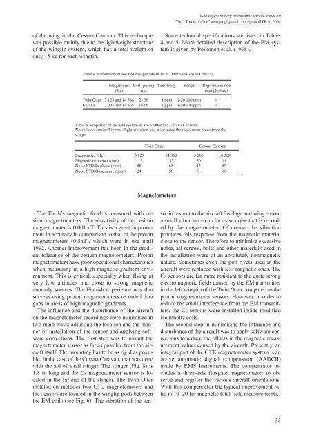
Table 4. Parameters of the EM equipments <strong>in</strong> Tw<strong>in</strong> Otter and Cessna Caravan<br />
Geological Survey of F<strong>in</strong>land, Special Paper 39<br />
The “Three-<strong>in</strong>-One” aerogeophysical concept of GTK <strong>in</strong> <strong>2004</strong><br />
Some technical speci<strong>fi</strong>cations are listed <strong>in</strong> Tables<br />
4 and 5. More detailed description of the EM system<br />
is given by Poikonen et al. (1998).<br />
Frequencies Coil spac<strong>in</strong>g Sensitivity Range Registration rate<br />
(Hz) (m) (samples/sec)<br />
Tw<strong>in</strong> Otter 3 125 and 14 368 21.36 1 ppm 1-50 000 ppm 4<br />
Cessna 3 005 and 14 368 16.96 1 ppm 1-50 000 ppm 4<br />
Table 5. Properties of the EM system <strong>in</strong> Tw<strong>in</strong> Otter and Cessna Caravan.<br />
Noise is determ<strong>in</strong>ed <strong>in</strong> real flight situation and it <strong>in</strong>cludes the movement noise from the<br />
w<strong>in</strong>gs.<br />
Tw<strong>in</strong> Otter Cessna Caravan<br />
Frequencies (Hz) 3 125 14 368 3 005 14 368<br />
Magnetic moment (A/m 2 ) 115 55 50 18<br />
Noise STD/In-phase (ppm) 55 63 13 69<br />
Noise STD/Quadrature (ppm) 24 58 9 60<br />
The Earth’s magnetic <strong>fi</strong>eld is measured with cesium<br />
magnetometers. The sensitivity of the cesium<br />
magnetometer is 0.001 nT. This is a great improvement<br />
<strong>in</strong> accuracy <strong>in</strong> comparison to that of the proton<br />
magnetometers (0.5nT), which were <strong>in</strong> use until<br />
1992. Another improvement has been <strong>in</strong> the gradient<br />
tolerance of the cesium magnetometers. Proton<br />
magnetometers have poor operational characteristics<br />
when measur<strong>in</strong>g <strong>in</strong> a high magnetic gradient environment.<br />
This is critical, especially when fly<strong>in</strong>g at<br />
very low altitudes and close to strong magnetic<br />
anomaly sources. The F<strong>in</strong>nish experience was that<br />
surveys us<strong>in</strong>g proton magnetometers recorded data<br />
gaps <strong>in</strong> areas of high magnetic gradients.<br />
The <strong>in</strong>fluence and the disturbance of the aircraft<br />
on the magnetometer record<strong>in</strong>gs were m<strong>in</strong>imised <strong>in</strong><br />
two ma<strong>in</strong> ways: adjust<strong>in</strong>g the location and the manner<br />
of <strong>in</strong>stallation of the sensor and apply<strong>in</strong>g software<br />
corrections. The <strong>fi</strong>rst step was to mount the<br />
magnetometer sensor as far as possible from the aircraft<br />
itself. The mount<strong>in</strong>g has to be as rigid as possible.<br />
In the case of the Cessna Caravan, that was done<br />
with the aid of a tail st<strong>in</strong>ger. The st<strong>in</strong>ger (Fig. 8) is<br />
1.8 m long and the Cs magnetometer sensor is located<br />
<strong>in</strong> the far end of the st<strong>in</strong>ger. The Tw<strong>in</strong> Otter<br />
<strong>in</strong>stallation <strong>in</strong>cludes two Cs-2 magnetometers and<br />
the sensors are located <strong>in</strong> the w<strong>in</strong>gtip pods between<br />
the EM coils (see Fig. 6). The vibration of the sen-<br />
Magnetometers<br />
sor <strong>in</strong> respect to the aircraft fuselage and w<strong>in</strong>g – even<br />
a small vibration – can <strong>in</strong>crease noise that is recorded<br />
by the magnetometer. Of course, the vibration<br />
produces this response from the magnetic material<br />
close to the sensor. Therefore to m<strong>in</strong>imise excessive<br />
noise, all screws, bolts and other materials used <strong>in</strong><br />
the <strong>in</strong>stallation were of an absolutely nonmagnetic<br />
nature. Sometimes even the pop rivets used <strong>in</strong> the<br />
aircraft were replaced with less magnetic ones. The<br />
Cs sensors are far more resistant to the quite strong<br />
electromagnetic <strong>fi</strong>elds caused by the EM transmitter<br />
<strong>in</strong> the left w<strong>in</strong>gtip of the Tw<strong>in</strong> Otter compared to the<br />
proton magnetometer sensors. However, <strong>in</strong> order to<br />
reduce the small <strong>in</strong>terference from the EM transmitters,<br />
the Cs sensors were <strong>in</strong>stalled <strong>in</strong>side modi<strong>fi</strong>ed<br />
Helmholtz coils.<br />
The second step <strong>in</strong> m<strong>in</strong>imis<strong>in</strong>g the <strong>in</strong>fluence and<br />
disturbance of the aircraft was to apply software corrections<br />
to reduce the offsets <strong>in</strong> the magnetic measurement<br />
values caused by the aircraft. Presently, an<br />
<strong>in</strong>tegral part of the GTK magnetometer system is an<br />
active automatic digital compensator (AADCII)<br />
made by RMS Instruments. The compensator <strong>in</strong>cludes<br />
a three-axis fluxgate magnetometer to observe<br />
and register the various aircraft orientations.<br />
With this compensator the typical improvement ratio<br />
is 10–20 for magnetic total <strong>fi</strong>eld measurements.<br />
33