Exploration and Optimization of Tellurium‐Based Thermoelectrics
Exploration and Optimization of Tellurium‐Based Thermoelectrics
Exploration and Optimization of Tellurium‐Based Thermoelectrics

Create successful ePaper yourself
Turn your PDF publications into a flip-book with our unique Google optimized e-Paper software.
5.1. Power Factor Measurements: ZEM‐3 Instrument<br />
The numerator <strong>of</strong> , , is known as the Power Factor <strong>and</strong> is the product <strong>of</strong> the Seebeck<br />
coefficient squared <strong>and</strong> the electrical conductivity. The ULVAC‐RIKO ZEM‐3 setup is the most frequently<br />
used instrument in the Kleinke group at this time, due to simultaneous measurement <strong>of</strong> S <strong>and</strong> σ over a<br />
wide temperature range – generally between ambient temperature <strong>and</strong> 673 K in this work because<br />
conventionally, materials are examined 100 K below their melting point to ensure the machine is not<br />
affected by melting compounds or vaporizing elements.<br />
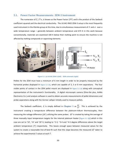
Figure 5.1 (a) ULVAC ZEM‐3 (left) ZEM schematic (right)<br />
Pellets for the ZEM must have a minimum <strong>of</strong> 6 mm length in order to be properly measured by the<br />
horizontal probes displayed in Figure 5.1 (b), which are capable <strong>of</strong> 3, 5 or 8 mm separations. The four<br />
visible points <strong>of</strong> contact in the ZEM pellet mount are displayed in Figure 5.1 (b) along with conceptual<br />
representation <strong>of</strong> the instrument’s functionality. A digital microscopic camera (Dino‐lite plus, AnMo<br />
Electronics Co.) <strong>and</strong> analysis s<strong>of</strong>tware is used to obtain accurate measurements <strong>of</strong> pellet dimensions <strong>and</strong><br />
probe separations along with the Vernier calliper initially used to measure pellets.<br />
The Seebeck coefficient, S, is simply defined in Chapter 1 as ∆<br />
. This is achieved by the<br />
instrument creating a temperature difference between the platinum‐iridium thermocouples, then<br />
measuring the voltage difference ∆ utilizing the same probes. ∆ is created by taking the average <strong>of</strong><br />
three manually input temperature targets for the internal platinum heater (Figure 5.1 (b)) which in this<br />
case are set to ‘10’, ‘15’ <strong>and</strong> ‘20’ K, leading to ~2‐3, ~3‐4 <strong>and</strong> ~4‐5 degree differences above the target<br />
ambient temperature respectively. This leaves enough space between measured values for the<br />
system to create a reasonable line‐<strong>of</strong>‐best‐fit such that this slope becomes the measured ∆ taken to<br />
achieve the experimental values at each .<br />
50<br />
∆