Exploration and Optimization of Tellurium‐Based Thermoelectrics
Exploration and Optimization of Tellurium‐Based Thermoelectrics
Exploration and Optimization of Tellurium‐Based Thermoelectrics

Create successful ePaper yourself
Turn your PDF publications into a flip-book with our unique Google optimized e-Paper software.
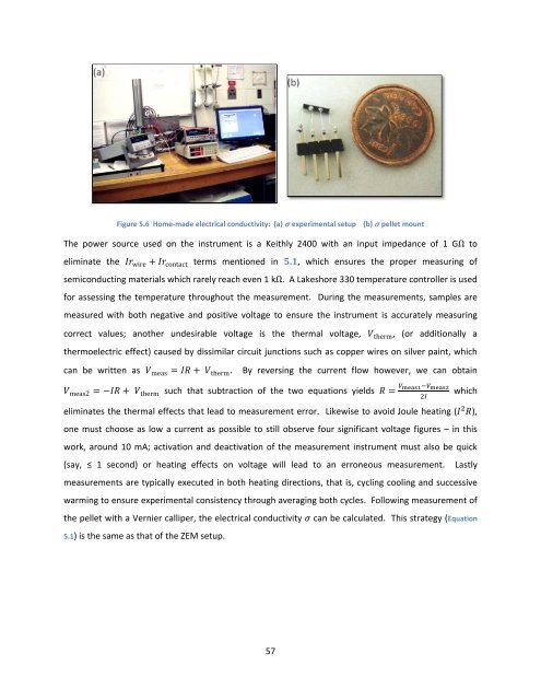
Figure 5.6 Home‐made electrical conductivity: (a) σ experimental setup (b) σ pellet mount<br />
The power source used on the instrument is a Keithly 2400 with an input impedance <strong>of</strong> 1 GΩ to<br />
eliminate the wire contact terms mentioned in 5.1, which ensures the proper measuring <strong>of</strong><br />
semiconducting materials which rarely reach even 1 kΩ. A Lakeshore 330 temperature controller is used<br />
for assessing the temperature throughout the measurement. During the measurements, samples are<br />
measured with both negative <strong>and</strong> positive voltage to ensure the instrument is accurately measuring<br />
correct values; another undesirable voltage is the thermal voltage, therm, (or additionally a<br />
thermoelectric effect) caused by dissimilar circuit junctions such as copper wires on silver paint, which<br />
can be written as meas therm. By reversing the current flow however, we can obtain<br />
meas2 therm such that subtraction <strong>of</strong> the two equations yields which<br />
<br />
eliminates the thermal effects that lead to measurement error. Likewise to avoid Joule heating (), one must choose as low a current as possible to still observe four significant voltage figures – in this<br />
work, around 10 mA; activation <strong>and</strong> deactivation <strong>of</strong> the measurement instrument must also be quick<br />
(say, ≤ 1 second) or heating effects on voltage will lead to an erroneous measurement. Lastly<br />
measurements are typically executed in both heating directions, that is, cycling cooling <strong>and</strong> successive<br />
warming to ensure experimental consistency through averaging both cycles. Following measurement <strong>of</strong><br />
the pellet with a Vernier calliper, the electrical conductivity can be calculated. This strategy (Equation<br />
5.1) is the same as that <strong>of</strong> the ZEM setup.<br />
57