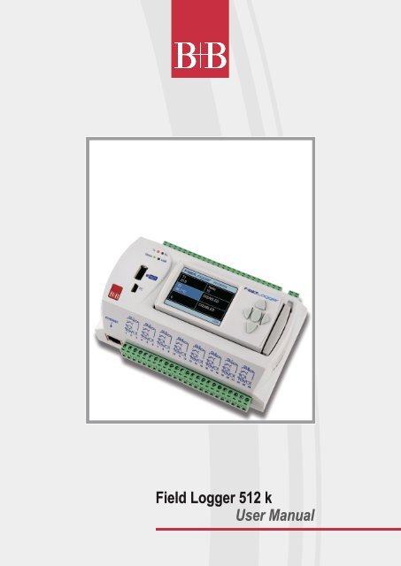
Field Logger 512 k User Manual - Temperatur-Shop
Field Logger 512 k User Manual - Temperatur-Shop
Field Logger 512 k User Manual - Temperatur-Shop

You also want an ePaper? Increase the reach of your titles
YUMPU automatically turns print PDFs into web optimized ePapers that Google loves.
<strong>Field</strong> <strong>Logger</strong> <strong>512</strong> k<br />
<strong>User</strong> <strong>Manual</strong>
INSTRUCTION MANUAL<br />
V1.0x F<br />
INTRODUCTION ................................................................................................................................................................. 3<br />
CONNECTIONS AND INSTALLATION ............................................................................................................................... 4<br />
MECHANICAL INSTALLATION ..................................................................................................................................... 4<br />
ATTACHING AND DETACHING THE FRONT COVER .......................................................................................... 8<br />
ATTACHING AND DETACHING THE HMI .............................................................................................................. 9<br />
ELECTRICAL CONNECTIONS ................................................................................................................................... 10<br />
RECOMMENDATIONS FOR INSTALLATION ....................................................................................................... 10<br />
POWER SUPPLY .................................................................................................................................................. 10<br />
DIGITAL I/OS ......................................................................................................................................................... 10<br />
RELAYS ................................................................................................................................................................. 11<br />
RS485 .................................................................................................................................................................... 11<br />
AUXILIAR POWER SUPPLY FOR POWERING TRANSMITTERS ....................................................................... 12<br />
ANALOG INPUTS .................................................................................................................................................. 12<br />
CONNECTIVITY RESOURCES .................................................................................................................................. 14<br />
FLAGS (LEDS) .................................................................................................................................................................. 15<br />
INSTALLING THE USB DRIVER ...................................................................................................................................... 16<br />
WINDOWS 7 ............................................................................................................................................................... 16<br />
DEFINITION AND SELECTION OF SERIAL PORT (COM) - WINDOWS ......................................................................... 20<br />
CONFIGURATION AND DATA DOWNLOAD SOFTWARE .............................................................................................. 21<br />
CONFIGURATION ...................................................................................................................................................... 22<br />
GENERAL CONFIGURATIONS ............................................................................................................................ 24<br />
RS485 INTERFACE CONFIGURATION ................................................................................................................ 25<br />
ETHERNET INTERFACE CONFIGURATION ....................................................................................................... 26<br />
ETHERNET INTERFACE CONFIGURATION - TCP/IP ................................................................................... 27<br />
ETHERNET INTERFACE CONFIGURATION – FTP ....................................................................................... 28<br />
ETHERNET INTERFACE CONFIGURATION - SMTP ..................................................................................... 29<br />
ETHERNET INTERFACE CONFIGURATION - E-MAIL RECEIVERS ............................................................. 29<br />
ETHERNET INTERFACE CONFIGURATION - SNMP .................................................................................... 30<br />
ETHERNET INTERFACE CONFIGURATION – HTTP .................................................................................... 31<br />
ETHERNET INTERFACE CONFIGURATION – MODBUS TCP ...................................................................... 32<br />
ANALOG CHANNELS CONFIGURATION............................................................................................................. 33<br />
ANALOG CHANNELS CONFIGURATION – CUSTOM CALIBRATION ........................................................... 35<br />
DIGITAL CHANNELS CONFIGURATION.............................................................................................................. 36<br />
REMOTE CHANNELS CONFIGURATION ............................................................................................................ 38<br />
VIRTUAL CHANNELS CONFIGURATION ............................................................................................................ 41<br />
ALARMS CONFIGURATION ................................................................................................................................. 42<br />
LOGS CONFIGURATION ...................................................................................................................................... 46<br />
DIAGNOSTICS ............................................................................................................................................................ 48<br />
DOWNLOAD ............................................................................................................................................................... 51<br />
PREFERENCES .......................................................................................................................................................... 59<br />
FIELDLOGGER OPERATION ........................................................................................................................................... 60<br />
ANALOG INPUTS ....................................................................................................................................................... 60<br />
DIGITAL INPUTS/OUTPUTS ...................................................................................................................................... 61<br />
OUTPUT RELAYS ....................................................................................................................................................... 62<br />
RS485 INTERFACE .................................................................................................................................................... 62<br />
REMOTE CHANNELS ................................................................................................................................................. 62<br />
VIRTUAL CHANNELS ................................................................................................................................................. 62<br />
USB INTERFACE ........................................................................................................................................................ 63<br />
USB DEVICE ......................................................................................................................................................... 64<br />
USB HOST ............................................................................................................................................................. 64<br />
ETHERNET INTERFACE ............................................................................................................................................ 64<br />
SENDING E-MAILS - SMTP .................................................................................................................................. 64<br />
WEB PAGES - HTTP ............................................................................................................................................. 65<br />
FILE TRANSFER - FTP ......................................................................................................................................... 66<br />
NOVUS AUTOMATION www.bubthermo.de www.fieldlogger.net 1/84 2
NETWORK MANAGEMENT - SNMP .................................................................................................................... 67<br />
DATA LOGGING AND DOWNLOAD ........................................................................................................................... 68<br />
ALARMS ...................................................................................................................................................................... 71<br />
DATA COMMUNICATION ................................................................................................................................................. 71<br />
HMI (HUMAN-MACHINE INTERFACE) ............................................................................................................................ 72<br />
“FAVORITES” SCREEN .............................................................................................................................................. 74<br />
“CHART” SCREEN ...................................................................................................................................................... 74<br />
“CHANNEL LIST” SCREEN ......................................................................................................................................... 74<br />
“ALARMS” SCREEN ................................................................................................................................................... 74<br />
“STATUS” SCREEN .................................................................................................................................................... 75<br />
“CONFIGURATION” SCREEN .................................................................................................................................... 75<br />
EQUIPMENT SOFTWARE UPDATE ................................................................................................................................ 77<br />
CLOCK BATTERY REPLACEMENT................................................................................................................................. 80<br />
SPECIFICATIONS ............................................................................................................................................................ 82<br />
WARRANTY ...................................................................................................................................................................... 84<br />
NOVUS AUTOMATION www.bubthermo.de www.fieldlogger.net 2/84 3
INTRODUCTION<br />
The <strong>Field</strong><strong>Logger</strong> is a high-resolution and high-speed data acquisition and logging equipment for analog and digital<br />
signals. The result of an advanced technological development, the product is distinguished in diverse aspects, such as<br />
high-performance, high-connectivity and easiness in the configuration and operation. This technology is presented as the<br />
ideal solution for applications that require flexibility and functionality for diverse standards of industrial networks.<br />
Its main features include:<br />
Analog inputs: 8<br />
Digital inputs/outputs: 8<br />
Relay outputs: 2<br />
2 MB internal memory<br />
SD Card interface (up to 16 GB)<br />
RS485 interface<br />
o Modbus RTU master and slave<br />
Ethernet services:<br />
USB:<br />
o DHCP<br />
o HTTP (web page)<br />
o FTP (client and server)<br />
o SMTP (e-mails sending)<br />
o SNMP<br />
o Modbus TCP<br />
o Host<br />
o Device<br />
HMI (human-machine interface – optional)<br />
There are four input channel types in the <strong>Field</strong><strong>Logger</strong>: analog, digital, remote and virtual. Analog and digital channels<br />
are those acquired directly by <strong>Field</strong><strong>Logger</strong> through their respective inputs. The remote channels are those acquired<br />
through Modbus RTU protocol, operating as master on its RS485 interface. Virtual channels are a special type of input<br />
channel where mathematical operations can be carried through, allowing the calculation of complex magnitudes from the<br />
measured information.<br />
The analog input channels are configurable for reading voltage, current, thermocouples, Pt100 and Pt1000 signals.<br />
These inputs count on the precision of a 24 bits A/D converter with high acquisition speed, which can reach 1000<br />
samples per second. The digital channels can be configured individually as inputs or outputs.<br />
The Ethernet interface allows data download and data access of the inputs and outputs, through services that can be<br />
individually enabled and configured. Through a web browser (HTTP), one can visualize the data of the enabled channel,<br />
diagnostics and general information of the <strong>Field</strong><strong>Logger</strong>. FTP client can be used for logging data downloads.<br />
<strong>Field</strong><strong>Logger</strong> can identify up to 32 distinct alarm conditions, allowing the triggering of outputs, sending e-mails or SNMP<br />
traps whenever an alarm condition is detected. All the information relative to the variables, status and diagnostics of the<br />
<strong>Field</strong><strong>Logger</strong> are available in Modbus registers that can be accessed through the Modbus TCP interface or the Modbus<br />
RTU interface available either through USB interface (device) or RS485 (when operating as slave).<br />
The USB Interface device is used for connection to a computer for configuration, monitoring or download. Whereas the<br />
USB interface host is used for connection of a USB flash drive, for data downloading from the logging memory.<br />
The data logging memory can be transferred by any of the interfaces to the configuration software, which allows the<br />
exportation for the most diverse data formats.<br />
When the indication of the magnitudes measured with the process is necessary, an exclusive color graphical display HMI<br />
(Human-Machine Interface) can be attached or installed remotely (optional).<br />
NOVUS AUTOMATION www.bubthermo.de www.fieldlogger.net 3/84 4
CONNECTIONS AND INSTALLATION<br />
MECHANICAL INSTALLATION<br />
When unpacking, remove the insulating film of the <strong>Field</strong><strong>Logger</strong> battery, located close<br />
below the cabinet according to Fig. 01, before carrying through the electrical wiring and<br />
configuration.<br />
Fig. 01 – Insulating film of the battery<br />
<strong>Field</strong><strong>Logger</strong> has a cabinet that is proper to be installed on a 35 mm rail.<br />
For the installation on the rail, you must pull out the two clamps located right below the connections of the channels,<br />
taking care not to remove them, as per Fig. 02.<br />
Note : In case you find it to be necessary, the connectors of the connections in the channels may be removed for<br />
installation of DIN rail.<br />
Fig. 02 - DIN rail installation<br />
NOVUS AUTOMATION www.bubthermo.de www.fieldlogger.net 4/84 5
Afterwards, fit in the <strong>Field</strong><strong>Logger</strong> to the rail according to Fig. 03.<br />
Fig. 03 - DIN rail installation<br />
And finally, push the two clamps until you hear a double click for the complete installation, as per Fig. 04.<br />
Fig. 04 - DIN rail installation<br />
NOVUS AUTOMATION www.bubthermo.de www.fieldlogger.net 5/84 6
Dimensions:<br />
Without HMI module:<br />
Fig. 05 – Dimensions of the <strong>Field</strong><strong>Logger</strong> without HMI module<br />
Fig. 06 – Dimensions of <strong>Field</strong><strong>Logger</strong> side without HMI module<br />
NOVUS AUTOMATION www.bubthermo.de www.fieldlogger.net 6/84 7
With HMI module (Optional):<br />
Fig. 07 – Dimensions of the <strong>Field</strong><strong>Logger</strong> with HMI module<br />
Fig. 08 – Dimensions of <strong>Field</strong><strong>Logger</strong> side with HMI module<br />
NOVUS AUTOMATION www.bubthermo.de www.fieldlogger.net 7/84 8
ATTACHING AND DETACHING THE FRONT COVER<br />
When detaching the front cover, pull the lever at the right side of the <strong>Field</strong><strong>Logger</strong> up to the end.<br />
When attaching it, insert the cover (left side first) and press its right side gently. After that, press the lever up to the end.<br />
Fig. 09 – Attaching and detaching <strong>Field</strong><strong>Logger</strong> front cover<br />
Fig. 10 – Attaching and detaching <strong>Field</strong><strong>Logger</strong> front cover (side view)<br />
NOVUS AUTOMATION www.bubthermo.de www.fieldlogger.net 8/84 9
ATTACHING AND DETACHING THE HMI<br />
When detaching the HMI, pull up the lever at the right side of the <strong>Field</strong><strong>Logger</strong> up to the end.<br />
When attaching it, insert the HMI (left side first) and press its right side until DB9 connectors are firmly connected. After<br />
that, press the lever down up to the end.<br />
Fig. 11 – Attaching and detaching <strong>Field</strong><strong>Logger</strong> HMI<br />
Fig. 12 – Attaching and detaching <strong>Field</strong><strong>Logger</strong> HMI (side view)<br />
NOVUS AUTOMATION www.bubthermo.de www.fieldlogger.net 9/84 10
ELECTRICAL CONNECTIONS<br />
Fig. 13 - <strong>Field</strong><strong>Logger</strong> front panel<br />
<strong>Field</strong><strong>Logger</strong> has two rows of terminals for diverse connections; among them are the following items: Ethernet, input<br />
connections, power supply, output relays, output for stand-by power supply, digital inputs and serial communication. This<br />
information is identified in the box of <strong>Field</strong><strong>Logger</strong> according to Fig. 14 and Fig. 15:<br />
RECOMMENDATIONS FOR INSTALLATION<br />
Fig. 14 - Upper side connections<br />
Fig. 15 - Lower side connections<br />
Input signal leads must be installed in grounded conduits and away from power or contactor wires.<br />
Instruments must be powered only by an exclusive power supply.<br />
Installing RC filters (47 and 100 nF, serial) is strongly recommended at contactor coils or any other inductors.<br />
System failure should always be taken into account when designing a control panel to avoid irreversible damage to<br />
equipment or people. The RL1 and RL2 output relays, used as alarms, do not warrant total protection.<br />
Wires section: minimum gauge 0.14 mm².<br />
POWER SUPPLY<br />
The terminals 25 and 26 indicate the main power supply of <strong>Field</strong><strong>Logger</strong>.<br />
DIGITAL I/OS<br />
There are eight I/Os that can be individually configured as inputs or outputs. There is a terminal for the positive signal of<br />
each I/O, but the negative terminal of all of them is common (there is no insulation among the channels).<br />
NOVUS AUTOMATION www.bubthermo.de www.fieldlogger.net 10/84 11
Inputs:<br />
When configured as inputs, they may be connected to voltage outputs (please check the acceptable levels in the<br />
Specifications section), dry-contact outputs and NPN outputs. Care must be taken when connecting multiple outputs<br />
because of the lack of insulation between the Fiedl<strong>Logger</strong> inputs.<br />
Outputs:<br />
Fig. 16 - Voltage connection Fig. 17 –Dry-contact connection Fig. 18 – NPN Connection<br />
When configured as outputs, they can activate limited power loads (please check the Specifications section).<br />
RELAYS<br />
Fig. 19 - Connection of a load RL to a digital output<br />
<strong>Field</strong><strong>Logger</strong> has 2 relays that can be used in the activation of electrical loads (please check the Specifications section).<br />
For each relay, we have the common terminal, NC (normally closed) terminal and the NO (normally open) terminal.<br />
When deactivated, the relay common is in contact with the NC terminal. When activated, the common is in contact with<br />
the NO terminal.<br />
RS485<br />
The Interface RS485 of the <strong>Field</strong><strong>Logger</strong> has terminals for the 3-wire communication, including the common. The<br />
connection in a Modbus network will depend if the device is configured to operate as a master or a slave.<br />
Master<br />
NOVUS AUTOMATION www.bubthermo.de www.fieldlogger.net 11/84 12
Slave<br />
AUXILIAR POWER SUPPLY FOR POWERING TRANSMITTERS<br />
There is a 24 Vdc power supply available in the <strong>Field</strong><strong>Logger</strong> for powering transmitters in the field. This auxiliar power<br />
supply is electrically insulated from the other <strong>Field</strong><strong>Logger</strong> terminals.<br />
Below is the correct way to use the auxiliar power supply for powering 4-20 mA transmitters (2-wire).<br />
ANALOG INPUTS<br />
Pt100/Pt1000 connection<br />
Fig. 20 – Auxiliar power supply powering 4-20 mA (2-wire) transmitters<br />
The connection for the channels is made in the terminals in accordance with the figure at<br />
the left. The 3-wire connection from the Pt100 sensing element to the <strong>Field</strong><strong>Logger</strong> input<br />
guarantees the cancellation of the error caused by the resistance of the wires. All three<br />
wires must have the same gauge and length.<br />
For the two-wire Pt100, interconnect terminals 1 and 2.<br />
NOVUS AUTOMATION www.bubthermo.de www.fieldlogger.net 12/84 13
Thermocouple connection<br />
Voltage (mV) connection<br />
Voltage (V) connection<br />
Current (mA) connection<br />
The connection for the channels is made in the terminals in accordance with the figure at<br />
the left. Please observe the correct connection polarity.<br />
Cables used for connecting thermocouples must have the same thermoelectric<br />
characteristics of the used thermocouple (compensation cable or extension cable), and<br />
also must be connected with the correct polarity.<br />
The non-use of compensation cables or the use with the incorrect polarity can cause great<br />
measurement errors.<br />
The connection for the channels is made in the terminals in accordance with the figure at<br />
the left. Please observe the correct polarity of the connection.<br />
The connection for the channels is made in the terminals in accordance with the figure at<br />
the left. Please observe the correct polarity of the connection.<br />
The connection for the channels is made in the terminals in accordance with the figure at<br />
the left. Please observe the correct polarity of the connection.<br />
NOVUS AUTOMATION www.bubthermo.de www.fieldlogger.net 13/84 14
CONNECTIVITY RESOURCES<br />
USB Connection<br />
PC Connection<br />
SD card connection<br />
Ethernet<br />
DB9 connection for HMI (Optional)<br />
Fig. 21 - <strong>Field</strong><strong>Logger</strong> connectivity resources<br />
Interface used for a USB drive connection, for downloading data from the logging memory.<br />
Interface used for connection to a computer for configuration, monitoring or data download.<br />
Interface used for SD card expansion. The data from the logging memory can be transferred<br />
by any of the interfaces to the configuration software, which allows the exportation for the<br />
most diverse data formats.<br />
Interface used for Ethernet 10/100 communication. It is recommended to use a category 5 (or<br />
better) cable in a RJ45 connector.<br />
The Ethernet connector of the <strong>Field</strong><strong>Logger</strong> has two LEDS for luminous indication: the green<br />
LED (on the left side) lights indicating the connection to the Ethernet network; the yellow LED<br />
(on the right side) flashes indicating that there is data traffic in the interface.<br />
Connection for installation of HMI (Human–Machine Interface) of the <strong>Field</strong><strong>Logger</strong> for<br />
indication of signals measured in the process.<br />
NOVUS AUTOMATION www.bubthermo.de www.fieldlogger.net 14/84 15
FLAGS (LEDS)<br />
Tx/Rx flags<br />
Status / USB flags<br />
They signal transmission and reception of data by the RS485/Modbus interface, no matter if it<br />
is configured to operate in master or slave mode.<br />
When connecting the equipment, both leds flash two times and remain extinguished until all<br />
the initialization has been completed.<br />
The Status flag remains ON in normal conditions. When it is logging, the same will have to<br />
flash two times for each 3 seconds. In error cases, this led will be flashing 3 times in each 8<br />
seconds.<br />
In the error cases, please check if the clock of the <strong>Field</strong><strong>Logger</strong> has the correct date and<br />
time. If they are wrong, probably the battery of the clock has run low and needs to be<br />
replaced. If it is OK, try rebooting the machine by turning off its power supply and restarting it<br />
after 10 seconds. If the led insists on the error indication, there may be something wrong with<br />
your <strong>Field</strong><strong>Logger</strong>.<br />
The USB flag remains ON only while a cable is connected in the USB device or while the<br />
USB flash drive is plugged into the USB host interface. The following exceptions are:<br />
Download errors via USB flash drive: flash drive with insufficient writing space,<br />
inability to write in the flash drive (write protected) or flash drive not compatible<br />
(sector different from <strong>512</strong> bytes, for example), the USB led flashes while the error<br />
condition remains (typically, until the flash drive has been removed). Check the "USB<br />
Interface" section in the chapter "<strong>Field</strong><strong>Logger</strong> Operation" for more details.<br />
At the end of the download, if everything is correct, the USB flag remains ON until the<br />
flash drive has been removed from the equipment.<br />
NOVUS AUTOMATION www.bubthermo.de www.fieldlogger.net 15/84 16
INSTALLING THE USB DRIVER<br />
When installing the configuration software, the USB driver is automatically installed. Anyway, if you need to install the<br />
driver without depending on the software, this can be done by following the procedure described below.<br />
The following installation steps may vary from PC to PC, even for the same operating system version. The steps and<br />
screens that follow below are only for guidance purposes.<br />
WINDOWS 7<br />
1. Connect <strong>Field</strong><strong>Logger</strong> in a USB port on your computer. Windows will try to install a driver automatically and will not<br />
succeed, because the necessary driver is not in its standard library.<br />
2. Click on "Start>> Control Panel". Click on "System" and, later on, on the "Device Manager".<br />
NOVUS AUTOMATION www.bubthermo.de www.fieldlogger.net 16/84 17
3. Locate the <strong>Field</strong><strong>Logger</strong> (probably with an icon with an exclamation mark next to it) and double-click on it.<br />
4. Click on the button "Update Driver...".<br />
NOVUS AUTOMATION www.bubthermo.de www.fieldlogger.net 17/84 18
5. Ask to "Browse my computer for driver software".<br />
6. Enter the path of the folder where the drivers are located (the product CD or folder where you saved them when<br />
downloaded from the site.)<br />
7. Wait for the installation to take start.<br />
NOVUS AUTOMATION www.bubthermo.de www.fieldlogger.net 18/84 19
8. Windows will complain that it can not verify the editor of this driver. Confirm to install anyway!<br />
9. A message indicating successful installation will display.<br />
10. Returning to the Device Manager screen, you can check which virtual serial port is allocated to the <strong>Field</strong><strong>Logger</strong>.<br />
NOVUS AUTOMATION www.bubthermo.de www.fieldlogger.net 19/84 20
DEFINITION AND SELECTION OF SERIAL PORT (COM) - WINDOWS<br />
The serial port associated with <strong>Field</strong><strong>Logger</strong> is automatically defined by the operating system a few moments after<br />
connecting the <strong>Field</strong><strong>Logger</strong>. The user can easily identify or change the COM port associated with <strong>Field</strong><strong>Logger</strong>:<br />
Control Panel / System / Hardware / Device Manager / COM & LPT Ports<br />
Select the device "USB Serial Port" corresponding to the <strong>Field</strong><strong>Logger</strong> and click on "Properties". Select "Port Settings"<br />
guide and click on "Advanced". In the "COM Port Number", select the serial port to be associated with <strong>Field</strong><strong>Logger</strong>.<br />
Some serial ports can be checked while being used (In Use). Just select one of these ports if you know that it is not<br />
being used by another peripheral device on your computer.<br />
In some cases, the serial ports can be checked as in use even when the associated device is no longer installed on your<br />
computer. In this case it is safe to associate this port to <strong>Field</strong><strong>Logger</strong>. The following figure presents the view of the device<br />
manager containing a <strong>Field</strong><strong>Logger</strong>, and the screens where the property screens where you can reset the associated<br />
COM port.<br />
NOVUS AUTOMATION www.bubthermo.de www.fieldlogger.net 20/84 21
CONFIGURATION AND DATA DOWNLOAD SOFTWARE<br />
The configuration software (Configurator) allows you to make the configuration of <strong>Field</strong><strong>Logger</strong>, download and export<br />
logging data and read input channels and status information. This chapter is intended to show and explain software<br />
usage. The use of <strong>Field</strong><strong>Logger</strong> with all its features will be detailed in the chapter "<strong>Field</strong><strong>Logger</strong> Operation”.<br />
On the main screen, you should choose the function that you want to run, as it is shown below:<br />
Configuration: Allows you to change the <strong>Field</strong><strong>Logger</strong> configuration.<br />
Diagnostics: Allows you to read the values of the enabled channels, the status of configured alarms and general<br />
information and device status.<br />
Download: Allows you to perform data download of <strong>Field</strong><strong>Logger</strong> logging memory, view and export them in<br />
various formats.<br />
Preferences: It allows modifying some software options.<br />
NOVUS AUTOMATION www.bubthermo.de www.fieldlogger.net 21/84 22
CONFIGURATION<br />
On the configuration screen, you can select one of the following options, as they are described below:<br />
Read Configuration: Reads the current configuration of a <strong>Field</strong><strong>Logger</strong>.<br />
New Configuration: Creates a configuration from the scratch.<br />
Open Configuration: Loads the previously configuration saved to a file.<br />
If the chosen option was to create a new configuration, you must specify a file where this configuration will be saved.<br />
Once the configuration has been loaded into the software (originated from a device, a file, or simply created from the<br />
scratch, according to the selected option), then one should make the desired configuration. For this, there is a sequence<br />
of screens with various parameters arranged by functionality.<br />
Each time you try to move onto the next screen (via the "Next" button), a consistency of the configured parameters is<br />
done. In case there is any problem with any parameter, an error window is displayed and the symbol " ” shows up<br />
next to the field with the problem.<br />
NOVUS AUTOMATION www.bubthermo.de www.fieldlogger.net 22/84 23
The icon bar at the bottom of the window has icons for the following functions, as they are described below:<br />
Back: It allows coming back to the previous configuration screen.<br />
Save: Saves the current configuration to a file. If a file has not yet been associated with this configuration, it<br />
opens a dialog screen for the user to choose the name and location of the file.<br />
Language: Changes the language of the software among Portuguese, English and Spanish.<br />
Connection: Allows the connection to the equipment (opens a window for the interface selection) when it is<br />
disconnected and the disconnection when it is connected.<br />
Load Screen Initial Configuration: Undo the changes introduced by the user, returning to the initial configuration<br />
of the current screen.<br />
Cancel: Closes the current configuration.<br />
Next: Performs the consistency of the current configuration screen and, if everything is OK, goes to the next<br />
screen.<br />
Icon toolbar<br />
NOVUS AUTOMATION www.bubthermo.de www.fieldlogger.net 23/84 24
GENERAL CONFIGURATIONS<br />
The first screen shows some general parameters of configuration for the <strong>Field</strong><strong>Logger</strong>:<br />
Tag (name) to be given to the equipment (maximum of 16 characters).<br />
When using a HMI with the <strong>Field</strong><strong>Logger</strong>, please indicate the level of access that the operator will get through the<br />
HMI:<br />
o No HMI access: Prevents the use of the HMI, because no parameter can be viewed by it in this<br />
<strong>Field</strong><strong>Logger</strong>.<br />
o Parameters reading: HMI can be used only to view the channels and status of the <strong>Field</strong><strong>Logger</strong>, not<br />
allowing any type of configuration.<br />
o HMI configuration and overall reading: HMI can have its own parameters configured, besides viewing<br />
the channels and status of the <strong>Field</strong><strong>Logger</strong>.<br />
o Overall configuration and reading: HMI can be used to configure parameters (its own and some of<br />
<strong>Field</strong><strong>Logger</strong>), in addition to viewing the channels and status of the <strong>Field</strong><strong>Logger</strong>.<br />
Enabling data download by using a USB flash drive: it enables or disables the data download by using a USB<br />
flash drive. When enabled, it also allows indicating the priority in case of a USB flash drive without enough space<br />
to download all demanded data: more recent data or older data. In addition, you can configure the number of days<br />
(from the day of download, if the priority is the latest, or from the oldest data, if the priority is the oldest) that you<br />
want to download. Because of the fact that we do not make a copy of all data from the equipment’s memory<br />
(which, in the case of SD cards, can be a lot of data), this can accelerate download time significantly.<br />
General Configurations<br />
NOVUS AUTOMATION www.bubthermo.de www.fieldlogger.net 24/84 25
RS485 INTERFACE CONFIGURATION<br />
Next configuration screen is the RS485 Interface screen. On this screen, you should choose the type of behavior of this<br />
interface: whether it will be a Modbus RTU slave, a Modbus RTU master or it shall not be used at all. It is recommended<br />
to disable the interface if it is not used.<br />
When it is used as a slave, you must configure your Modbus address, the baud rate, parity and number of stop bits.<br />
When it is used as a master, it is not necessary to configure the Modbus address (only valid for the slaves). Moreover, in<br />
this case, the configuration of Modbus network, where it says which registers are read from what slaves, will be carried<br />
through later on, on the Remote Channels screen.<br />
Interface RS485<br />
NOVUS AUTOMATION www.bubthermo.de www.fieldlogger.net 25/84 26
ETHERNET INTERFACE CONFIGURATION<br />
The configuration of the Ethernet interface should be carried through on the next screen. If it is desired not to use this<br />
interface, it is recommended to disable it, as shown in the following figure.<br />
Disabled Ethernet Interface<br />
NOVUS AUTOMATION www.bubthermo.de www.fieldlogger.net 26/84 27
ETHERNET INTERFACE CONFIGURATION - TCP/IP<br />
Once the interface is enabled, the buttons on the left allow you to enable and configure each of the services offered by<br />
this interface. The icon on the right of each button shows whether the related service is enabled or not.<br />
The first configuration to be made is the selection of using fixed IP or DHCP and, in the case of fixed IP, to choose the<br />
parameters relating to it, such as <strong>Field</strong><strong>Logger</strong> IP, the subnet mask and default gateway.<br />
Moreover, we must choose whether or not to use DNS, which can be used to connect to the e-mail server or FTP server<br />
(when <strong>Field</strong><strong>Logger</strong> is the FTP client for the daily download of data through this service). If so, you must configure the<br />
DNS server's IP number or, if the DHCP option has been selected, you can choose to search for the DNS server’s IP<br />
from the DHCP server.<br />
Ethernet Interface - TCP/IP Configuration<br />
NOVUS AUTOMATION www.bubthermo.de www.fieldlogger.net 27/84 28
ETHERNET INTERFACE CONFIGURATION – FTP<br />
The FTP button allows you to configure the options related to the FTP services. There are two types of FTP related<br />
functionality foreseen in the <strong>Field</strong><strong>Logger</strong>: client and server.<br />
As a server, <strong>Field</strong><strong>Logger</strong> allows for an external client to connect to it in order to download logged data, both from the SD<br />
card as well as from the internal memory. For this, you must configure the connection and access data, like user name,<br />
password and port for the connection.<br />
As a client, once a day at a set time, it will connect to a FTP server to send the data from its logging memory (internal or<br />
SD card). This way, you must configure the access parameters so <strong>Field</strong><strong>Logger</strong> will be able to access the server, like<br />
user and password, in addition to the IP address or server name (in case you enabled the DNS – name being up to 50<br />
characters) and the server’s port.<br />
Ethernet Interface - FTP Configuration<br />
NOVUS AUTOMATION www.bubthermo.de www.fieldlogger.net 28/84 29
ETHERNET INTERFACE CONFIGURATION - SMTP<br />
The SMTP button opens the parameters related to sending e-mails. The <strong>Field</strong><strong>Logger</strong> allows that, in situations of alarm,<br />
e-mails may be sent to multiple receivers. On this screen, then the parameters related to the access to the e-mail server<br />
must be configured, such as its IP address or server name (in case you enabled the DNS – name being up to 50<br />
characters), in addition to the user (maximum of 20 characters) and password (maximum of 12 characters).<br />
Finally, you must configure the parameters of the e-mail to be sent in case of an alarm event. This e-mail has a subject<br />
(maximum of 32 characters) and has a part of the message body that is user defined (up to 64 characters) and that is the<br />
same for all alarms. The e-mail of the sender (maximum of 50 characters) and the e-mails of the receivers (maximum of<br />
50 characters for each one) must also be configured.<br />
Ethernet Interface - SMTP Configuration<br />
ETHERNET INTERFACE CONFIGURATION - E-MAIL RECEIVERS<br />
For the insertion of the of e-mail receivers, you should click on the button "Edit List". A new window will open, allowing for<br />
the inclusion and removal of e-mails from the receivers list. All potential receivers of alarm e-mails must be included in<br />
this window. The decision of which alarms will be sent to which receivers will be made later, on alarms configuration<br />
screen!<br />
Ethernet Interface - Configuration of E-mail Receivers<br />
NOVUS AUTOMATION www.bubthermo.de www.fieldlogger.net 29/84 30
ETHERNET INTERFACE CONFIGURATION - SNMP<br />
The SNMP protocol can be enabled and configured by clicking on the SNMP button. SNMP in the <strong>Field</strong><strong>Logger</strong> is readonly.<br />
Thus, you should set up the community for access (maximum of 16 characters) and connection port.<br />
For using traps, you must enable them separately. You should also set up the IP address and destination port for the<br />
traps.<br />
Ethernet Interface – SNMP Configuration<br />
NOVUS AUTOMATION www.bubthermo.de www.fieldlogger.net 30/84 31
ETHERNET INTERFACE CONFIGURATION – HTTP<br />
The HTTP button enables <strong>Field</strong><strong>Logger</strong> to serve a web page with some data from the equipment. This page has an autorefresh<br />
parameter, indicating to the navigator software (browser) that the page should be reloaded with updated data<br />
from time to time. For this, the configuration needed is just the connection port and the time in seconds between page<br />
updates.<br />
Ethernet Interface – HTTP Configuration<br />
NOVUS AUTOMATION www.bubthermo.de www.fieldlogger.net 31/84 32
ETHERNET INTERFACE CONFIGURATION – MODBUS TCP<br />
Finally, the Modbus TCP button allows you to enable the Modbus TCP communication protocol, used to read and write<br />
data in <strong>Field</strong><strong>Logger</strong>. Among others, the Configurator software itself uses this protocol to communicate with <strong>Field</strong><strong>Logger</strong><br />
in order to read and write configuration parameters, view diagnostic data and download logging data, when Ethernet<br />
interface has been selected.<br />
Ethernet Interface - Modbus TCP Configuration<br />
NOVUS AUTOMATION www.bubthermo.de www.fieldlogger.net 32/84 33
ANALOG CHANNELS CONFIGURATION<br />
On the next screen, you must configure the analog channels to be used. Each channel is individually configured, so you<br />
should first select which channel to be configured in the list on the left.<br />
After the channel has been selected, you must configure its parameters on the right. For each channel, you must<br />
configure a tag (name with a maximum of 16 characters) and an input type. Depending on the selected input type, the<br />
indication limits must also be configured. For temperature sensors, you must choose whether the indication will be in<br />
Celsius or Fahrenheit, for the others, you can type a string for the unit (maximum of 10 characters).<br />
There is also the option to enter an error value to be displayed when an error is detected on the input signal, such as a<br />
ruptured 4-20 mA loop or a Pt100 with a broken cable. There is also the possibility to configure a digital filter for the input<br />
channel (the higher the value is, more filtered is the indication of the channel, making the response more immune to<br />
noises on the input signal, but also slower on variations - maximum filter value is 20).<br />
There is the option of using the Custom Calibration. This feature allows up to 10 pairs of points to be inserted in a<br />
“correction table” (per analog input) in the device, creating segments for adjustments to the indicated value. Further<br />
details in the "<strong>Field</strong><strong>Logger</strong> Operation” chapter.<br />
The number of decimal places to be displayed must also be configured. This parameter refers to the following cases<br />
described below:<br />
Reading the value of the channel via Modbus 16 bits registers (INT16 with signal). Further details in the document<br />
"<strong>Field</strong><strong>Logger</strong> – Modbus”.<br />
Reading the value of the channel via HMI.<br />
Reading the value of the channel through the HTML page generated by <strong>Field</strong><strong>Logger</strong> itself (HTTP service on the<br />
Ethernet interface).<br />
Reading the value of the channel through the OID reading of SNMP protocol (SNMP service of Ethernet<br />
interface).<br />
Reading the alarm value related to the channel when receiving e-mails from the <strong>Field</strong><strong>Logger</strong> (SMTP service on<br />
the Ethernet interface).<br />
Analog Channels - Configuration of a temperature channel<br />
NOVUS AUTOMATION www.bubthermo.de www.fieldlogger.net 33/84 34
Analog Channels – Configuration of a linear channel<br />
NOVUS AUTOMATION www.bubthermo.de www.fieldlogger.net 34/84 35
ANALOG CHANNELS CONFIGURATION – CUSTOM CALIBRATION<br />
In the "Custom Calibration" button, you can enter up to 10 custom calibration points for each analog channel. The correct<br />
way to do this is as described below:<br />
1. Disable the custom calibration of the channel to be adjusted, deleting all points configured for it, and apply this setting<br />
in the device.<br />
2. In the points to be adjusted, apply the standard value and write down the value indicated by the equipment.<br />
3. Afterwards, insert the pairs of Custom Calibration points (injected value and indicted value) and apply the<br />
configuration in the equipment.<br />
Analog Channels - Custom Calibration<br />
Analog Channels - Custom Calibration<br />
NOVUS AUTOMATION www.bubthermo.de www.fieldlogger.net 35/84 36
DIGITAL CHANNELS CONFIGURATION<br />
After configuring the analog channels, it is time to configure the digital channels and relays. Just as it is in the analog<br />
ones, on the list on the left, you can select which channel is to be configured.<br />
Each channel can be configured as an input or an output. As an input, you can enable it or not. If it is disabled, it will not<br />
appear as an option in the logs, alarms, in the virtual channels or even in the HMI. Once the input has been enabled, you<br />
must provide a unique tag (name - maximum of 16 characters) for this channel. You should also provide a value to be<br />
displayed when in "0" level (low voltage level or contact closed at the input) and another value to be indicated when in "1"<br />
level (high voltage level or contact open at the input). These values will be shown in the channel reading. Finally, you can<br />
optionally configure a unit (maximum 10 characters) for the input.<br />
Digital channels - Configuring an input<br />
NOVUS AUTOMATION www.bubthermo.de www.fieldlogger.net 36/84 37
When configured as an output, you should indicate whether this output may be triggered by <strong>Field</strong><strong>Logger</strong> alarms or if it<br />
will be controlled by external Modbus commands, coming from a PLC or a SCADA software, for example.<br />
Digital channels – Configuring an output<br />
The two <strong>Field</strong><strong>Logger</strong> relays are also configured on this screen and their configuration is similar to that of other digital<br />
outputs. You should just indicate whether they are triggered by internal alarms or external Modbus commands.<br />
Digital Channels - Configuring a relay<br />
NOVUS AUTOMATION www.bubthermo.de www.fieldlogger.net 37/84 38
REMOTE CHANNELS CONFIGURATION<br />
The configuration of remote channels, made on the next screen, is only available when the RS485 interface has been<br />
configured as a Modbus master. In the case of the RS485 interface having been configured as a slave or disabled, the<br />
remote channels screen shall display a message indicating the inability of its configuration.<br />
Remote Channels Disabled<br />
NOVUS AUTOMATION www.bubthermo.de www.fieldlogger.net 38/84 39
If the RS485 interface was configured as Modbus master, the following screen will be displayed. You should set up a tag<br />
(name - maximum of 16 characters), unique for each channel, and optionally a unit (maximum of 10 characters) for the<br />
reading value.<br />
In addition, for each channel, you should set up which network slave is to be read, what Modbus command sholud be<br />
used and what is the initial register to be read from the slave. In the current version, the number of registers is always<br />
"1", which means that you can not do block reading.<br />
An error value must also be configured. This value is shown on the channel when there is a problem, for example, a<br />
communication error with the slave.<br />
At the end of the channel configuration, you must click on the “Add” button in order to enter the channel in the list to the<br />
left. If you want to remove a channel from the list, you must select it from the list and click on "Remove".<br />
Remote Channels - Setting up a channel<br />
NOVUS AUTOMATION www.bubthermo.de www.fieldlogger.net 39/84 40
At the bottom of the screen there are the general parameters of the Modbus Master configuration. The reading interval,<br />
given in tenths of seconds (maximum 18,000, equivalent to 30 minutes) is the time that you want <strong>Field</strong><strong>Logger</strong> to make a<br />
new scan of all configured remote channels. The number of trials (valid range: 1 to 10) is how many attempts are made<br />
in sequence for the reading of each channel (if the communication fails in all attempts it will be displayed the error value<br />
set up for the channel).<br />
The maximum response time (valid range: 2 to 10,000 ms) indicates how long, after sending the command from the<br />
master, it will wait for the slave’s response. If the answer does not come within this time, this will be considered a<br />
communication error and a new try (if configured) will be carried through. The time between commands (valid range:<br />
1000 to 5000 ms) indicates how much time should be awaited by <strong>Field</strong><strong>Logger</strong> between receiving the slave’s response<br />
and sending the next command.<br />
Remote Channels - Inserting a channel in the list<br />
NOVUS AUTOMATION www.bubthermo.de www.fieldlogger.net 40/84 41
VIRTUAL CHANNELS CONFIGURATION<br />
The following screen allows the configuration of the virtual channels. Each virtual channel is the result of a mathematical<br />
or logical operation and must be configured by selecting a unique tag (name - maximum of 16 characters) for this<br />
channel. You should then select the first channel that will serve as the operand (depending on the selected operation, it<br />
will be the only one). When you select "Constant Value", you will be able to assign a numeric value to the virtual channel<br />
(this value can be used as an operand in other virtual channels). After that, you must choose the operation to be<br />
performed and which channel is to be used as the second operand in the operation (when previously chosen "Constant<br />
Value", there should be placed the numeric value of the channel).<br />
Finally, one should choose a unit (optional - maximum of 10 characters) for the channel, plus an error value and the<br />
number of decimal places desired in the indication of the same one. When clicking on "Add", the newly configured<br />
channel is added to the list of virtual channels.<br />
When a virtual channel is configured, all enabled input channels are available for use as operands, including virtual<br />
channels already placed in the list. This enables us to generate relatively complex expressions, using the result of an<br />
operation as an operand in another one. For more details, please see the section "Virtual Channels" under the chapter<br />
"<strong>Field</strong><strong>Logger</strong> Operation”.<br />
Clicking on any virtual channel in the list, its parameters are loaded at the top fields. To delete a channel, you must select<br />
it from the list and click on "Remove". To delete all the virtual channels, you must click on "Remove All".<br />
Virtual Channels<br />
NOVUS AUTOMATION www.bubthermo.de www.fieldlogger.net 41/84 42
ALARMS CONFIGURATION<br />
After setting up all channels, you can configure alarms in order to indicate error or exception conditions. For this, we<br />
must choose which channel must be used for the alarm, what is the alarm condition and what is the set point (trigger<br />
value for the alarm). For example, you can select an analog temperature channel to alarm when the temperature<br />
exceeds a critical threshold, or a digital input channel to alarm when your state is different from the expected value.<br />
A hysteresis can be configured to prevent a marginal condition, such as an input that hovers around the set point value,<br />
which remains generating multiple alarm events. In some cases, like when the alarm channel is a digital input, the<br />
hysteresis does not make much sense and should be maintained at “0”.<br />
Whenever a digital channel is used for an alarm, hysteresis shall not be used (must be<br />
configured with “0”)!<br />
Each alarm can have one or more associated actions. You should then choose what actions should be performed on the<br />
occurrence of an alarm (different actions organized by tabs). The available actions are the activation of relays, the<br />
activation of digital outputs (assuming they are configured to be triggered by an alarm), the sending of e-mails to one or<br />
more receivers (selected from among the ones configured on the Ethernet interface configuration page), sending a<br />
SNMP trap and the start and/or stop of the loggings. Finally, when everything is set up, you should include the alarm in<br />
the list clicking on the “Add” button.<br />
By clicking on an alarm from the list on the left, its parameters are loaded into the fields on the right. To delete a channel<br />
from the list, you must select it from the list and click on "Remove". To modify some parameter of an alarm, you must<br />
select it from the list, change whatever you want and click on "Modify". The button "Delete all" deletes all alarms in the<br />
list.<br />
Alarms Configuration - Relays selection<br />
NOVUS AUTOMATION www.bubthermo.de www.fieldlogger.net 42/84 43
Alarms Configuration - Digital outputs selection<br />
Alarms Configuration - Logs control configuration<br />
NOVUS AUTOMATION www.bubthermo.de www.fieldlogger.net 43/84 44
Alarms Configuration - E-mail receivers selection<br />
Alarms Configuration - Enabling SNMP traps<br />
NOVUS AUTOMATION www.bubthermo.de www.fieldlogger.net 44/84 45
Alarms Configuration - Alarm added to the list<br />
NOVUS AUTOMATION www.bubthermo.de www.fieldlogger.net 45/84 46
LOGS CONFIGURATION<br />
The last page of the configuration is about logging. If data logging are not desired, you should disable it.<br />
Logs configuration should be carried through initially by choosing the start mode and stop mode for the logging process.<br />
If, on the previous screen, the start and/or stop of the loggings were assigned to one or two alarms, this option is sealed<br />
and can not be changed on the Logs screen.<br />
If you want to use the start and/or stop of the loggings through Modbus commands, you must enable these options. In<br />
addition, you must select which is the memory where the logging data must be stored: in the internal flash (<strong>512</strong>k logs) or<br />
in the SD card inserted by the user.<br />
Finally, you must select which channels you want to log and what is the desired log rate. The channels can be selected<br />
for logging moving them from the left side column (available channels) to the right side column (channels to be logged).<br />
A maximum of 100 channels can be logged, but keep in mind that the more channels to be logged, the slower is the<br />
logging rate that can be used.<br />
The logging rate is given as a logging interval and it is common to all channels. In other words, a rate of 1 second means<br />
that all channels selected for registration will be logged once per second. Although the equipment allows for a rate of up<br />
to 1000 logs per second, you must bear in mind the following side effects, as they are described below:<br />
It is not good to have a logging rate faster than the reading scan of the analog channels or than the reading scan<br />
of the remote channels. In such a case, the logs would have several repeated data.<br />
The more logs we have in memory, the slower the download process will be and more data should be processed<br />
in preview and export.<br />
Logs Configuration – Logging configuration<br />
NOVUS AUTOMATION www.bubthermo.de www.fieldlogger.net 46/84 47
After finishing the entire configuration, you can send it to the equipment. For such, just click on the "Send" button. If the<br />
configuration was previously read from the device and the interface was not disconnected, the same interface used for<br />
reading will be used for writing. In any other case, we must choose which interface to use for sending the configuration.<br />
At the end of the transmission, a message shall appear indicating the success (or not) of the operation. After the<br />
transmission, if desired, you can save the configuration to a file to be retrieved in the future.<br />
If, instead of sending the configuration to the equipment, you just want to save it to a file, you must choose the file name<br />
and click on the “Save” button.<br />
NOVUS AUTOMATION www.bubthermo.de www.fieldlogger.net 47/84 48
DIAGNOSTICS<br />
When you select the Diagnostics, the login screen will appear and you should indicate what type of interface to be used<br />
for reading the diagnostics parameters: RS485 (RS485 interface of the equipment should be selected as "slave"), USB<br />
or Ethernet (the Ethernet interface of the equipment must be enabled, as well as Modbus TCP protocol).<br />
The reading of the parameters is then performed and the General parameters window is opened. This window shows the<br />
equipment’s tag, serial number, firmware version and model. It also shows the time of its clock compared to the<br />
computer's clock. In this window you can also see a series of configuration parameters of the RS485 interface. For the<br />
Ethernet interface, the current status (connected or not) is indicated, as well as the IP and MAC numbers. On the right<br />
side of the window, there is an indication of the connection status of the HMI and the USB flash drive, in addition to the<br />
capacity and free space of the internal flash memory and the SD card (when connected). Finally, there is an indication of<br />
the current state of the loggings and, when the start or stop of these through Modbus commands is enabled, there are<br />
buttons in order to perform the respective actions of starting and stopping the logs.<br />
Diagnostics - General Status<br />
NOVUS AUTOMATION www.bubthermo.de www.fieldlogger.net 48/84 49
Selecting the Chart tab, you can select up to 6 channels to be viewed in a chart. At the bottom, you can select the<br />
channel to be displayed and its associated color on the chart. When all desired channels are selected, you must click on<br />
the "Start" button and the channel values will be read every 2 seconds (approximately) and will be plotted on the chart. If<br />
any channel is in error, the channel selection will be shown in red.<br />
Diagnostics - Monitoring channels<br />
NOVUS AUTOMATION www.bubthermo.de www.fieldlogger.net 49/84 50
Selecting the Alarms tab, you can check the real-time status of all configured alarms. At the top, there is an indication of<br />
how many alarms are enabled and how many are in a state of alarm. In the list below, the settings for each alarm are<br />
shown. If the alarm is active, its configuration is shown in red.<br />
Diagnostics - Monitoring Alarms<br />
NOVUS AUTOMATION www.bubthermo.de www.fieldlogger.net 50/84 51
DOWNLOAD<br />
Selecting the Download, you can perform the data download of <strong>Field</strong><strong>Logger</strong>, search data previously downloaded from a<br />
folder or even view or export log data.<br />
The idea is that the users shall create a folder on their computer (or their network) where a logging database will be<br />
created. This database may have data from one or more <strong>Field</strong><strong>Logger</strong>s and will be the destination of all data<br />
downloaded from the equipment. From this database, the views and data export will seek the channel data.<br />
NOVUS AUTOMATION www.bubthermo.de www.fieldlogger.net 51/84 52
The Downloads Manager screen has the following options:<br />
Read From File: This option should be used if the device data has already been downloaded to a file folder, as in<br />
cases of download by USB flash drive and FTP (server or client).<br />
NOVUS AUTOMATION www.bubthermo.de www.fieldlogger.net 52/84 53
Initially, you should select if all logs should be searched or only the data regarding to a certain period of time. In the<br />
case of selecting a download for a period of time, you must report which is the period (start and final time and date).<br />
Soon afterwards, you should choose the path of the source data (a folder with the destination of the download FTP,<br />
the volume corresponding to the USB flash drive or even the volume corresponding to the SD card with the log data<br />
that was in the equipment). In the source data selection, you must select up to the folder level with the serial number<br />
of the equipment.<br />
You should also indicate the destination path of the data, in other words, the path of the logging database in the<br />
computer. In this selection, you should not indicate the serial number’s folder, but the root folder of the logging<br />
database.<br />
Finally, you can select if the data searched from the source folder should be deleted from there or not.<br />
Selecting source and destination folders<br />
When continuing the process (button with the green arrow), data from the source folder is copyed to the database<br />
and, if the deletion of files was selected (and if the user has sufficient privileges on the source folder), these data will<br />
be deleted from the source folder. If all goes well, the user will be taken to the Download Management screen.<br />
Download From Device: In this option you can connect to the equipment and make the download of the data<br />
directly from its memory. Upon connection instance, you can choose which interface is to be used for the data<br />
download: Ethernet interface (MoIdbus TCP), USB interface (device) or RS485 interface (Modbus RTU).<br />
NOVUS AUTOMATION www.bubthermo.de www.fieldlogger.net 53/84 54
Once the data communication with the equipment has been carried out, the screen with the download options will be<br />
displayed. On this screen, some information of the device is shown in order to facilitate the user to get the<br />
confirmation that this is actually the equipment of interest for downloading the loggings.<br />
NOVUS AUTOMATION www.bubthermo.de www.fieldlogger.net 54/84 55
You should then select which is the memory of the equipment from where the log data should be downloaded:<br />
internal flash or SD card. In case the SD card is not present in the equipment, this option will be disabled.<br />
Afterwards, you should indicate whether you want to download all loggings in the selected memory (only in case of<br />
SD card) whether to select a time period of interest for the download of registration data. If the time period is<br />
selected, this period should be set up in the fields on the right side.<br />
Finally, we must choose the destination folder (folder of the database) and whether or not the data should be erased<br />
from the memory of <strong>Field</strong><strong>Logger</strong>. By clicking on the green arrow button in order to proceed, the download of logging<br />
data will start and a progress bar will be displayed in order to indicate the download progress. It is worth to point that,<br />
according to the volume of data, the download process can take hours. So, when in doubt, it might be a good idea to<br />
partition the download into shorter periods of time.<br />
Managing Downloads: You can, in this option, choose a time period and some channels of interest in order to view<br />
data or to export them to other formats.<br />
The proper procedure is to select the source folder of the logging data (logging database). In the "available<br />
downloads" field will be displayed all devices that have downloaded data available.<br />
NOVUS AUTOMATION www.bubthermo.de www.fieldlogger.net 55/84 56
You must choose, through the respective serial number, the equipment that has data of interest at this time. After that,<br />
you must define the time period of interest and click on "Show available channels".<br />
You must, then, select which channels, among those available, are of interest for the moment.<br />
NOVUS AUTOMATION www.bubthermo.de www.fieldlogger.net 56/84 57
Finally, the chosen channels can be viewed in several ways.<br />
Viewing logged data in table format<br />
Viewing logged data in chart format<br />
NOVUS AUTOMATION www.bubthermo.de www.fieldlogger.net 57/84 58
To export the selected data, you must click on the “Export” button. After a prior processing, a window will appear where<br />
you must select the destination folder, the file name and the file extension to be exported.<br />
Upon completion of the export process, a window is displayed showing its success.<br />
NOVUS AUTOMATION www.bubthermo.de www.fieldlogger.net 58/84 59
PREFERENCES<br />
In the Preferences screen you can change the way the software application is started, adapting it to the procedure that is<br />
most used. The configurable options are:<br />
Do Nothing: Normal behavior of the software. You will see the initial application screen where you may select what<br />
to do.<br />
Read Configuration: The application will automatically open the connection screen and then execute the reading of<br />
the parameters configured in the equipment to which it was connected.<br />
Open Last Configuration: The application will read the last used configuration file and show it in the configuration<br />
screen, remaining disconnected from any equipment (you can connect using the appropriate button). If there is no<br />
last file, the software will indicate the error and display the initial screen.<br />
Download Logging Data: It will open the screen where you can choose what type of download will be performed.<br />
Open Diagnostics Screen: It will open the connection screen, and will make the reading of the connected equipment.<br />
On this screen you can also change the language that the software will adopt as default.<br />
NOVUS AUTOMATION www.bubthermo.de www.fieldlogger.net 59/84 60
FIELDLOGGER OPERATION<br />
ANALOG INPUTS<br />
<strong>Field</strong><strong>Logger</strong> has eight channels for reading analog variables. The types of accepted signals and sensors are the<br />
following: thermocouples J, K, T, E, N, R, S and B; thermo-resistances Pt100 and Pt1000; 0 to 50 mV; 0 to 60 mV; 0 to<br />
20 mV; -20 to 20 mV; 0 to 5 V; 0 to 10 V; 4 to 20 mA and 0 to 20 mA.<br />
The accuracy of these types of signals is described in the Specifications section. The connection of these signals is<br />
described in the Connections and Installation section.<br />
In these inputs, we use an analog/digital converter (A/D) with high resolution (24 bits) and accuracy. In the desired scan<br />
interval, all the analog channels enabled will be read. The ratio between the number of channels enabled and the scan<br />
time is limited up to 1000 readings per second. In other words, we can have one channel being read 1000 times per<br />
second, two channels being read 500 times per second and so on. So, the A/D converter will work faster in order to cope<br />
with the desired channels scan.<br />
The A/D converter has the property of having a better signal-noise ratio when operating at low speeds (larger scan<br />
intervals), as well as better immunity to noise from the power grid and a higher effective resolution. In such way, in order<br />
to obtain better results in the analog inputs reading, it is strongly recommended to use the largest possible scan interval<br />
for the application. In the same thought, it is recommended to disable all the channels that are not necessary, because<br />
the increase in the number of enabled channels causes the A/D converter to work faster in order to cope with the scan<br />
rate configured by the user.<br />
Each type of input signal has a valid range of measurement (detailed in the Specifications section of this manual).<br />
However, the equipment usually can measure signals that exceed the limits of this range. How far beyond the valid range<br />
will depend on the type of the configured input and may vary from device to device.<br />
The following table outlines what to expect in the indication of <strong>Field</strong><strong>Logger</strong> depending on the signal applied at the input,<br />
for each type of configured input.<br />
INPUT TYPE CONDITION OF INPUT SIGNAL INDICATION<br />
Thermocouples:<br />
J, K, T, E, N, R, S and<br />
B<br />
Pt100 and Pt1000<br />
Voltage (mV):<br />
0 to 50 mV,<br />
0 to 60 mV,<br />
0 to 20 mV<br />
and -20 to 20 mV<br />
Voltage (V):<br />
0 to 5 V<br />
and 0 to 10 V<br />
Within the range Value read from input<br />
Open thermocouple Value of configured error<br />
Just above the upper limit Value read from input *<br />
A little below the lower limit Value read from input *<br />
Far above the upper limit Value of configured error<br />
Well below the lower limit Value of configured error<br />
Within the range Value read from input<br />
Pt100/Pt1000 with one or more wires<br />
disconnected<br />
Value of configured error<br />
Just above the upper limit Value read from input *<br />
A little below the lower limit Value read from input *<br />
Far above the upper limit Value of configured error<br />
Well below the lower limit Value of configured error<br />
Within the range Value read from input<br />
Disconnected signal Value of configured error<br />
Just above the upper limit Value read from input *<br />
A little below the lower limit Value read from input *<br />
Far above the upper limit Value of configured error<br />
Well below the lower limit Value of configured error<br />
Within the range Value read from input<br />
Disconnected signal Value close to 1.8 V<br />
Just above the upper limit Value read from input *<br />
A little below the lower limit Value read from input *<br />
Far above the upper limit Value of configured error<br />
Well below the lower limit Value of configured error<br />
NOVUS AUTOMATION www.bubthermo.de www.fieldlogger.net 60/84 61
INPUT TYPE CONDITION OF INPUT SIGNAL INDICATION<br />
Current (mA):<br />
4 to 20 mA<br />
and 0 to 20 mA<br />
Within the range Value read from input<br />
Disconnected signal<br />
4 a 20 mA: Value of configured error<br />
0 to 20 mA: 0 mA<br />
Just above the upper limit Value read from input *<br />
A little below the lower limit<br />
4 to 20 mA: Value read from input *<br />
0 to 20 mA: it is not possible to<br />
decrease besides the inferior limit<br />
Far above the upper limit Value of configured error<br />
Far below the lower limit<br />
4 to 20 mA: Value of configured error<br />
0 to 20 mA: it is not possible to<br />
decrease besides the inferior limit<br />
(*) Note: The indication of the analog channel is still a bit beyond the limits specified for the selected input type. However, in this condition, the<br />
accuracy is not guaranteed.<br />
Table 01 - Measurement and indication of the <strong>Field</strong><strong>Logger</strong> input types<br />
For each channel, you have to choose the digital filter to be used in this channel reading, with valid values between "0"<br />
(no filter) and "20" (maximum filter): the higher the value of the filter is, the lower are there fluctuations read in the input,<br />
but the slower is the channel response to changes in the input signal.<br />
There is also the feature of inserting up to 10 points for each channel in order to correct distortions in the reading of<br />
these channels at these points. We call this feature "custom calibration," because it allows the user to adjust the<br />
indication at the desired points, resetting to zero the error on these points. Between the inserted points, the adjustment is<br />
done linearly, depending on the entered values. It is important to point out that the insertion of custom calibration points<br />
is optional, available only to those who want to adjust the indication with a local standard, because <strong>Field</strong><strong>Logger</strong> already<br />
comes fully calibrated from the factory.<br />
Whenever you change the input type, make sure that the custom calibration points of the previous input<br />
are deleted!<br />
For each channel, you must assign a unique name (tag), which will be used to reference the channel. You should also<br />
choose the type of input (sensor) that will be connected to that channel. In addition, you can assign the unit for the<br />
measured value: when temperature sensors (Pt100, Pt1000 or thermocouples) are involved you must choose between<br />
Centigrade (°C) and Fahrenheit degrees (°F); when linear sensors (voltage or current) are involved, you can type the<br />
desired unit.<br />
In the case of linear input types, you should choose what the indication range of the channel is, in other words, what the<br />
channel must indicate when the input is at its minimum value and what it should indicate when at its maximum value<br />
(minimum and maximum values considering the working range of the <strong>Field</strong><strong>Logger</strong> for the selected input type). Example:<br />
selecting the 4-20 mA input type connected to a 0 to 2 bar pressure transmitter. In this case, we must choose the<br />
minimum value in the configuration of the input "0.0" and the maximum value "2.0". All the available resolution and<br />
accuracy will be contained in the selected range.<br />
When using any equipment on analog inputs that are connected to the power network (for example: thermocouples or<br />
voltage simulator), it is recommended not to use the USB interface for communicating. In some cases, it was noticed the<br />
occurrence of noise and offsets in the readings due to the influence of the USB cable connection, probably due to ground<br />
loops.<br />
DIGITAL INPUTS/OUTPUTS<br />
<strong>Field</strong><strong>Logger</strong> has eight digital channels that can be individually configured as inputs or outputs.<br />
Channels configured as inputs, if enabled, may be logged in memory, used as alarm inputs and as operands of virtual<br />
channels. Channels configured as outputs are "open-drain" type and may be triggered by alarms or triggered via external<br />
Modbus commands.<br />
The digital inputs have two (floating point) values associated with their logic states during the equipment configuration.<br />
Depending on the input’s current logic state ("0" is equivalent to a low voltage or a closed contact in the input; "1" is<br />
equivalent to a high voltage or an open contact in the input), this corresponding value is used by the virtual channels,<br />
alarms and logs.<br />
The digital outputs configured to be controlled by the alarms can not be triggered by external Modbus commands.<br />
Likewise, the outputs configured to be controlled by external Modbus commands can not be used by the alarms.<br />
The outputs controlled by external commands can be used, for example, as control outputs or alarm outputs of SCADA<br />
software or PLCs.<br />
The digital inputs/outputs terminals are not isolated from the analog inputs terminals!<br />
This way, do not use analog and digital signals coming from the same voltage source, under penalty of<br />
having the equipment to malfunction.<br />
NOVUS AUTOMATION www.bubthermo.de www.fieldlogger.net 61/84 62
OUTPUT RELAYS<br />
<strong>Field</strong><strong>Logger</strong> has two relay type outputs (RL1 and RL2) which can act as Alarms or Digital Outputs.<br />
When configured as Alarms, they act according to the configuration adopted for the alarms. When configured as Digital<br />
Outputs, they are controlled remotely via Modbus commands (via RS485, USB or Ethernet).<br />
RS485 INTERFACE<br />
<strong>Field</strong><strong>Logger</strong> RS485 interface can be enabled or disabled. When disabled, it does not make any kind of consistency over<br />
the traffic that may exist on the data bus. When enabled, it can be configured to operate as a Modbus RTU master or as<br />
a slave.<br />
Slave<br />
When operating as a Modbus RTU slave, the equipment makes the values of the channels available to be accessed<br />
by the master of the Modbus network, either being a PLC, a SCADA application or any other device.<br />
Master<br />
When operating as a Modbus RTU master, it allows data from other devices on the bus to be read by <strong>Field</strong><strong>Logger</strong><br />
and used in loggings, alarms, virtual channels or simply made available via another interface (Ethernet, for example).<br />
Please, see the "Remote Channel" section for details of how to implement a Modbus RTU network with <strong>Field</strong><strong>Logger</strong><br />
in the master role.<br />
The RS485 interface can be configured to operate in the following speeds (baud rates): 1200, 2400, 4800, 9600, 19200,<br />
38400, 57600 and 115200. Moreover, it can be configured to operate with one or two stop bits, and in the parities: even,<br />
odd and none.<br />
Further details about the implementation of a Modbus devices network via RS485 can be found in "RS485 & RS422<br />
Basics”, available in the product CD.<br />
D1 D D+ B Bidirectional data line. Terminal 50<br />
D0 D D- A Inverted bidirectional data line. Terminal 49<br />
REMOTE CHANNELS<br />
C Optional connection that improves communication<br />
GND<br />
performance.<br />
Terminal 48<br />
<strong>Field</strong><strong>Logger</strong> can act as a master of a Modbus RTU network (please check the RS485 interface configuration), being<br />
able to read up to 64 registers from other devices (Modbus slaves) and using these registers as inputs in the virtual<br />
channels, alarms and loggings. Each one of these registers read from other slaves is called a "remote channel".<br />
The equipment starts reading the channels in the same order that they were created at configuration time. It goes on<br />
reading all channels, respecting the times between commands, until it has read them all. When the scan interval has<br />
elapsed, it restarts the readings of all remote channels. In case the channels scan takes longer than the settled scan<br />
interval, it restarts the channels reading immediately.<br />
If the slave takes longer than the configured time out to respond, this will be considered a communication error. In the<br />
same way, response packets with invalid CRCs or with times between bytes greater than those specified in the Modbus<br />
standard will be considered communication errors. In the occurrence of a communication error in a remote channel<br />
reading, it tries again until the configured number of attempts has been reached. If the error persists, the error value<br />
configured for the channel is assumed.<br />
The whole communication flow can be monitored by the <strong>Field</strong><strong>Logger</strong> Tx and Rx leds. Whenever a command is sent to a<br />
slave, the Tx led turns ON. When the slave responds to the command, the Rx led turns ON. This way, during a normal<br />
<strong>Field</strong><strong>Logger</strong> scan of some slaves, Tx and Rx leds should flash alternately as many times as the number of the<br />
configured remote channels.<br />
Data read in the remote channels are presented “as is”: no consistency is done in the read value. In case you wish to<br />
modify the presentation of the remote channels values, we recommend using the virtual channels. For example, reading<br />
a temperature from a Modbus slave that has a decimal place in integer format, in other words, it is multiplied by “10”<br />
(25.7 ºC is read as 257), you should create a virtual channel that receives this remote channel and divides its value by<br />
10, restoring the original temperature value. This virtual channel can then be used to replace the remote channel for<br />
logging, alarms or simple indication.<br />
VIRTUAL CHANNELS<br />
There are up to 128 virtual channels available in the <strong>Field</strong><strong>Logger</strong>. These channels are nothing more than channels<br />
whose values are the result of logical or mathematical operations. Depending on the selected operation, one or two<br />
operands will be necessary, defining that the operands are always other channels (analog, digital, remote or even<br />
virtual). All operands are in the "floating point" format, which allows a greater precision in the calculations by the use of<br />
several decimal places.<br />
It is possible to “chain” several operations, causing the outcome of an operation to be the operand of another. If a<br />
channel used as operand is in an error condition, the resulting virtual channel will also assume its own error value. In<br />
other words, the error condition is passed on to the virtual channels that are dependent on a channel in error.<br />
NOVUS AUTOMATION www.bubthermo.de www.fieldlogger.net 62/84 63
Constant values can be used through the "Constant" operation, where a value chosen by the user may be assigned to a<br />
virtual channel.<br />
The following operations are available and can be used:<br />
Operation<br />
Number of<br />
Operands<br />
Function<br />
Constant 1 Assigns a value to the virtual channel. Example: VC = 123.67<br />
Addition 2 It receives the addition from two channels. Example: VC = C1 + C2<br />
Subtraction 2 Receives the subtraction from two channels. Example: VC = C1 - C2<br />
Multiplication 2 Receives the multiplication from two channels. Example: VC = C1 * C2<br />
Division 2 It receives the division from two channels. Example: VC = C1 / C2<br />
Logical “And” 2<br />
Logical “OR” 2<br />
Logical “Exclusive OR” 2<br />
FloatToFloat 2<br />
Int32ToFloat 2<br />
It receives “0” if at least one of the two channels is zero. It receives “1” if<br />
both channels are different from zero.<br />
It receives “0” if at least one of the two channels is not zero. It receives<br />
“0” if both channels are equal to zero.<br />
It receives “1” if only one of the two channels is not zero. It receives “0”<br />
if both channels are equal to zero or if both are different from zero.<br />
Transforms two 16-bit values in a “float”. Typically used when reading<br />
two Modbus registers (remote channels) from other device that, when<br />
combined, represent a floating point value.<br />
Transforms an integer 32-bit signaled value in a floating point value.<br />
The allowable range for the integer value (operand) is from -16777215<br />
to 16777215. Values outside this range will suffer truncation.<br />
Square Root 1 Receives the square root from the operand (source channel).<br />
Exponentiation 2<br />
Sample of chaininig virtual channels in order to obtain more complex formulas<br />
Receives the result from the first high channel to the second channel.<br />
Example: VC = C1 C2 . The value of the exponent is limited to the range<br />
of -120 to 120, and must necessarily be of the integer type (the decimal<br />
part shall be disregarded).<br />
As an example, we will be using the formula for calculating the flow measurement using an orifice plate, which is very<br />
popular in the industrial instrumentation environment. The formula is the following:<br />
Where Q = flow<br />
ρ = flow density<br />
∆P = differential pressure<br />
K = constant that makes the appropriateness of units and dimensions involved<br />
In this case, we will be considering that the differential pressure (∆P) will be read as an analog channel (ChAnalog_1 =<br />
∆P), with the limits configured for measuring the correct unit.<br />
In the Configurator software, we must enter the following virtual channels:<br />
VC1 = K (“constant” operation with the numeric value of K)<br />
VC2 = p (“constant” operation with the numeric value of p)<br />
VC3 = ChAnalog_1 / VC2 ("Division" operation)<br />
VC4 = √VC3 ("square root" operation)<br />
VC5 = VC1 x VC4 ("multiplication" operation)<br />
As a result, VC5 has the flow value of Q.<br />
USB INTERFACE<br />
The <strong>Field</strong><strong>Logger</strong> has two USB interfaces: one USB device, used for the configuration, monitoring and data downloading,<br />
and one USB host, used for data download and firmware updates, if and when necessary.<br />
NOVUS AUTOMATION www.bubthermo.de www.fieldlogger.net 63/84 64
USB DEVICE<br />
The USB interface device is the preferential interface for the equipment configuration. It is the only interface that can<br />
never be disabled.<br />
To access it, you should use the supplied USB cable. The "USB" led should light ON, indicating that the interface is<br />
ready for use. (On first access, it may be necessary to install the USB drivers on your computer. Whenever you have to<br />
do this, please check the "USB Driver Installation".)<br />
The communication on this interface is Modbus RTU, just like as the slave interface RS485. The same commands and<br />
the same table of registers are available for this interface (please refer to the document "<strong>Field</strong><strong>Logger</strong> – Modbus”).<br />
USB HOST<br />
The USB host interface can be used to download the logged data from either the internal flash memory or the SD Card (it<br />
will download the memory currently configured), via a USB flash drive.<br />
In order to make the data download with a USB flash drive, this option must have been enabled on the Configurator<br />
software. Such being the case, when you connect the USB flash drive in the USB host interface, the "USB" led should<br />
light ON, indicating that it has been correctly recognized. From then on, the transference of data to the USB flash drive is<br />
started and the “USB” led starts to flash quickly. When all data have been transferred, the "USB" led stops flashing and<br />
stays lit on, indicating that the USB flash drive can now be removed.<br />
In case data download with a USB flash drive has been disabled, nothing will happen when you plug in a USB flash drive<br />
in the USB interface, not even the led will turn on!<br />
There is an option to download all the memory and also the option to download data of a limited number of days. In the<br />
second case, we can still choose if we want to download the earlier or later data. Example: when configuring the<br />
download of the most recent four-day data, the machine scans the memory and transfers to the USB flash drive all<br />
logging data found from the last four days that actually have some logged data.<br />
Remarks:<br />
Use a USB flash drive with enough space for all data that must be downloaded (preferably an empty USB flash<br />
drive).<br />
Depending on the volume of data and the busy rate of the <strong>Field</strong><strong>Logger</strong> processor, the download may require<br />
a long period of time. To optimize data download via USB flash drive, try to download data more frequently<br />
and set the Download Period option for a few days, which will reduce the data volume in each download.<br />
Throughout the <strong>Field</strong><strong>Logger</strong> operation, while not downloading data to the USB flash drive, all different types of errors<br />
generate 3 blinks on the status led. When the USB flash drive is connected for download and an error occurs, it is<br />
indicated as shown in the table below:<br />
BLINK NUMBER ERROR<br />
ETHERNET INTERFACE<br />
1 Not enough space on the USB flash drive<br />
2 File not found<br />
3 USB flash drive disconnected before the end of the download<br />
4 Writing error in USB flash drive<br />
5 Error in creating the path in the USB flash drive<br />
6<br />
Error in the opening of the download session: there is already an open<br />
session (configuration or download)<br />
The <strong>Field</strong><strong>Logger</strong> Ethernet interface allows the connection of the equipment in Ethernet 10/100 Mbps networks. There<br />
are several services available for this interface, all enabled and configured individually, which gives <strong>Field</strong><strong>Logger</strong> a very<br />
large versatility.<br />
Comment: It is always recommended that when not needing an interface or a service anymore, these should be<br />
disabled.<br />
For connection to the TCP-IP network, we can set a fixed IP or use DHCP (dynamic host configuration protocol, the<br />
protocol that allows for <strong>Field</strong><strong>Logger</strong> to have an IP number assigned by the network server). Furthermore, if desired, you<br />
can enable the DNS service, where in some services, instead of the IP number of the servers, you can configure your<br />
name (URL).<br />
The following services are available:<br />
SENDING E-MAILS - SMTP<br />
<strong>Field</strong><strong>Logger</strong> can be configured to send e-mails to multiple receivers upon the occurrence of alarms. The receivers must<br />
have been entered in the equipment through configuration. In alarms configuration, we must select which receivers<br />
should be notified via e-mail on the occurrence of each alarm.<br />
For this service, you must configure an e-mail server that will be accessed at the time of the alarm occurrence. On this<br />
server, there obviously must be a valid e-mail account for the <strong>Field</strong><strong>Logger</strong> to login.<br />
Comment: SSL connections are not supported.<br />
NOVUS AUTOMATION www.bubthermo.de www.fieldlogger.net 64/84 65
In the e-mail message bodies there are two parts: a constant part that is common to all messages, and a variable part<br />
that is dependent on the alarm that originated the message. The constant part is defined by the user, as well as the<br />
message subject. The variable part contains the <strong>Field</strong><strong>Logger</strong> tag, its serial number and a string describing the alarm<br />
condition that caused the message.<br />
Fig. 22 - Example of alarm message<br />
IMPORTANT: E-mails do not have delivery or reading guarantees. Thus, in alarm cases, try to use some other ways to<br />
report alarm events.<br />
WEB PAGES - HTTP<br />
<strong>Field</strong><strong>Logger</strong> has the capacity to serve two web pages: one that has basic information about the enabled channels, one<br />
that has configuration information and equipment status and one last with configured alarms information. These pages<br />
include simple HTML code and can be viewed with most popular browsers. They are reloaded automatically at a<br />
configurable rate.<br />
The channels information page reports, for each enabled channel in the equipment, its tag, its current value, its unit, its<br />
type (analog, digital, remote or virtual) and also if this channel is enabled for logging.<br />
Fig. 23 - Channels information page<br />
NOVUS AUTOMATION www.bubthermo.de www.fieldlogger.net 65/84 66
FILE TRANSFER - FTP<br />
Fig. 24 - Configuration and status information page<br />
Fig. 25 - Alarms information page<br />
The <strong>Field</strong><strong>Logger</strong> provides both FTP client and server for the transference of logged data files.<br />
Client<br />
FTP client is used to make daily downloads of logging data. In order to use, simply configure the username and<br />
password to be used in server login and set the daily download start time. If, at the time configured for starting the<br />
download, a problem with the connection arises, <strong>Field</strong><strong>Logger</strong> remains retrying for 30 minutes.<br />
NOVUS AUTOMATION www.bubthermo.de www.fieldlogger.net 66/84 67
Server<br />
To use FTP server on <strong>Field</strong><strong>Logger</strong>, simply enable this feature in the Configurator application and set up a username<br />
and password. In this way, the user will have access to the data files for read-only ends. The standard used for the FTP<br />
is the "Unix" type.<br />
Note: There is no support for simultaneous connections. Therefore, the used client will have to be configured to just<br />
use one connection. In addition, the client must be configured to use the passive mode.<br />
NETWORK MANAGEMENT - SNMP<br />
All of the enabled channels for reading, as well as several status information, have their values available via SNMP<br />
protocol (read-only, there is no writing implemented on the equipment via SNMP).<br />
The available MIB is described below. A MIB file is available in the product CD. The branch “Enterprise” of MIB is used,<br />
where the “Enterprise number” is 34590. The sub-branch assigned to <strong>Field</strong><strong>Logger</strong> is 1. Thus, all information will have<br />
the OID starting in 1.3.6.1.4.1.34590.1.<br />
Here follows the available OIDs:<br />
1.3.6.1 .4.1.34590.1.0 = Device tag. [OCTET STRING]<br />
1.3.6.1 .4.1.34590.1.1 = Device serial number. [OCTET STRING]<br />
1.3.6.1.4.1.34590.1.2 = Firmware version. [OCTET STRING]<br />
1.3.6.1 .4.1.34590.1.3 = Device date year. [INTEGER]<br />
1.3.6.1.4.1.34590.1.4 = Device date month. [INTEGER]<br />
1.3.6.1.4.1.34590.1.5 = Device date day. [INTEGER]<br />
1.3.6.1.4.1.34590.1.6 = Device time hour. [INTEGER]<br />
1.3.6.1.4.1.34590.1.7 = Device time minute. [INTEGER]<br />
1.3.6.1.4.1.34590.1.8 = Device time second. [INTEGER]<br />
1.3.6.1.4.1.34590.1.9 = RS485 interface enabling and configuration (0 = disabled; 1 = master; 2 = slave).<br />
[INTEGER]<br />
1.3.6.1.4.1.34590.1.10 = Selected logging memory (0 = internal memory; 1 = SD card). [INTEGER]<br />
1.3.6.1.4.1.34590.1.11 = Logging status (0 = logging stopped; 1 = logging in progress). [INTEGER]<br />
1.3.6.1.4.1.34590.1.12 = Available memory for logging in internal memory, in bytes. [INTEGER]<br />
1.3.6.1.4.1.34590.1.13 = Presence of SD card (0 = no card; 1 = card present). [INTEGER]<br />
1.3.6.1.4.1.34590.1.14 = Available memory for logging in the SD card, in kilobytes. [INTEGER]<br />
1.3.6.1.4.1.34590.1.15 = Presence of USB flash drive (0 = no USB flash drive; 1 = USB flash drive present).<br />
[INTEGER]<br />
1.3.6.1.4.1.34590.1.16 = Presence of HMI (0 = no HMI; 1 = HMI present). [INTEGER]<br />
1.3.6.1.4.1.34590.1.17 = Total number of enabled channels. [INTEGER]<br />
1.3.6.1.4.1.34590.1.18.X.Y<br />
o X = Sequential channel number, starting with analog channels and followed by the digital, remote and<br />
virtual ones:<br />
X = 1: First channel enabled.<br />
X = 2: Second channel enabled.<br />
etc.<br />
o Y = Channel information:<br />
Y = 1: Channel tag. [OCTET STRING]<br />
Y = 2: Channel read value. Wherever appropriate (virtual and analog channels, for example),<br />
it will be multiplied by the number of decimal places configured by the user. [INTEGER]<br />
Y = 3: Channel unit. [OCTET STRING]<br />
Y = 4: Channel type indication (analog, digital, etc.), and the channel number related to this<br />
type. Examples: ANALOG_001, DIGITAL_005, REMOTE_014, VIRTUAL_103. [OCTET<br />
STRING]<br />
Y = 5: Channel error indication (0 = channel ok; 1 = channel in error state). [INTEGER]<br />
Y = 6: Indicates that the channel is enabled (value = 1) or disabled (value = 0) for logging.<br />
[INTEGER]<br />
NOVUS AUTOMATION www.bubthermo.de www.fieldlogger.net 67/84 68
Traps<br />
Traps will be generated if enabled and if selected in the alarms in order to warn about their occurrence. The address and<br />
port of destination are configurable.<br />
They have the following fields:<br />
Community: “<strong>Field</strong><strong>Logger</strong>”.<br />
OID: .1.3.6.1.4.1.34590.1.100 (where 34590 is the "enterprise number" used and the 1 following is the branch of<br />
<strong>Field</strong><strong>Logger</strong>)<br />
General number: 6 (indicating that the trap is “enterprise-specific").<br />
Specific number: Index for the occurred alarm (zero - based).<br />
Value of trap<br />
o OID: .1.3.6.1.4.1.34590.1.100.XX, where XX is the index of the occurred alarm.<br />
o Type: OCTET STRING.<br />
o Value: String indicating the occurred alarm in the format: TAG + CONDITION + VALUE. Example:<br />
“Channel_1 > 129.43”<br />
DATA LOGGING AND DOWNLOAD<br />
Data logging can be done in the internal memory of <strong>Field</strong><strong>Logger</strong> or, optionally in a SD card (not included), which must<br />
be inserted into the proper compartment below the cover (or HMI), as shown in Fig. 21. The internal memory capacity is<br />
up to 532,480 loggings, while SD card logging capability will depend on its storage capacity (size), assuming that the<br />
card is empty.<br />
Comment: The poor quality of the card can compromise data logging, causing missed logging periods at higher<br />
logging rates or being more susceptible to data write corruption. Therefore, it is always recommended the usage of<br />
high-speed (class 4 or higher) SD cards of established brands.<br />
Any kind of channels (analog, digital, remote and virtual ones) can be written into the memory. Logging is periodic and<br />
has its period (rate) set through the Configurator software. After each time interval, the current values of the configured<br />
channels are logged in the selected memory.<br />
There are several ways to start and stop the loggings, and many of them can be freely combined. During the logging, all<br />
the selected channels will be recorded in the requested memory (internal flash or SD card) based on the interval<br />
between loggings configured.<br />
Depending on the start and stop modes selected, there may be "snippets" of logs in memory, and therefore, periods<br />
without any data recorded. This is fully compatible with the equipment and means no problem at all.<br />
The start modes available are the following:<br />
Immediate start: Loggings will be started right after the equipment reconfiguration.<br />
By date/time: Loggings will be started on the configured date/time.<br />
By alarm: When the alarm condition is met (alarm active), loggings will be started.<br />
Only by Modbus commands: Loggings will be started only when a specific command is sent to the Modbus<br />
equipment.<br />
The stop modes available are the following:<br />
Full memory: The loggings will be stopped only when the selected memory (internal flash or SD card) has no<br />
more available space.<br />
Never stop (circular memory): Loggings will be continually done in the selected memory. When filling up the<br />
memory, the oldest data are erased so that the most recent data may be saved.<br />
By date/time: Loggings will be started on the configured date/time.<br />
By alarm: If loggings were started by the same alarm, when the alarm condition is no longer met (alarm inactive),<br />
loggings are stopped. If loggings were started for some other reason, as soon as the alarm condition takes place<br />
(alarm active), loggings will be stopped.<br />
By Modbus command: A specific Modbus command can be sent to stop loggings. This command is independent<br />
of the selected stop mode and has priority over it.<br />
NOVUS AUTOMATION www.bubthermo.de www.fieldlogger.net 68/84 69
The following possibilities to start and stop loggings are available:<br />
Logging stop<br />
Logging start<br />
Immediate Date/Time Alarm<br />
Only Modbus<br />
command<br />
Full memory Yes Yes Yes Yes<br />
Circular<br />
memory<br />
Yes Yes No Yes<br />
Date/Time Yes Yes No No<br />
Here are operation details for each of these modes:<br />
Alarm Yes Yes Yes No<br />
Immediate start and stop when memory gets full: As soon as the new configuration is applied, loggings are<br />
started. The <strong>Field</strong><strong>Logger</strong> follows on logging until filling up the memory (internal or SD card). In the case of a<br />
power failure, logging is interrupted, returning as soon as power returns.<br />
Immediate start and never stops (circular memory): As soon as the new configuration is applied, loggings are<br />
started. The <strong>Field</strong><strong>Logger</strong> goes on logging forever, overwriting the oldest data as soon as the memory has no<br />
more room for new logs. In the case of a power failure, logging is interrupted, returning as soon as power returns.<br />
Immediate start and stop by date/time: As soon as the new configuration is applied, loggings are started. The<br />
<strong>Field</strong><strong>Logger</strong> goes on logging until the arriving of the date and time set. In the case of a power failure, logging is<br />
interrupted, returning as soon as power returns. If the memory fills up before the date/time set, <strong>Field</strong><strong>Logger</strong> will<br />
stop logging.<br />
Immediate start and stop by alarm: As soon as the new configuration is applied, loggings are started. The<br />
<strong>Field</strong><strong>Logger</strong> goes on logging until an alarm condition takes place (configured alarm for loggings stop). When<br />
leaving alarm condition, loggings return to be done. In the case of a power failure, logging is interrupted, returning<br />
as soon as power returns. When memory fills up, <strong>Field</strong><strong>Logger</strong> will stop logging.<br />
Start by date/time and stop when memory gets full: Once the date/time set for loggings start has arrived, loggings<br />
will start. <strong>Field</strong><strong>Logger</strong> goes on logging until filling up the memory (internal or SD card). In the case of a power<br />
failure, logging is interrupted, returning as soon as power returns.<br />
Start by date/time and never stops (circular memory): Once the date/time set for loggings start has arrived,<br />
loggings will start. <strong>Field</strong><strong>Logger</strong> goes on logging forever, overwriting oldest data as soon as the memory has no<br />
more room for new logs. In the case of a power failure, logging is interrupted, returning as soon as power returns.<br />
Start by date/time and stop by date/time: Once the date/time set for loggings start has arrived, loggings will start.<br />
<strong>Field</strong><strong>Logger</strong> goes on logging until the arriving of the date and time set. In the case of a power failure, logging is<br />
interrupted, returning as soon as power returns (in case the stop date/time has not yet elapsed). If the memory<br />
fills up before the set up date / time, <strong>Field</strong><strong>Logger</strong> will stop logging.<br />
Start by date/time and stop by alarm: Once that the date/time set for the loggings start has arrived, loggings will<br />
start. <strong>Field</strong><strong>Logger</strong> goes on logging until an alarm condition takes place (configured alarm for loggings stop).<br />
When leaving alarm condition, loggings return to be done. In the case of a power failure, logging is interrupted,<br />
returning as soon as power returns. When memory fills up, <strong>Field</strong><strong>Logger</strong> will stop registering.<br />
Start by alarm and stop when memory gets full: When an alarm condition takes place (configured alarm for<br />
logging start), logging is started (it will not start if, upon applying the configuration, the alarm condition is already<br />
satisfied: it must exit the alarm condition and get into it again.) <strong>Field</strong><strong>Logger</strong> goes on logging until filling up the<br />
memory (internal or SD card). In the case of a power failure, logging is interrupted, returning as soon as power<br />
returns.<br />
Start by alarm and stop by alarm: When an alarm condition takes place (configured alarm for logging start),<br />
logging is started (it will not start if, upon applying the configuration, the alarm condition is already satisfied: it<br />
must exit the alarm condition and get into it again). <strong>Field</strong><strong>Logger</strong> goes on logging while this alarm condition is met.<br />
When leaving the stop alarm condition, logging is stopped. In the case of a power failure, logging is interrupted,<br />
returning as soon as power returns. When memory fills up, <strong>Field</strong><strong>Logger</strong> will stop logging.<br />
Start only by Modbus command and stop when memory gets full: When the Modbus command for the logging<br />
start is sent to the device (more details about this command in the document "<strong>Field</strong><strong>Logger</strong> – Modbus” and in the<br />
chapter "Configuration and Download Software", "Diagnostics" section), logging will start. <strong>Field</strong><strong>Logger</strong> goes on<br />
logging until filling up the memory (internal or SD card). In the case of a power failure, logging is interrupted,<br />
returning as soon as power returns.<br />
Start only by Modbus command and never stops (circular memory): When the Modbus command for the logging<br />
start is sent to the device (more details about this command in the document "<strong>Field</strong><strong>Logger</strong> – Modbus” and in the<br />
chapter "Configuration and Download Software", "Diagnostics" section), logging will start. <strong>Field</strong><strong>Logger</strong> goes on<br />
logging forever, overwriting the oldest data as soon as the memory has no more room for new logs. In the case of<br />
a power failure, logging is interrupted, returning as soon as power returns.<br />
NOVUS AUTOMATION www.bubthermo.de www.fieldlogger.net 69/84 70
Modbus commands to start and stop loggings, when enabled, can be sent at any time and have<br />
precedence over the configured start and stop modes. In such a way, if a Modbus command to start<br />
loggings is sent to the equipment, they will start up, no matter the state of the equipment in relation to the<br />
configured modes (the only exception is a configured mode different from "circular memory" with the<br />
memory already full). Similarly, when sending a Modbus command to stop loggings, they will stop<br />
regardless of the mode configured for start and stop. If a stop command has been sent and then there is<br />
a start situation (as per the configured mode), loggings will not occur, because the command has higher<br />
priority than the modes. It is worth to point that the sent command persists even after a power outage.<br />
When sending a new logging configuration, however, the previously sent commands are "forgotten".<br />
When logging is done in the SD card, it is generated a folder structure whose purpose is to organize the logging data and<br />
to ease access for the data download software to such data. The following figure shows an example of this structure:<br />
In the root folder it is created a folder whose name is the serial number of the equipment. Inside this folder, in its turn, are<br />
generated other folders whose name are the year and month in which the logging began. And inside of the year-months<br />
folders, other folders are generated whose names are the days in which the loggings start up. The data files are stored<br />
within these last folders and their names are made up by the information related to hour, minute, second and hundredths<br />
of second of the first log in the file, followed by the extension "fl". For example, the file /00000002/201010/01/18243516.fl<br />
was generated by <strong>Field</strong><strong>Logger</strong> with the serial number 00000002 on October 01, 2010, and the first log contained in this<br />
file was held on this day at 18 hours, 24 minutes, 35 seconds and 16 hundredths.<br />
The files generated by the registration process are composed of a header followed by periodic data blocks and<br />
timestamps (time markers). The header carries information relevant to the logs from that file, essential for the correct<br />
interpretation of its data. In the data block are stored values for each channel that is being logged, in floating point format<br />
(IEEE 754) with simple precision, where each log occupies 4 bytes. The timestamps are used as time reference to<br />
identify the moment in which the channels were logged. Periodic timestamps serve to ensure the integrity of the loggings<br />
in time, even under power failure or fault in the SD card.<br />
When the logging is done in internal memory, the file format is exactly the same as when it is written on the SD card.<br />
However, by the size of the available memory, all data will be contained in one sole file.<br />
In its internal flash memory, <strong>Field</strong><strong>Logger</strong> has something about 2M bytes that turns into an approximated value of <strong>512</strong>k<br />
(<strong>512</strong>000) loggings. The exact loggings number depends a lot on the enabled channels number for loggings and on the<br />
configured logging interval. Logging intervals equal or bigger than 30 seconds record, on each logging instant, extra data to<br />
indicate the time when the log happened (timestamp), and that increases memory consumption makes the total logging<br />
capacity decrease. Therefore, speaking of logging memory usage, the worst possible scenario is logging only one channel<br />
on slow (bigger than 30 s) intervals.<br />
Data download consists of copying the data from the internal memory of <strong>Field</strong><strong>Logger</strong> or from the card to a computer. This<br />
process, when using the configuration software, is guided and assisted. When done via USB flash drive, it is also simple<br />
and automatic. However, when performed manually, via an FTP client, for example, one should take care that the directory<br />
structure is kept, otherwise an error may come to occur in the interpretation of the data download.<br />
It is not possible to download data through different interfaces at the same time. If a user starts a download through the<br />
Ethernet interface (FTP, for example) and another user tries to download via USB flash drive, this one will not be able to<br />
accomplish the download and must wait until the first download has been terminated.<br />
Depending on the amount of data on this equipment, mainly when using high-capacity SD cards, the download process<br />
can take hours. In these cases, prepare to make the download through faster interfaces and, perhaps, in more likely<br />
times of the day.<br />
The simultaneous data download while in logging process is based on the assumption that the download rate is faster<br />
than the logging rate. This is particularly important when using circular memory, because, otherwise, we could never<br />
download all the data (the logging, being faster, might eventually turn around, reaching and surpassing the download,<br />
which would lead to data inconsistencies). Such being the case, whenever the circular memory is used with high<br />
registration rates, you should try to use a faster interface for download.<br />
NOVUS AUTOMATION www.bubthermo.de www.fieldlogger.net 70/84 71
ALARMS<br />
32 alarms are available in this equipment. Each alarm requires you to choose a channel, a condition, a set point and<br />
hysteresis. When the alarm condition is met (example: Channel_1 > 45.0 º C), an event is generated for which different<br />
actions can be associated. For each selected channel, its current value is used in the comparison. In case of digital<br />
channels, we will use the values associated with two logical states. When one channel is in error, the configured error<br />
value will be used in the alarm. The value of the channel to be used will always be the floating point value.<br />
The available conditions are:<br />
Greater than (>): Alarm condition is met when the selected channel is greater than the set point.<br />
Greater than or equal (>=): Alarm condition is met when the selected channel is greater or equal to the set point.<br />
Minor (
HMI (HUMAN-MACHINE INTERFACE)<br />
The HMI (Human-Machine Interface) is available as an accessory to the <strong>Field</strong><strong>Logger</strong>. Several features are implemented<br />
in this device, such as enabled channels monitoring, viewing these channels in chart mode, alarms monitoring, status<br />
checking and configuration of some basic <strong>Field</strong><strong>Logger</strong> operation parameters.<br />
Figure 26 – <strong>Field</strong><strong>Logger</strong> with HMI<br />
The HMI is attached to the <strong>Field</strong><strong>Logger</strong> through a DB9 connector located under its cover. Check the Attaching and<br />
Detaching the HMI section to see how the IHM is connected to the <strong>Field</strong><strong>Logger</strong>.<br />
Both power and serial communication go through the DB9 connector, so it is the only necessary connection. There is<br />
also the possibility of using the IHM remotely, attached to the <strong>Field</strong><strong>Logger</strong> through an extension cable. As the<br />
communication between IHM and <strong>Field</strong><strong>Logger</strong> is done through RS485 using a baud rate of 115200 bps what puts a limit<br />
to the HMI operation distance is the power, what means that the voltage drop in the power cables (both positive and<br />
negative cables summed) must be 0.4 V top. Considering a current consumption of 80 mA, it makes the maximum cable<br />
resistance to be 5 ohms. As cable resistance per meter depends mainly on its section, we recommend checking a wire<br />
resistance table. For some common cables, HMI’s maximum operation distance is shown in Table 02.<br />
Gauge Section Maximum Length<br />
24 AWG 0.21 mm 2 29 m<br />
22 AWG 0.33 mm 2 47 m<br />
20 AWG 0.52 mm 2 75 m<br />
Table 02 – Wire resistance<br />
Figure 27 below shows the pin-out needed to build an extension cable to the HMI.<br />
Figure 27 – Building an extension cable<br />
PIN SIGNAL DESCRIPTION<br />
1 - -<br />
2 +5 V HMI power input: +5 Vdc<br />
3 - -<br />
4 B / D1 / D+ / D RS485 Tx/Rx positive data<br />
5 - -<br />
6 - -<br />
7 GND HMI power input:ground<br />
8 A / D0 / D- / D\ RS485 Tx/Rx negative data<br />
9 - -<br />
Table 03 – Pin-out for building the DB9 connectors<br />
NOVUS AUTOMATION www.bubthermo.de www.fieldlogger.net 72/84 73
HMI screen is divided into three sections: top bar, main area and bottom bar. Top bar (A) shows the <strong>Field</strong><strong>Logger</strong> logo<br />
and the name of the current screen. Main area (B) shows the information regarded to that screen. Bottom bar (C) shows<br />
alarms, download progress and serial comunication indication whenever necessary, as shown in the following picture.<br />
Figure 28 – Screen sections<br />
Bottom bar has the following information, as shown in the picture below:<br />
Figure 29 – HMI bottom bar<br />
Alarm events (1): Flags that one or more alarms are active. In order to check which alarms are active, please go<br />
to the Alarms screen.<br />
Download progress (2): When plugging a USB flash drive to download <strong>Field</strong><strong>Logger</strong> data, there is a percentage<br />
indication of the download already done. If downloading data from <strong>Field</strong><strong>Logger</strong> internal flash memory, it shows<br />
the percentage of the whole memory already downloaded. If downloading from the SD card, it shows the<br />
percentage of the current file being downloaded.<br />
Communication in progress (3): Informs that there is communication going on between the HMI and the<br />
<strong>Field</strong><strong>Logger</strong>. Typically, this flag must be on most of the time, varying from screen to screen. If this flags stays off<br />
and the HMI stops updating information, there probably is a communication problem between the HMI and the<br />
<strong>Field</strong><strong>Logger</strong>.<br />
Interfacing with this HMI is done through some buttons, which allow you to navigate between all the available screens,<br />
select and edit parameters. The following picture shows the keys and their functions.<br />
Figure 30 – Functions of the HMI keys<br />
NOVUS AUTOMATION www.bubthermo.de www.fieldlogger.net 73/84 74
Navigation between the screens is accomplished through keys RIGHT and LEFT. There are six different screens, each<br />
one with a specific functionality, as follows:<br />
“FAVORITES” SCREEN<br />
This screen shows a six-position grid where you can assign a channel to be displayed on each position. Every enabled<br />
channel in the <strong>Field</strong><strong>Logger</strong> is available for assignment, that is done using UP and DOWN keys to select the desired<br />
position in the grid and ENTER to open a list of the available channels. After that, just use the UP and DOWN keys again<br />
to find the channel you want to display and ENTER to select it.<br />
“CHART” SCREEN<br />
This screen saves a log of the favorite channels values. The time period of this log, the limits of the channels displayed<br />
(vertical limits of the chart) and some other parameters can be configured in the “Parameters” screen. Pressing the<br />
ENTER key will bring a legend screen with the tags of the favorite channels that is on the chart and their associated<br />
colors. Pressing the ENTER key again will show the parameters configured for the chart. Pressing the ENTER key one<br />
more time will lead you back to the Chart screen. The red color is reserved to inform that one or more channels have<br />
values over the configured high limit or under the configured low limit for the chart.<br />
The log starts at the moment the HMI is powered and it is updated constantly, no matter which HMI screen is being<br />
watched. It is important to notice that this log is limited to the data that can be seen in the screen (100 points) and it is not<br />
possible to retrieve old (out-of-the-screen) data. It is also important to notice that this log has nothing to do with the one<br />
done by the <strong>Field</strong><strong>Logger</strong>.<br />
“CHANNEL LIST” SCREEN<br />
This screen shows a list with all <strong>Field</strong><strong>Logger</strong> enabled channels (analog, digital, remote and virtual). UP and DOWN keys<br />
are used to navigate between the channels. The ENTER key has no function on this screen.<br />
“ALARMS” SCREEN<br />
The Alarms screen is 32-position grid where each numerated position is related to its equivalent alarm. Whenever an<br />
alarm is active, its number will be painted red on this screen.<br />
In the left side of the bottom bar an alarm flag will be on as long as any of the <strong>Field</strong><strong>Logger</strong> enabled alarms are<br />
active.This flag can be seen in all screens. Keys UP, DOWN and ENTER have no function on this screen.<br />
NOVUS AUTOMATION www.bubthermo.de www.fieldlogger.net 74/84 75
“STATUS” SCREEN<br />
On this screen, a list is shown with information about <strong>Field</strong><strong>Logger</strong> and the HMI itself. Navigation is accomplished by the<br />
UP and DOWN keys and there is no function for the ENTER key.<br />
Information is organized in a hierarchical way, where hierarchical levels are displayed by indentation on the left side.<br />
Parameters that are more on the right “belong” to the previous parameter (more on the left). For example, information<br />
about the Ethernet interface is placed in the “Ethernet” level, and that, by its turn, is placed in the “<strong>Field</strong><strong>Logger</strong>” level.<br />
The following parameters can be monitored on this screen:<br />
Fied<strong>Logger</strong>: .............................................................................................................. <strong>Field</strong><strong>Logger</strong> information<br />
Tag .................................................................................................................... Configured tag for the <strong>Field</strong><strong>Logger</strong><br />
Firmware Version .............................................................................................. <strong>Field</strong><strong>Logger</strong> firmware version<br />
Serial Number ................................................................................................... <strong>Field</strong><strong>Logger</strong> serial number<br />
Ethernet ............................................................................................................ Ethernet interface information<br />
Enabled ........................................................................................................ Yes/No if interface enabled/disabled<br />
Connected ................................................................................................... Yes/No if interface cable connected/disconnected<br />
Data<strong>Logger</strong>: ...................................................................................................... Information about data logging<br />
Scan Interval ................................................................................................ Analog scan interval configured<br />
Logging Rate ............................................................................................... Logging rate configured<br />
Logging Enable ............................................................................................ Yes/No if logging is enabled/disabled<br />
Storage Memory .......................................................................................... Shows which memory is being used for data logging<br />
SD Card Connected..................................................................................... Yes/No if SD card connected/disconnected<br />
Logging Status ............................................................................................. Indicates if logging is running or if it is stopped<br />
Logging Mode .............................................................................................. Logging mode information<br />
Start ...................................................................................................... Indicates how logging is supposed to start<br />
Stop ...................................................................................................... Indicates how logging is supposed to stop<br />
SD Free Memory .............................................................................................. Shows the available memory for logging in the SD card<br />
Int. Free Memory .............................................................................................. Shows the available memory for logging in the internal memory<br />
HMI ............................................................................................................................ HMI information<br />
Firmware Version .............................................................................................. HMI firmware version<br />
Serial Number ................................................................................................... HMI serial number<br />
“CONFIGURATION” SCREEN<br />
Some <strong>Field</strong><strong>Logger</strong> and HMI parameters can be changed on this screen. In order to edit a parameter, you should first<br />
select it by pressing the UP and DOWN keys. Once it is selected, press the ENTER key to put it into edit mode. When in<br />
edit mode, the UP and DOWN keys can be used to edit the parameter value (increment and decrement). When editing a<br />
parameter composed by more than one field (like IP addresses) you should select the correct field using the RIGHT and<br />
LEFT keys. Single field parameters that have a wide range have a customized edition way, where you can change the<br />
increment/decrement factor using the RIGHT and LEFT keys during edition: it starts with a factor of “1”; every time you<br />
press the LEFT key, it multiplies this factor for 10 (tens, hundreds, thousands, …); every time you press the RIGHT key,<br />
it divides this factor for 10 (thousands, hundreds, tens, …). Once you have the desired value, just press ENTER to get it<br />
out of the edit mode.<br />
Just like the “Status” screen, information is organized in a hierarchical way. As an example, information about the<br />
Ethernet interface is placed in the “Ethernet” level, and that, by its turn, is placed in the “<strong>Field</strong><strong>Logger</strong>” level.<br />
NOVUS AUTOMATION www.bubthermo.de www.fieldlogger.net 75/84 76
The available parameters of this screen are:<br />
Fied<strong>Logger</strong>: ..................................................................................... <strong>Field</strong><strong>Logger</strong> configuration<br />
Date ........................................................................................... Date configuration<br />
Time ........................................................................................... Time configuration<br />
Ethernet ..................................................................................... Ethernet interface configuration<br />
DHCP Enable ......................................................................... DHCP enabling<br />
IP Address ............................................................................. IP address configuration<br />
Subnet Mask ......................................................................... Subnet mask configuration<br />
Gateway ................................................................................. Gateway address configuration<br />
Modbus RTU .............................................................................. Modbus RTU interface configuration<br />
Mode ...................................................................................... Operation mode: master/slave<br />
Slave Address ........................................................................ Modbus slave address<br />
Baudrate ................................................................................ Communication baudrate<br />
Parity ...................................................................................... Communication parity<br />
HMI.................................................................................................... HMI configuration<br />
Backlight Timeout....................................................................... Time to turn the backlight off (0 = always on)<br />
Chart .......................................................................................... “Chart” screen configuration<br />
Color Background .................................................................. Background color: black/white<br />
Interval ................................................................................... Period of time displayed on the Chart<br />
Reference Value 1 ................................................................. First reference line value*<br />
Reference Value 2 ................................................................. Second reference line value*<br />
Input High Limit ..................................................................... Chart maximum displayed value**<br />
Input Low Limit ....................................................................... Chart minimum displayed value**<br />
* For disabling the reference lines, just configure them to a value out of the input configured range.<br />
** If the Low Limit is configured to a value greater than the High Limit, the Chart will not display the values of the<br />
channels in a correct way!<br />
NOVUS AUTOMATION www.bubthermo.de www.fieldlogger.net 76/84 77
EQUIPMENT SOFTWARE UPDATE<br />
The <strong>Field</strong><strong>Logger</strong> allows the update of its embedded software (firmware) in the field, through a USB flash drive. The<br />
versions of this software for this equipment are available on the equipment web site. Following is the procedure for<br />
updating the software.<br />
Before performing the update, proceed with the data download and, if desired, also the reading of the<br />
equipment’s configuration and saving it to a file. Both the configuration and the logged data in flash will be<br />
lost in the upgrade process.<br />
1. Turn off and unplug all <strong>Field</strong><strong>Logger</strong> connectors attached to it.<br />
2. Insert the USB flash drive into the USB host of the <strong>Field</strong><strong>Logger</strong>. The USB flash drive must have in its root folder a<br />
file named flogger.flb which is the binary firmware file of the <strong>Field</strong><strong>Logger</strong>.<br />
NOVUS AUTOMATION www.bubthermo.de www.fieldlogger.net 77/84 78
3. Replace the plug and powering cord of the equipment, then turn <strong>Field</strong><strong>Logger</strong> ON again. The status and USB leds<br />
should flash together, indicating that the bootloader is running.<br />
4. The status led should still be flashing in the same pattern. The USB led should flash quickly while the flogger.flb file<br />
copy is being performed. Once the copy has been done, the USB led should stay lit, indicating that the USB flash<br />
drive can be removed.<br />
5. If during the copy (writing) of the firmware of <strong>Field</strong><strong>Logger</strong> there is some kind of error, this will be indicated by the<br />
status led that is to stop flashing periodically and repeatedly showing a pattern of blinking as per the occurred error.<br />
Blinks Meaning<br />
1 An error occurred in reading flogger.flb file.<br />
2 Error in initializing the <strong>Field</strong><strong>Logger</strong> USB host (when inserting the USB flash drive)<br />
3 Error in erasing the <strong>Field</strong><strong>Logger</strong> program memory.<br />
4 Error in writing the <strong>Field</strong><strong>Logger</strong> program memory.<br />
5<br />
The written firmware is bigger than the program memory available in the <strong>Field</strong><strong>Logger</strong>. The<br />
writing was partial.<br />
6 Error in closing flogger.flb file.<br />
7 Invalid flogger.flb file.<br />
NOVUS AUTOMATION www.bubthermo.de www.fieldlogger.net 78/84 79
6. Remove the USB flash drive from the USB host of the <strong>Field</strong><strong>Logger</strong>.<br />
<strong>Field</strong><strong>Logger</strong> should reset itself automatically and may be used normally, now with the new updated firmware.<br />
We recommend deleting from the USB flash drive the firmware file (flogger.flb) so that no undesired updates in the<br />
future may come to occur.<br />
NOVUS AUTOMATION www.bubthermo.de www.fieldlogger.net 79/84 80
CLOCK BATTERY REPLACEMENT<br />
<strong>Field</strong><strong>Logger</strong> clock is kept by an internal battery as long as the equipment is not powered by the AC mains power. In case<br />
of discharge of this battery, logged dates and times may not represent real values. <strong>Field</strong><strong>Logger</strong>, whenever detecting such<br />
a situation, informs it by continuously flashing the Status led three times in a row (check the Flags (leds) section).<br />
Replacement procedure is described as follows:<br />
Detach <strong>Field</strong><strong>Logger</strong> from DIN rail.<br />
Disconnect all terminals carefully.<br />
NOVUS AUTOMATION www.bubthermo.de www.fieldlogger.net 80/84 81
Unscrew the four screws located under the enclosure. Remove the back cover, taking care not to remove the circuit<br />
board.<br />
After removing the back cover, remove the battery. Avoid touching the circuit board!<br />
Insert the new battery and put back the back cover and its four screws.<br />
NOVUS AUTOMATION www.bubthermo.de www.fieldlogger.net 81/84 82
SPECIFICATIONS<br />
Power: 100 to 240 Vac, 50/60 Hz. Maximum consumption: 20 VA.<br />
Environmental Conditions: Operating temperature: 0 to 50 °C. Relative Humidity: 80 % to 30 °C. For temperatures<br />
above 30 °C, decrease 3 % per °C.<br />
For internal use.<br />
Installation category II.<br />
Pollution degree II.<br />
Altitude < 2000 m.<br />
Dimensions: 164 x 117 x 70 mm<br />
Weight: 400 g<br />
Housing: ABS+PC<br />
Protection: IP20<br />
Analog Inputs:<br />
The types of input signals accepted by <strong>Field</strong><strong>Logger</strong> and their maximum ranges of measurement are selected in the<br />
Configuration software and are listed in the following table.<br />
INPUT TYPE MEASURING RANGE ACCURACY<br />
Thermocouple J -120 to 1000 ºC (-184 ºF a 1832 ºF) ± 0.2 % (F.R.) ± 1 ºC<br />
Thermocouple K -130 to 1372 ºC (-202 ºF to 2501,6 ºF) ± 0.2 % (F.R.) ± 1 ºC<br />
Thermocouple T -130 to 400 ºC (-202 ºF to 752 ºF) ± 0.2 % (F.R.) ± 1 ºC<br />
Thermocouple E -130 a 780 ºC (-202 ºF to 1436 ºF) ± 0.2 % (F.R.) ± 1 ºC<br />
Thermocouple N -130 to 1300 ºC (-202 ºF to 2372 ºF) ± 0.2 % (F.R.) ± 1 ºC<br />
Thermocouple R 20 to 1768 ºC (68 ºF to 3214,4 ºF) ± 0.2 % (F.R.) ± 3 ºC<br />
Thermocouple S 20 to 1768 ºC (68 ºF to 3214,4 ºF) ± 0.2 % (F.R.) ± 3 ºC<br />
Thermocouple B 100 to 1820 ºC (212 ºF to 3308 ºF) ± 0.2 % (F.R.) ± 3 ºC<br />
Pt100 -200 to 850 ºC (-328 ºF to 1562 ºF) ± 0.15 % (F.R.)<br />
Pt1000 -200 to 850 ºC (-328 ºF to 1562 ºF) ± 0.15 % (F.R.)<br />
Linear 0 to 20 mA Configurable ± 0.15 % (F.R.) *<br />
Linear 4 to 20 mA Configurable ± 0.15 % (F.R.) *<br />
Linear 0 to 20 mV Configurable ± 0.15 % (F.R.) *<br />
Linear 0 to 50 mV Configurable ± 0.15 % (F.R.) *<br />
Linear 0 to 60 mV Configurable ± 0.15 % (F.R.) *<br />
Linear -20 to 20 mV Configurable ± 0.15 % (F.R.) *<br />
Linear 0 to 5 V Configurable ± 0.15 % (F.R.) *<br />
Linear 0 to 10 V Configurable ± 0.15 % (F.R.) *<br />
F.R. = Full Range = Span<br />
(*) Note: The full scale refers to the input of the sensor signal and not the range of configured indication.<br />
Table 04 - List of signals accepted by <strong>Field</strong><strong>Logger</strong><br />
Accuracy is guaranteed at intervals of reading greater than 0.2 seconds per channel. For faster read rates (intervals of<br />
less than 0.2 seconds), there will be a loss of accuracy that will be as increased as the rate of reading. Likewise,<br />
although most of the channels can indicate a little beyond the range limits set, the specification is not guaranteed outside<br />
the range.<br />
Input impedance of the analog channels:<br />
Thermocouples / Pt100 / Pt1000 / mV: > 2 MΩ<br />
mA: 15 Ω + 1.5 V<br />
V: 1.1 MΩ<br />
Maximum compensated Pt100/Pt1000 cable resistance: 40 ohms<br />
NOVUS AUTOMATION www.bubthermo.de www.fieldlogger.net 82/84 83
Excitation current:<br />
Pt100s: 360 µA<br />
Pt1000s: 320 µA<br />
Digital Inputs:<br />
Logical levels:<br />
Logical level “0”: from 0 to 0.8 Vdc<br />
Logical level “1”: from 3 to 30 Vdc<br />
Maximum input voltage: 30 Vdc<br />
Input Current @ 30 VDC (typical): 3 mA<br />
Digital Outputs<br />
Maximum output voltage: 30 Vdc<br />
Maximum output current: 200 mA<br />
Relays:<br />
Maximum Current: 3 A @ 250 Vac; 3 A @ 30 Vdc<br />
Loggings:<br />
Can log up to 1000 channels per second. Limits: 1 channel at 1000 loggings per second or 100 channels at 10<br />
loggings per second.<br />
Can log either in the internal flash memory (2162688 bytes → approximately <strong>512</strong>k loggings) or in the SD card (*).<br />
Allows the option of circular logging, where, after filling up the memory, the oldest data will be overwritten by more<br />
recent data.<br />
Allows data to be downloaded during logging.<br />
(*) IMPORTANT: The effective logging rate depends heavily on the quality and speed of the SD card used. Always<br />
prefer to use cards of well-known brands (SanDisk and Kingston, for example). If the wanted logging rate is high, prefer<br />
to use Class IV or above cards.<br />
Maximum number of channels that can be logged: 100<br />
24 V output: 24 Vdc ±20% with a minimum load current of 4 mA.<br />
Clock battery: Lithium battery (CR 2032 – 3 V).<br />
Supported Modbus commands:<br />
Read Coil Status (01h)<br />
Read Holding Registers (03h)<br />
Write Single Coil (05h)<br />
Write Single Register (06h)<br />
Write Multiple Registers (0Fh)<br />
Number of simultaneous TCP connections: 10<br />
Number of simultaneous UDP connections: 10<br />
FTP (<strong>Field</strong><strong>Logger</strong> as a server):<br />
Supported mode: passive.<br />
Standard: UNIX.<br />
Number of simultaneous connections: 1.<br />
Certifications: CE<br />
NOVUS AUTOMATION www.bubthermo.de www.fieldlogger.net 83/84 84
Notes<br />
www.bubthermo.de 85
www.bubthermo.de<br />
86