Spicer Tandem Drive Axles Service Manual
Spicer Tandem Drive Axles Service Manual
Spicer Tandem Drive Axles Service Manual

Create successful ePaper yourself
Turn your PDF publications into a flip-book with our unique Google optimized e-Paper software.
23<br />
Carrier Assembly<br />
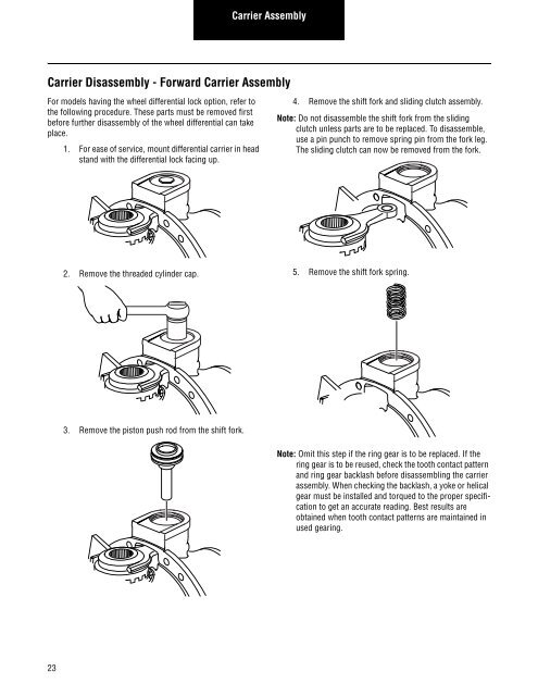
Carrier Disassembly - Forward Carrier Assembly<br />
For models having the wheel differential lock option, refer to<br />
the following procedure. These parts must be removed first<br />
before further disassembly of the wheel differential can take<br />
place.<br />
1. For ease of service, mount differential carrier in head<br />
stand with the differential lock facing up.<br />
2. Remove the threaded cylinder cap.<br />
3. Remove the piston push rod from the shift fork.<br />
4. Remove the shift fork and sliding clutch assembly.<br />
Note: Do not disassemble the shift fork from the sliding<br />
clutch unless parts are to be replaced. To disassemble,<br />
use a pin punch to remove spring pin from the fork leg.<br />
The sliding clutch can now be removed from the fork.<br />
5. Remove the shift fork spring.<br />
Note: Omit this step if the ring gear is to be replaced. If the<br />
ring gear is to be reused, check the tooth contact pattern<br />
and ring gear backlash before disassembling the carrier<br />
assembly. When checking the backlash, a yoke or helical<br />
gear must be installed and torqued to the proper specification<br />
to get an accurate reading. Best results are<br />
obtained when tooth contact patterns are maintained in<br />
used gearing.