Spicer Tandem Drive Axles Service Manual
Spicer Tandem Drive Axles Service Manual
Spicer Tandem Drive Axles Service Manual

Create successful ePaper yourself
Turn your PDF publications into a flip-book with our unique Google optimized e-Paper software.
<strong>Spicer</strong> ®<br />
<strong>Tandem</strong> <strong>Drive</strong> <strong>Axles</strong><br />
<strong>Service</strong> <strong>Manual</strong><br />
<strong>Spicer</strong><br />
AXSM-0057<br />
January 2009<br />
® <strong>Tandem</strong> <strong>Drive</strong> <strong>Axles</strong><br />
D170 Series<br />
D190 Series<br />
D590 Series
This page intentionally left blank.
General Inspection<br />
General Information<br />
The description and specifications contained in this service publication are current at the time of printing.<br />
Dana Corporation reserves the right to discontinue or to modify its models and/or procedures and to change specifications at any<br />
time without notice.<br />
Any reference to brand names in this publication is made simply as an example of the types of tools and materials recommended<br />
for use and should not be considered an endorsement. Equivalents, if available, may be used.<br />
Important Notice<br />
This symbol is used throughout this<br />
manual to call attention to procedures<br />
where carelessness or failure to follow<br />
specific instructions may result in<br />
personal injury and/or component<br />
damage.<br />
Departure from the instructions, choice<br />
of tools, materials and recommended<br />
parts mentioned in this publication<br />
may jeopardize the personal safety<br />
of the service technician or vehicle<br />
operator.<br />
Always use genuine Dana replacement parts.<br />
WARNING: Failure to follow indicated<br />
procedures creates a high risk of personal<br />
injury to the servicing technician.<br />
CAUTION: Failure to follow indicated<br />
procedures may cause component<br />
damage or malfunction.<br />
IMPORTANT: Highly recommended<br />
procedures for proper service of this unit.<br />
Note: Additional service information not<br />
covered in the service procedures.<br />
Tip: Helpful removal and installation<br />
procedures to aid in the service of this unit.<br />
i<br />
General Information
Table of Contents<br />
ii<br />
Wheel<br />
Differential<br />
Assembly<br />
page 35<br />
Wheel<br />
End Seal<br />
page 59<br />
Carrier<br />
Assembly<br />
page 23<br />
General Information<br />
<strong>Drive</strong><br />
Pinion<br />
page 25<br />
Wheel<br />
Differential<br />
Lock<br />
page 48<br />
Output Shaft<br />
Assembly &<br />
Rear Cover<br />
page 49<br />
Power<br />
Divider<br />
page 12<br />
Housing<br />
Breather<br />
page 58<br />
Lubrication<br />
page 66<br />
Seals<br />
page 55<br />
Inter-Axle<br />
Lockout<br />
page 11<br />
Differential<br />
Carrier<br />
Assembly<br />
page 8
Introduction ........................................................1<br />
Model Identification ............................................2<br />
Parts Identification ...................................................... 2<br />
Failure Analysis ...................................................4<br />
Prepare the Parts for Inspection ................................. 5<br />
Inspection ...........................................................6<br />
Endplay Procedure ...................................................... 7<br />
Check Input Shaft Endplay (Forward Axle) .................. 7<br />
Check Output Shaft Endplay (Forward Axle)................ 7<br />
Differential Carrier Assembly - Parts ...................8<br />
Remove Differential Carrier -<br />
(Forward and Rear) .............................................9<br />
Install Differential Carrier (Forward and Rear) ...10<br />
IAD Differential Lock Disassembly ....................11<br />
Inter-Axle Lockout..................................................... 11<br />
Power Divider - Parts Exploded View ................12<br />
Power Divider Disassembly - Forward<br />
Carrier Assembly ...............................................13<br />
Pump Disassembly ...........................................15<br />
Lube Manifold Disassembly ...................................... 16<br />
Manifold Assembly ...........................................17<br />
Pump Assembly ................................................18<br />
Power Divider Assembly ...................................19<br />
Carrier Disassembly - Forward Carrier<br />
Assembly ..........................................................23<br />
Pinion Removal .................................................25<br />
Forward Axle Pinion Assembly - Parts<br />
Exploded View ..................................................27<br />
Rear Axle Pinion Assembly - Parts Exploded View.... 27<br />
<strong>Drive</strong> Pinion Overhaul and Assembly -<br />
Forward and Rear Carrier Assembly ..................28<br />
Wheel Differential - Parts Exploded View ..........35<br />
Wheel Differential Disassembly .........................36<br />
Wheel Differential Assembly .............................38<br />
Wheel Differential Assembly ............................40<br />
Adjust Tooth Contact Position ..........................45<br />
Wheel Differential Lock -<br />
Parts Exploded View .........................................47<br />
Install and Adjust Wheel Differential Lock .........48<br />
Housing and Output Shaft Assembly -<br />
Parts Exploded View .........................................49<br />
Table of Contents<br />
Remove Output Shaft Assembly .......................50<br />
Overhaul and Assemble Output Shaft Assembly 52<br />
Measure ............................................................54<br />
Replace Seal .....................................................55<br />
Guidelines for Reusing Yoke...................................... 56<br />
<strong>Service</strong> Kit .........................................................57<br />
Housing Breather ..............................................58<br />
Wheel End Seal - Parts Exploded View .............59<br />
Remove and Overhaul Wheel End Seal .............60<br />
Adjust Wheel Bearing ........................................61<br />
Verify Wheel Endplay Procedure .......................63<br />
Readjust Wheel Endplay Procedure ........................... 63<br />
Lubricate Wheel End .........................................64<br />
Wheel Ends with an Oil Fill Hole ................................ 64<br />
Wheel Ends Without Oil Fill Hole ............................... 65<br />
General Lubrication Information .......................66<br />
Approved Lubricants ................................................. 66<br />
Recommendations for Viscosity/Ambient<br />
Temperature .............................................................. 66<br />
Lube Change Intervals ......................................67<br />
Change Lube .....................................................68<br />
Drain.......................................................................... 68<br />
Fill.............................................................................. 68<br />
Standpipes ........................................................69<br />
Final Check ................................................................ 70<br />
Proper Vehicle Towing ......................................71<br />
Power Divider Operation (Power Flow<br />
and Torque Distribution) ...................................72<br />
Operate Wheel Differential Assembly ................74<br />
Control Systems for Differential Lock ........................ 74<br />
Wheel Differential Lock .....................................76<br />
Power Divider - Parts Exploded View ................78<br />
Forward Axle Pinion Assembly -<br />
Parts Exploded View .........................................79<br />
Rear Axle Pinion Assembly - Parts<br />
Exploded View ..................................................80<br />
Wheel Differential Lock - Parts<br />
Exploded View ..................................................81<br />
Housing and Output Shaft Assembly -<br />
Parts Exploded View .........................................82<br />
Fastener Torque Specifications .........................83<br />
Table of Contents
Introduction<br />
Dana Corporation, Commercial Vehicle Systems Division, presents<br />
this publication to aid in maintenance and overhaul of<br />
Dana tandem drive axles.<br />
Instructions contained cover the models listed. Their design is<br />
similar, with primarily differences in load capacity. Capacity<br />
variations are achieved by combining basic differential carrier<br />
assemblies with different axle housings, axle shafts and wheel<br />
equipment.<br />
The suffix letter “P” in the model number indicates optional<br />
lube pump. The pump is designed to provide additional lubrication<br />
to the inter-axle differential and related parts.<br />
1<br />
Model Listing<br />
D - Dual <strong>Drive</strong> Forward Axle<br />
with Inter-Axle Differential<br />
G - Single Rear Axle (Global)<br />
R - Dual <strong>Drive</strong> Rear Axle<br />
S - Single Rear Axle (N.A.)<br />
GAW Rating<br />
x 1000 lbs. (N. America) "-"<br />
x 1 Tn. (Europe) "."<br />
General Information<br />
Model Information<br />
The following models are included in this publication:<br />
Heavy <strong>Tandem</strong>s<br />
D 46-1 7 0 D<br />
Gear Type<br />
1 - Standard Single Reduction<br />
2 - Dual Range<br />
3 - Planetary Double Reduction<br />
4 - Open<br />
5 - Helical Reduction<br />
D40-170 D46-590HP<br />
D40-170(P) D50-170<br />
D40-170D(P) D52-190P<br />
D46-170 D52-190DP<br />
D46-170(P) D52-590P<br />
D46-170D(P) D60-190P<br />
D46-170H D60-590P<br />
D46-170H(P)<br />
D46-170DH(P)<br />
D70-190P<br />
Design Level<br />
Head Assembly Series<br />
Options<br />
C - Controlled Traction<br />
D - Differential Lock<br />
E - High Entry Single<br />
H - Heavy Wall<br />
I - Integral Brake<br />
L - Limited-Slip<br />
P - Lube Pump<br />
R - Retarder Ready<br />
W - Wide-Track
Model Identification<br />
<strong>Drive</strong> Axle<br />
1 - Country or origin<br />
2 - Axle model identification<br />
3 - Specification number assigned to the axle built by Dana.<br />
Identifies all component parts of the axle including special<br />
OEM requirements such as yokes or flanges.<br />
Parts Identification<br />
General Information<br />
Axle Housing Axle Shaft<br />
1 - ID Tag<br />
<strong>Spicer</strong> ®<br />
PT. NO.<br />
HSG. CAP. LBS.<br />
HSG. I.D. NO.<br />
HOUSING MADE IN<br />
1<br />
4 - OEM part number assigned to the axle build<br />
5 - Carrier assembly serial number assigned by the<br />
manufacturing plant<br />
6 - Axle gear ratio<br />
7 - Carrier assembly production or service part number<br />
2 - Axle shaft part number<br />
2<br />
2<br />
General Information
Ring Gear and Pinion<br />
Note: Ring gear and drive pinion are matched parts and must<br />
be replaced in sets.<br />
1 - Part number<br />
2 - Number of ring gear teeth<br />
3 - Manufacturing numbers<br />
4 - Matching gear set number<br />
5 - Number of pinion teeth<br />
6 - Date code<br />
7 - Indicates genuine <strong>Spicer</strong> parts<br />
8 - Heat code<br />
3<br />
85405<br />
EATON<br />
6-39<br />
127381<br />
JD77<br />
86<br />
1<br />
7<br />
SPICER<br />
General Information<br />
7<br />
5<br />
SPICER<br />
127428<br />
1<br />
41-8<br />
8<br />
8-41<br />
17 G<br />
OF<br />
NL217<br />
2<br />
127 0H<br />
4<br />
L7038<br />
8<br />
6<br />
3<br />
3<br />
6<br />
G<br />
L7038<br />
4
Failure Analysis<br />
Failure analysis is the process of determining the original<br />
cause of a component failure in order to keep it from<br />
happening again. Too often, when a failed component is<br />
replaced without determining its cause, there will be a recurring<br />
failure. If a carrier housing is opened, revealing a ring<br />
gear with a broken tooth, it is not enough to settle on the broken<br />
tooth as the cause of the carrier failure. Other parts of the<br />
carrier must be examined. For a thorough understanding of<br />
the failure and possible insight into related problems, the<br />
technician needs to observe the overall condition of the vehicle.<br />
No one benefits when a failed component goes on the junk<br />
pile with the cause unknown. Nothing is more disturbing to a<br />
customer than a repeat failure. Systematically analyzing a failure<br />
to prevent a repeat occurrence assures quality service by<br />
avoiding unnecessary downtime and further expense to the<br />
customer.<br />
The true cause of a failure can be better determined by<br />
knowing what to look for, determining how a piece of the<br />
equipment was running, and learning about previous problems.<br />
In the case of a rebuilt rear axle, mismatched gears may<br />
have been installed.<br />
The more successful shops prevent repeat equipment failures<br />
by developing good failure analysis practices. Knowing how<br />
to diagnose the cause of a premature failure is one of the<br />
prerequisites of a good heavy-equipment technician.<br />
How to Diagnose a Failure<br />
The following five steps are an effective approach to good<br />
failure diagnostics.<br />
1. Document the problem.<br />
2. Make a preliminary investigation.<br />
3. Prepare the parts for inspection.<br />
4. Find the cause of the failure.<br />
5. Correct the cause of the problem.<br />
Inspection<br />
Document the Problem<br />
Here are some guidelines for starting to learn about a failure.<br />
Talk to the operator of the truck.<br />
Look at the service records.<br />
Find out when the truck was last serviced.<br />
Ask the following questions:<br />
In what type of service is the truck being used?<br />
Has this particular failure occurred before?<br />
How was the truck working prior to the failure?<br />
You need to be a good listener. Sometimes, insignificant or<br />
unrelated symptoms can point to the cause of the failure.<br />
Ask the following questions:<br />
Was the vehicle operating at normal temperatures?<br />
Were the gauges showing normal ranges of operation?<br />
Was there any unusual noise or vibration?<br />
After listening, review the previous repair and maintenance<br />
records. If there is more than one driver, talk to all of them<br />
and compare their observations for consistency with the<br />
service and maintenance records. Verify the chassis Vehicle<br />
Identification Number (VIN) number from the vehicle identification<br />
plate, as well as the mileage and hours on the vehicle.<br />
4<br />
Inspection
Make a Preliminary Investigation<br />
These steps consist of external inspections and observations<br />
that will be valuable when combined with the results of the<br />
parts examination.<br />
5<br />
Look for leaks, cracks or other damage that can<br />
point to the cause of the failure.<br />
Make note of obvious leaks around plugs and seals.<br />
A missing fill or drain plug would be an obvious<br />
cause for concern.<br />
Look for cracks in the carrier housing (harder to see,<br />
but sometimes visible).<br />
Does the general mechanical condition of the vehicle<br />
indicate proper maintenance or are there signs of<br />
neglect?<br />
Are the tires in good condition and do the sizes<br />
match?<br />
If equipped with a torque-limiting device, is it working<br />
properly?<br />
During the preliminary investigation, write down anything<br />
out of the ordinary for later reference. Items that appear<br />
insignificant now may take on more importance when the<br />
subassemblies are torn down.<br />
Prepare the Parts for Inspection<br />
After the preliminary investigation, locate the failure and prepare<br />
the part for examination. In carrier failure analysis, it may<br />
be necessary to disassemble the unit.<br />
When disassembling subassemblies and parts, do<br />
not clean the parts immediately since cleaning may<br />
destroy some of the evidence.<br />
When tearing down the drive axle, do it in the recommended<br />
manner. Minimize any further damage to the<br />
unit.<br />
Ask more questions when examining the interior of<br />
the carrier. Does the lubricant meet the manufacturer<br />
specifications regarding quality, quantity and viscosity?<br />
As soon as you have located the failed part, take<br />
time to analyze the data.<br />
Inspection<br />
Find the Cause of the Failure<br />
Here begins the real challenge to determine the exact cause of<br />
the failure. Keep in mind that there is no benefit to replacing a<br />
failed part without determining the cause of the failure. For<br />
example, after examining a failed part and finding that the failure<br />
is caused by a lack of lubrication, you must determine if<br />
there was an external leak. Obviously, if there is an external<br />
leak, just replacing the failed gear is not going to correct the<br />
situation.<br />
Another important consideration is to determine the specific<br />
type of failure which can be a valuable indicator for the cause<br />
of failure. The following pages show different types of failures<br />
and possible causes. Use this as a guide in determining types<br />
of failures and to correct problems.<br />
Correct the Cause of the Problem<br />
Once the cause of the problem has been determined, refer to<br />
the appropriate service manual to perform the repairs.
Inspection<br />
Clean<br />
1. Wash steel parts with ground or polished surfaces<br />
in solvent. There are many suitable commercial<br />
solvents available. Kerosene and diesel fuel are<br />
acceptable.<br />
WARNING<br />
Gasoline is not an acceptable solvent because of its<br />
extreme combustibility. It is unsafe in the workshop environment.<br />
2. Wash castings or other rough parts in solvent or<br />
clean in hot solution tanks using mild alkali solutions.<br />
Note: If a hot solution tank is used, make sure parts are<br />
heated thoroughly before rinsing.<br />
3. Rinse thoroughly to remove all traces of the cleaning<br />
solution.<br />
4. Dry parts immediately with clean rags.<br />
5. Oil parts.<br />
If parts are to be reused immediately: Lightly oil.<br />
If parts are to be stored: Coat with oil, wrap in<br />
corrosion resistant paper and store in a clean,<br />
dry place.<br />
Inspect Axle Housing<br />
Axle housing inspection and repairs are limited to the<br />
following checks or repairs.<br />
Visually inspect axle housing for cracks, nicks, and<br />
burrs on machined surfaces.<br />
Check carrier bolt holes and studs for foreign<br />
material.<br />
Replace damaged fasteners. Look for loose studs or<br />
cross threaded holes.<br />
CAUTION<br />
Any damage which affects the alignment or structural integrity<br />
of the housing requires housing replacement. Do not<br />
repair by bending or straightening. This process can affect<br />
the material's properties and cause it to fail completely<br />
under load.<br />
Check all seals and gaskets.<br />
Inspection<br />
Note: Replace conventional gaskets with silicone rubber<br />
gasket compound (included in many repair kits). The<br />
compound provides a more effective seal against lube<br />
seepage and is easier to remove from mating surfaces<br />
when replacing parts.<br />
2<br />
1 - Axle housing<br />
2 - Machined surface<br />
Inspect Components<br />
Inspect all steel parts for:<br />
Notches, visible steps or grooves created by wear.<br />
Pitting or cracking along gear contact lines.<br />
Scuffing, deformation, or discolorations. These are<br />
signs of excessive heat in the axle and are usually<br />
related to low lubrication levels or improper lubrication<br />
practices.<br />
In addition, inspect the following for damage:<br />
Differential gearing.<br />
Bearings for loose fit on drive pinion, pilot bearing,<br />
and differential bearings.<br />
All fasteners for rounded heads, bends, cracks, or<br />
damaged threads.<br />
Inspect machined surfaces of cast or malleable<br />
parts. They must be free of nicks, burrs, cracks,<br />
scoring, and wear.<br />
Look for elongation of drilled holes, wear on surfaces<br />
machined for bearing fits and nicks or burrs in<br />
mating surfaces.<br />
Inspect Primary Gearing<br />
Before reusing a primary gear set, inspect teeth for signs of<br />
excessive wear. Check tooth contact pattern for evidence of<br />
incorrect adjustment.<br />
1<br />
6<br />
Inspection
Endplay Procedure<br />
Check Input Shaft Endplay (Forward Axle)<br />
Note: Before disassembling the power divider, measure and<br />
record input shaft endplay.<br />
1. Position dial indicator at yoke end of input shaft.<br />
2. Push in on input shaft and zero the dial indicator.<br />
3. Using a pry bar, move input shaft axially and measure/record<br />
endplay.<br />
Adjustment<br />
Correct endplay for a new assembly is 0.001" to 0.005". See<br />
the "Input Shaft Endplay" procedure in the "Power Divider<br />
Assembly" section for proper endplay adjustment procedure.<br />
7<br />
Inspection<br />
Check Output Shaft Endplay (Forward Axle)<br />
1. Position dial indicator at yoke end of output shaft.<br />
2. Push in on output shaft and zero the dial indicator.<br />
3. Using a pry bar, move output shaft axially and measure/record<br />
endplay.<br />
Adjustment<br />
Correct endplay for a new assembly is 0.001" to 0.045". The<br />
maximum endplay for a used assembly is no more than<br />
0.045". If endplay is incorrect, contact Dana.
Differential Carrier Assembly - Parts<br />
1 - Carrier fasteners<br />
2 - Carrier assembly<br />
3 - Forward axle assembly<br />
4 - Rear axle assembly<br />
4<br />
3<br />
Differential Carrier Assembly<br />
1<br />
1<br />
2<br />
2<br />
8<br />
Differential Carrier<br />
Assembly
9<br />
Differential Carrier Assembly<br />
Remove Differential Carrier - (Forward and Rear)<br />
Note: The removal of the forward carrier does not require disconnecting<br />
of the inter-axle driveline and removal of the<br />
output shaft yoke assembly as most other Dana tandems<br />
require.<br />
Standard Differentials<br />
1. Block the vehicle.<br />
2. Drain axle lubricant.<br />
3. Rear Only: Disconnect inter-axle driveline.<br />
4. Front Only: Disconnect main driveline.<br />
5. Front Only: Disconnect differential lockout air line.<br />
6. Disconnect lead wires to the selector switch and air<br />
line at shift cylinder.<br />
7. Remove axle shafts.<br />
WARNING<br />
Do not lie under carrier after fasteners are removed. Use<br />
transmission jack to support differential carrier assembly<br />
prior to loosening fasteners.<br />
8. To remove axle shaft, remove axle stud nuts.<br />
(If used, remove lock washers and taper dowels.)<br />
9. Remove axle shafts.<br />
Note: All models in this publication use axle shafts with<br />
unequal lengths. Axle shafts may also be location specific<br />
with various wheel equipment. Do not misplace axle<br />
shafts from their intended location. Identify left and right<br />
shafts for reference during reassembly.<br />
TIP: If necessary, loosen dowels by holding a brass<br />
drift in the center of the shaft head and striking drift<br />
with a sharp blow with a hammer.<br />
CAUTION<br />
Do not strike the shaft head with a steel hammer. Do not<br />
use chisels or wedges to loosen shaft or dowels.<br />
10. Remove carrier capscrews, nuts, and lock washers.<br />
11. Remove differential carrier assembly.
Differential Carrier Assembly<br />
Install Differential Carrier (Forward and Rear)<br />
Before installing carrier assembly, inspect and thoroughly<br />
clean interior of axle housing using an appropriate solvent<br />
and clean rag.<br />
1. Apply Dana approved RTV compound on axle<br />
housing mating surface as shown in the illustration.<br />
Completely remove all old gasket material prior to<br />
applying new material. Compound will set in<br />
5 minutes. Install carrier before compound sets or<br />
reapply.<br />
1<br />
IMPORTANT<br />
1 - Apply silicone gasket in this pattern<br />
Tip: To assist in installing complete differential carrier<br />
use two pieces of threaded rod (M16 X 1.5)<br />
threaded into carrier capscrew holes. Rod should be<br />
approximately 6" long. Use these to pilot the carrier<br />
into the housing.<br />
2. Install carrier to housing, lock washers, capscrews<br />
and nuts. Torque to proper specification. Torque to<br />
250–290 lbs. ft. (339–393 N m).<br />
3. Install axle shafts and axle stud nuts. (If used, also<br />
install lock washers and tapered dowels.)<br />
4. Add axle lubricant. Fill to bottom of filler hole.<br />
5. Rear Only: Connect inter-axle driveline, making sure<br />
all yokes are in phase. Lubricate u-joints.<br />
6. Front Only: Connect main driveline, making sure all<br />
yokes are in phase. Lubricate u-joints.<br />
7. Front Only: Connect differential lockout air line.<br />
10<br />
Differential Carrier<br />
Assembly
IAD Differential Lock Disassembly<br />
Inter-Axle Lockout<br />
Integral Shift Cylinder with Welded Push Rod Assembly<br />
11<br />
5<br />
4<br />
2<br />
3<br />
1 - Compression spring<br />
2 - Shift fork assembly<br />
3 - Piston<br />
4 - O-ring<br />
5 - Piston cover<br />
1<br />
Inter-Axle Lockout<br />
Disassembly<br />
1. With the axle installed in vehicle, place differential<br />
lock selector valve in the disengaged or unlocked<br />
position.<br />
2. Disconnect the differential lockout air line.<br />
3. Remove the piston cover.<br />
4. Remove the piston and o-ring assembly with pliers.<br />
Note: In order to remove the shift fork and push rod parts,<br />
first remove the power divider cover. See the Power<br />
Divider section.<br />
Assembly<br />
1. Assemble the o-ring onto the piston. Apply silicone<br />
grease to the o-ring.<br />
2. Gently push the piston o-ring assembly into the lockout<br />
cylinder bore. Make sure the piston assembly is<br />
pushed in all the way.<br />
3. Install the piston cover. Tighten by hand and then<br />
torque from 50-75 lbs. ft. (68-102 N m).<br />
4. Connect the differential lock air line.<br />
5. Cycle the lockout to make sure there are no leaks<br />
and the system is operating properly.
Power Divider - Parts Exploded View<br />
19<br />
20<br />
21<br />
23<br />
24<br />
1 - Output shaft nut<br />
2 - Output yoke<br />
3 - Output seal<br />
4 - Output shaft bearing snap ring<br />
5 - Outer bearing cup<br />
6 - Outer bearing cone<br />
7 - Inner bearing cone<br />
8 - Inner bearing cup<br />
9 - Output shaft<br />
10 - Seal manifold<br />
11 - Clamp<br />
12 - Seal manifold feed tube<br />
13 - Sump screen<br />
14 - Output side gear bearing cup<br />
15 - Output side gear bearing cone<br />
1<br />
22<br />
25<br />
2<br />
3<br />
26<br />
4<br />
27<br />
Power Divider<br />
5<br />
28<br />
43 42<br />
16 - Pin<br />
17 - Output side gear<br />
18 - Pump<br />
19 - Inter-axle differential<br />
20 - Helical side gear<br />
21 - Thrust washer<br />
22 - Lockout sliding clutch<br />
23 - Shift fork spring<br />
24 - Shift fork assembly<br />
25 - V-ring<br />
26 - Input shaft<br />
27 - Input shaft<br />
28 - Input shaft bearing cone<br />
29 - Carrier housing<br />
30 - Locking capscrew<br />
6<br />
41<br />
29<br />
7<br />
8<br />
40<br />
30<br />
31<br />
9<br />
37 38 39<br />
32<br />
11<br />
12<br />
33<br />
34<br />
10<br />
11<br />
13<br />
35<br />
High Entry Input<br />
Shaft Assembly<br />
14<br />
36<br />
15<br />
44<br />
16<br />
17<br />
31 - Input cover<br />
32 - Input cover capscrew<br />
33 - Bearing cup and cage<br />
34 - Input seal<br />
35 - Input yoke<br />
36 - Input nut<br />
37 - Piston<br />
38 - O-ring<br />
39 - Piston cover<br />
40 - Pinion cover<br />
41 - Input cover capscrew<br />
42 - Input cover<br />
43 - Carrier housing<br />
18<br />
12<br />
Power Divider
13<br />
Power Divider<br />
Power Divider Disassembly - Forward Carrier Assembly<br />
Use these instructions with the carrier assembly in or out of<br />
the vehicle.<br />
1. Disconnect the main driveline.<br />
2. Disconnect the lockout airline.<br />
3. Drain the axle lubricant into a clean oil pan.<br />
4. Remove the input yoke nut and yoke.<br />
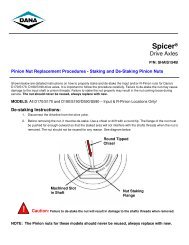
5. To de-stake the nut, use a chisel or drift with a round<br />
tip. The flange of the nut must be pushed far enough<br />
outward so that the staked area will not interfere with<br />
the input shaft threads when the nut is removed. See<br />
diagrams below.<br />
Failure to de-stake the pinion nut will result in damage to<br />
the drive pinion threads when removed. The pinion nut<br />
should never be reused, always replace with new.<br />
2<br />
CAUTION<br />
1 - Round Tipped Chisel<br />
2 - Machined Slot In Pinion<br />
3 - Nuts Staking Flange<br />
6. Remove the input seal.<br />
Note: Do not reuse the seals after disassembly.<br />
7. Remove the power divider cover assembly. Use the<br />
tabs provided to free the cover from the carrier<br />
assembly.<br />
1<br />
3<br />
CAUTION<br />
During removal of the power divider cover, the inter-axle<br />
differential (IAD), input shaft assembly or IAD shift system<br />
may fall from the carrier if not careful. Use caution to prevent<br />
injury or damage.<br />
8. For High Entry Applications Only:<br />
Remove the input shaft and gear assembly. Proceed<br />
to step 13.<br />
9. Remove the input shaft, sliding clutch, shift fork and<br />
spring as an assembly.
10. Remove the thrust washer and helical side gear.<br />
11. Remove the inter-axle differential assembly.<br />
12. Remove the output side gear and pump assembly.<br />
13. To replace the input bearing cup, back off the<br />
bearing cage locking fastener or jam nut and stud.<br />
Power Divider<br />
14. Input cage is threaded into the PDU cover, use the<br />
proper tool to remove the cage from the cover.<br />
15. Use a suitable bearing puller to replace the input<br />
bearing cup.<br />
Note: In August of 2006 the piloted input adjuster design was<br />
implemented. The lockin and fastener was replaced with<br />
a 12mm stud and jam nut. It is not recommended that<br />
the piloted designed adjuster and cover be mixed with<br />
the non-piloted design.<br />
Cover Pilot<br />
Adjuster Pilot<br />
14<br />
Power Divider
Pump Disassembly<br />
For output side gear and/or pump replacement, follow the<br />
procedure below.<br />
15<br />
1. Remove the output side gear bearing cone, if<br />
required.<br />
1 - Press<br />
2 - Press Tool<br />
2. Remove pump locking dowel pin from the hole in the<br />
output side gear hub.<br />
1<br />
2<br />
Power Divider<br />
3. Remove pump from the output side gear.<br />
4. Remove the output side gear bearing cup from the<br />
carrier with the proper bearing puller tool.
Lube Manifold Disassembly<br />
1. Disconnect the hose from the lube manifold.<br />
2. Remove the manifold assembly by prying it out<br />
around the inner diameter.<br />
IMPORTANT<br />
Once removed, the seal manifold assembly cannot be<br />
reused. This component should always be replaced with<br />
new. Use the same removal procedure for the output side<br />
gear seal removal on the non-pump models.<br />
Note: Seals are not sold separately from the manifold.<br />
1 - Barbed Nipple<br />
1<br />
Power Divider<br />
16<br />
Power Divider
Manifold Assembly<br />
17<br />
1. Install the manifold assembly into the output side<br />
gear bore in the carrier. Make sure the barbed nipple<br />
is lined up with the opening in the carrier casting.<br />
1 - Barbed Nipple<br />
2. Install the hose clamp on the hose, push the hose<br />
onto the barbed fitting and slide the clamp over the<br />
barbed nipple.<br />
3. Route the suction end of the hose through the holes<br />
in the carrier casting to the bottom of the carrier.<br />
4. Fully press the manifold assembly into position.<br />
Note: Use care when pressing the manifold assembly to avoid<br />
damaging the seals and barbed nipple. Do not overpress<br />
plastic.<br />
1<br />
Power Divider<br />
Note: For non-pump manifold installation, it is important to<br />
line up the oil inlet path hole in the manifold with the oil<br />
path opening in the carrier manifold casting.<br />
1 - Manifold Oil Inlet Hole<br />
5. Attach the suction screen to the end of the hose.<br />
If the unit does not have a pump, go to the Power Divider<br />
Assembly section.<br />
If the unit contains a pump, go to the Pump Assembly section.<br />
1
Pump Assembly<br />
Use these instructions with the carrier assembly in or out of<br />
the vehicle.<br />
If the unit does not have a pump, go to the Power Divider<br />
Assembly section.<br />
Note: Keep work area clean. Dirt is an abrasive and will cause<br />
premature wear of the otherwise serviceable parts.<br />
Note: For non-pump models, see page 17 for output side gear<br />
seal manifold installation.<br />
Note: Only service the power divider if the differential carrier<br />
is secured in a stand or while the axle is still attached to<br />
the housing.<br />
CAUTION<br />
During installation of power divider cover, the inter-axle<br />
differential (IAD), input shaft assembly or IAD shift system<br />
parts may fall from the carrier if not careful. Use caution to<br />
prevent injury or damage.<br />
1. Install the pump into the output side gear so that the<br />
pump shaft is facing toward the teeth end of the side<br />
gear.<br />
Power Divider<br />
2. Install the pump locking dowel pin into the hole in<br />
the output side gear hub. Make sure the pin is lined<br />
up with the machined slot in the pump body.<br />
1 - Machined Slot<br />
2 - Pin<br />
1 2<br />
18<br />
Power Divider
Power Divider Assembly<br />
19<br />
1. Install output side gear bearing cone and press until<br />
fully seated. Use proper press tools.<br />
1 - Press<br />
2 - Press Tool<br />
2. Fully press the output side gear bearing cup into the<br />
carrier seat.<br />
When inserting the input shaft assembly through the IAD<br />
components, turn the shaft as necessary to align the slot of<br />
the input shaft with the pump drive shaft. The keyway on the<br />
threaded end of the input shaft is aligned with the pump<br />
driver slot. This can be used as a visual aid during assembly.<br />
3. Install the output side gear. Apply a thin layer of oil to<br />
the output side gear boss before installing into the<br />
seal.<br />
Note: For non-pump models, fill bore of output side gear<br />
models with synthetic grease.<br />
4. Install the inter-axle differential.<br />
1<br />
IMPORTANT<br />
2<br />
Power Divider<br />
Note: Install in the same direction as removed.<br />
5. Install the helical side gear so that the clutch teeth<br />
are facing upward in the carrier.<br />
6. Install helical side gear thrust washer.
Helical Gear Bushing Replacement:<br />
a. If bushing removal is needed, the bushings<br />
must exit from the thrust side of the helical side<br />
gear.<br />
1<br />
1 - Tap out bushings<br />
b. Install bushings in helical side gear. Bushing<br />
must be installed from the thrust side of the<br />
helical side gear. See illustration for installation<br />
depth.<br />
1<br />
2<br />
3<br />
4<br />
1 - Press<br />
2 - Sleeve<br />
3 - 1st bushing (press to shoulder)<br />
4 - Shoulder<br />
5 - Sleeve<br />
6 - 2nd bushing (recess 1.25 to 1.75 mm)<br />
7. Install the helical side gear thrust washer.<br />
8. Install the v-ring seal to the sliding clutch.<br />
1<br />
5<br />
6<br />
1.25 to 1.75 mm<br />
Power Divider<br />
9. Install the sliding clutch so that the teeth are facing<br />
up.<br />
10. If removed, press the new input bearing cone in<br />
place until seated using the proper press sleeve or<br />
bearing installer.<br />
1 - Press<br />
2 - Press Tool<br />
3 - Bearing<br />
4 - Input shaft<br />
11. For High Entry Applications Only:<br />
Install shaft/gear assembly. Proceed to step 13.<br />
20<br />
Power Divider
21<br />
12. Assemble the sliding clutch, shift fork and fork<br />
spring to the input shaft and install assembly into<br />
carrier. Make sure that the shift fork rod is piloted in<br />
the carrier bore.<br />
IMPORTANT<br />
Before installing input cover, inspect and thoroughly clean<br />
mating surfaces using an appropriate solvent and clean<br />
rag.<br />
Note: Completely remove all old gasket material prior to<br />
applying new Loctite.<br />
13. Apply a bead of Loctite 518 to the carrier surface as<br />
shown in the illustration.<br />
190 Cover<br />
170 Cover<br />
Power Divider<br />
14. Install input cover and capscrews. Torque to the<br />
proper specifications. See the Torque Chart on page<br />
D-1. Tighten fasteners in a criss cross pattern.<br />
15. Install input shaft bearing adjuster, adjust inward<br />
until snug against the bearing cone.<br />
Input Shaft Endplay<br />
16. Back off input bearing cage one notch and check<br />
endplay. Endplay should be between 0.001" to 0.005"<br />
(0.03 to 0.13 mm). Rotate cage in or out to get<br />
proper setting.<br />
1 - One Notch<br />
1
17. A. For axles built before August 2006. Line up cage<br />
slot with locking fastener. Turn in<br />
input cage locking fastener and torque to the proper<br />
specifications. See Torque Chart.<br />
B. For axles built after August 2006 using the<br />
piloted adjuster and cover. Torque locking stud to<br />
20 ft. lbs. then torque jam nut to 65 ft. lbs.<br />
18. Install input seal using proper installation tool.<br />
19. Install yoke and slinger assembly.<br />
Stud<br />
Jam Nut<br />
20. Install input shaft flanged nut and torque to the<br />
proper specifications. See Torque Chart.<br />
Note: A torque multiplier is recommended. If difficulty achieving<br />
correct torque, torque the nut with the truck wheels<br />
on the ground and with the axle shaft installed.<br />
Power Divider<br />
21. Verify that the endplay is between 0.001" to 0.005"<br />
(0.03 to 0.13 mm). If not, readjust until the proper<br />
specification is achieved.<br />
Note: High entry models should be set to an endplay of 0.001"<br />
to 0.005".<br />
22. Use a punch with a round tip to stake the pinion nuts<br />
flange into the machined slot in the pinion shaft. See<br />
diagram below.<br />
CAUTION<br />
The stake must be deep enough to enter the machined slot<br />
of the input shaft. See diagram below.<br />
1 - Round Tipped Chisel<br />
2 - Nuts Staking Flange<br />
3 - Machined Slot In Pinion<br />
Failure to stake the pinion nut properly may result in the nut<br />
coming loose during service. The pinion nut should never<br />
be reused, always replace with new.<br />
1<br />
WARNING<br />
3<br />
2<br />
22<br />
Power Divider
23<br />
Carrier Assembly<br />
Carrier Disassembly - Forward Carrier Assembly<br />
For models having the wheel differential lock option, refer to<br />
the following procedure. These parts must be removed first<br />
before further disassembly of the wheel differential can take<br />
place.<br />
1. For ease of service, mount differential carrier in head<br />
stand with the differential lock facing up.<br />
2. Remove the threaded cylinder cap.<br />
3. Remove the piston push rod from the shift fork.<br />
4. Remove the shift fork and sliding clutch assembly.<br />
Note: Do not disassemble the shift fork from the sliding<br />
clutch unless parts are to be replaced. To disassemble,<br />
use a pin punch to remove spring pin from the fork leg.<br />
The sliding clutch can now be removed from the fork.<br />
5. Remove the shift fork spring.<br />
Note: Omit this step if the ring gear is to be replaced. If the<br />
ring gear is to be reused, check the tooth contact pattern<br />
and ring gear backlash before disassembling the carrier<br />
assembly. When checking the backlash, a yoke or helical<br />
gear must be installed and torqued to the proper specification<br />
to get an accurate reading. Best results are<br />
obtained when tooth contact patterns are maintained in<br />
used gearing.
6. Mount the differential carrier in a head stand with the<br />
wheel differential facing upward.<br />
Note: For easier disassembly, loosen but do not remove the<br />
pinion nut.<br />
7. Remove the carrier differential bearing cap<br />
capscrews and bearing caps.<br />
Carrier Assembly<br />
8. Use Dana’s wheel diff. bearing adjustment tool (part<br />
number 513061) to back off the threaded cups and<br />
remove.<br />
1<br />
1 - Threaded bearing cup<br />
2 - Adjustment plate<br />
9. Use a chain hoist and the proper strap, lift the<br />
ring gear and wheel differential assembly from<br />
the carrier.<br />
2<br />
24<br />
Carrier Assembly
Pinion Removal<br />
25<br />
1. For D170 assembly, remove the pinion cover. Use a<br />
flat chisel to remove the cover from the carrier.<br />
2. If a pilot web is used, remove the web capscrews.<br />
1<br />
a. For D190 disassembly, install a M10 x 1.5<br />
bolt in the threaded jack holes found in-between<br />
the pilot web capscrews.<br />
1 - Threaded Jack Holes<br />
1<br />
<strong>Drive</strong> Pinion<br />
1<br />
b. For S190 disassembly, use the pry slots provided<br />
at each end of the pilot web.<br />
1 - Slots<br />
3. Before the pinion nut can be loosened, you must destake<br />
the nut from the slot of the pinion.<br />
4. To de-stake the nut, use a chisel or drift with a round<br />
tip. The flange of the nut must be pushed far enough<br />
outward so that the staked area will not interfere with<br />
the pinion threads when the nut is removed. See diagram<br />
on next page.<br />
1
Failure to de-stake the pinion nut will result in damage to<br />
the drive pinion threads when removed. The pinion nut<br />
should never be reused, always replace with new.<br />
2<br />
CAUTION<br />
1 - Round Tipped Chisel<br />
2 - Machined Slot In Pinion<br />
3 - Nuts Staking Flange<br />
5. Remove the pinion nut.<br />
6. Place carrier assembly into a press, place a 2" x 6" x<br />
6" wood block under the pinion. This will ensure that<br />
when the pinion is pressed free from the bearings<br />
the pinion will not be damaged.<br />
1<br />
1 - Carrier Assembly<br />
2 - Press<br />
3 - Pinion<br />
4 - Wood Block<br />
1<br />
2<br />
3<br />
4<br />
3<br />
<strong>Drive</strong> Pinion<br />
7. Use the proper pressing tool to press the end of the<br />
pinion until free from the pinion bearings.<br />
1 - Press<br />
8. Forward <strong>Axles</strong> Only: Remove the pinion spacer and<br />
the helical gear.<br />
IMPORTANT<br />
The bearing spacer will be reused or used as a starting<br />
point when resetting the pinion bearing preload. Do not discard<br />
this part.<br />
1<br />
26<br />
<strong>Drive</strong> Pinion
27<br />
<strong>Drive</strong> Pinion<br />
Forward Axle Pinion Assembly - Parts Exploded View<br />
1 - Pinion pilot bearing<br />
2 - Pinion<br />
3 - Pinion bearing cone - inner<br />
4 - Pinion bearing cup - inner<br />
5 - Pinion helical gear<br />
6 - Pinion bearing spacer<br />
Rear Axle Pinion Assembly - Parts Exploded View<br />
1 - Pinion pilot bearing<br />
2 - Pinion<br />
3 - Pinion bearing cone - inner<br />
4 - Pinion bearing cup - inner<br />
1<br />
1<br />
2<br />
2<br />
2<br />
5 - Pinion bearing spacer<br />
6 - Pinion bearing cup - outer<br />
7 - Pinion bearing cone - outer<br />
8 - Oil seal<br />
2<br />
3<br />
3<br />
4<br />
4<br />
5<br />
5<br />
6<br />
7<br />
7- Pinion bearing cup - outer<br />
8 - Pinion bearing cone - outer<br />
9 - Pinion nut<br />
6<br />
7<br />
8<br />
9 - Yoke<br />
10 - Pinion nut<br />
8<br />
9<br />
9<br />
10
<strong>Drive</strong> Pinion<br />
<strong>Drive</strong> Pinion Overhaul and Assembly - Forward and Rear Carrier Assembly<br />
The preload of the bearings on the drive pinion is adjusted by<br />
a spacer between the inner and outer bearing cones and the<br />
helical gear. The preload is adjusted by changing the thickness<br />
of the spacer. A thicker spacer will decrease the preload,<br />
a thinner spacer will increase the bearing preload.<br />
The following procedure covers both the forward and rear axle<br />
carrier overhaul and assembly.<br />
Note: See carrier disassembly for instructions on pinion and<br />
yoke removal.<br />
1. If the model of axle uses a pilot bearing, remove the<br />
bearing using a split-type puller. Use two procedure<br />
steps to remove each bearing.<br />
a. Mount the puller vertically to separate the<br />
bearing from the pinion. This action will force<br />
the puller halves behind the bearing race and<br />
start moving the bearing from the pinion.<br />
b. Mount the puller horizontally to press the<br />
bearing from the pinion.<br />
2. Remove the inner pinion bearing cone from the pinion<br />
using a split-type puller. Use two procedure<br />
steps to remove each bearing.<br />
1<br />
a. Mount the puller vertically to separate the<br />
bearing from the pinion. This action will force<br />
the puller halves behind the bearing race and<br />
start moving the bearing from the pinion.<br />
b. Mount the puller horizontally to press the<br />
bearing from the pinion.<br />
1 - Press<br />
28<br />
<strong>Drive</strong> Pinion
Use the correctly sized spacer. Do not use shim stock or<br />
grind spacers. These practices can lead to loss of bearing<br />
preload and gear or bearing failure.<br />
To prevent bearing damage, use suitable sleeve that only<br />
contacts the inner race of bearing cone.<br />
29<br />
IMPORTANT<br />
3. Use a press sleeve to install the inner bearing cone<br />
and pilot bearing, if used, onto the pinion. Apply<br />
pressure until the bottom of the cone touches the<br />
shoulder of the pinion. Apply lubricant to the cone of<br />
the bearing.<br />
EATON<br />
86<br />
85405<br />
JD77<br />
4. If removed, install the inner and outer bearing cups<br />
into the carrier.<br />
6-39<br />
L7038<br />
a. To install the inner bearing cup, place the carrier<br />
in a press with the bottom of the carrier facing<br />
up.<br />
b. Place the cup in the bore, use a sleeve or<br />
bearing driver tool to press the cup until it is<br />
fully seated. Use a feeler gage to make sure the<br />
cup is fully seated.<br />
<strong>Drive</strong> Pinion<br />
c. If replacement of the output shaft side gear<br />
bearing cup is necessary, use either of the following<br />
methods:<br />
Weld: Place a weld bead around the inside of<br />
the cup, when the weld cools the cup will fall<br />
out.<br />
Hammer: Use slipper to get under the cup and<br />
with a hammer and drift from the back side of<br />
carrier tap out bearing cup.<br />
d. To install the outer bearing cup, place the carrier<br />
in a press with the top of the carrier facing<br />
up.<br />
e. Place the cup in the bore, use a sleeve or<br />
bearing driver tool to press the cup until it is<br />
fully seated. Use a feeler gage to make sure the<br />
cup is fully seated.<br />
Note: If a press is not available, use a sleeve or bearing driver<br />
and a hammer to install the cups.
5. For Forward Carriers Only: Install the helical with<br />
the larger boss side facing down in the carrier. Align<br />
the helical gear between the inner and outer bearing<br />
cups.<br />
1 - Large - Long Boss<br />
6. Place the pinion on a 6 x 6 x 6 block of wood and<br />
lower the carrier over the pinion.<br />
1<br />
<strong>Drive</strong> Pinion<br />
7. To align the splines of the helical gear to the<br />
pinion, use a old pinion nut with a metal ring welded<br />
to the top, thread onto the pinion. Then lift the pinion<br />
while aligning the two splined surfaces.<br />
8. Install the pinion spacer.<br />
Note: If you are using the same drive pinion, use the same<br />
spacer that was originally installed in the assembly. If<br />
the drive pinion is to be replaced, the original spacer will<br />
be used as the starting point of adjustment.<br />
30<br />
<strong>Drive</strong> Pinion
31<br />
9. Install the outer bearing cone.<br />
10. Install a pinion nut finger tight. This will hold the pinion<br />
in place while it is positioned into the press.<br />
<strong>Drive</strong> Pinion<br />
11. Align a 6” x 6” x 6” wood block under the drive pinion,<br />
then lower the carrier and pinion assembly into<br />
a press so that it is supported by the block.<br />
12. Remove the pinion nut.<br />
13. Place a press sleeve over the top of the outer bearing<br />
cone. Use the press to apply 5 tons of force. It is<br />
important to rotate the carrier slightly to make sure<br />
that the rollers of the bearing are properly seated.
14. With 5 tons of force on the press, you should be able<br />
to feel a small amount of drag from the bearing as<br />
you rotate the carrier. If the carrier turns with no<br />
drag at all, the pinion spacer thickness should be<br />
decreased by using a thinner spacer. If the carrier is<br />
hard to turn, the spacer thickness must be<br />
increased.<br />
15. Remove the carrier from the press and reinstall the<br />
pinion nut.<br />
<strong>Drive</strong> Pinion<br />
16. Run the nut down with an impact gun. The pinion<br />
should still have the same slight drag that was<br />
obtained in the press.<br />
17. Secure the carrier in a head stand, rotate carrier so<br />
the pinion nut can be torqued.<br />
32<br />
<strong>Drive</strong> Pinion
33<br />
TIP: A torquing wedge can be made to hold the helical<br />
gear from turning while the nut is torqued.<br />
18. Install the wedge between the carrier wall and the<br />
teeth of the helical gear.<br />
1<br />
1 - Wedge<br />
19. Torque the nut to 800-1000 lbs. ft.<br />
(1084-1355 N m).<br />
TIP: If you are unable to torque the yoke nut correctly,<br />
try torquing the nut with the truck wheels on<br />
the ground and with the axle shafts installed.<br />
<strong>Drive</strong> Pinion<br />
20. Use an lbs. in. torque wrench and correct socket to<br />
check the rolling torque of the pinion. Read torque<br />
while rotating the assembly. Record the rotating<br />
torque, not the breakaway torque. Torque must be<br />
between 20 to 50 lbs. in. If the torque recorded is not<br />
within the specified torque, the pinion spacer must<br />
be changed. Repeat Steps 6-17.<br />
21. Once the proper rolling torque is achieved, use a<br />
punch with a round head to stake the nut collar into<br />
the slot in the pinion.<br />
Note: Always use a new nut and coat threads with Loctite 277<br />
if not pre-coated.
CAUTION<br />
The stake must be deep enough to enter the machined slot<br />
of the pinion. See diagram below.<br />
1 - Round Tipped Chisel<br />
2 - Nuts Staking Flange<br />
3 - Machined Slot In Pinion<br />
Failure to stake the pinion nut properly may result in the nut<br />
coming loose during service. The pinion nut should never<br />
be reused, always replace with new.<br />
22. For D170 assembly, install the pinion cover. Apply a<br />
bead of Loctite 518 sealant to the outer flange of the<br />
cover.<br />
23. Install the cover, making sure that the cover is parallel<br />
to the carrier opening.<br />
1<br />
WARNING<br />
3<br />
2<br />
<strong>Drive</strong> Pinion<br />
24. Use a dead blow mallet to seat the cover.<br />
25. If a pilot bearing web is used, lineup the web to<br />
the locating sleeves and tap in place with a rubber<br />
mallet.<br />
1<br />
1 - Locating Sleeves<br />
26. Install capscrews and torque to the proper specifications.<br />
See the Torque Chart.<br />
1<br />
34<br />
<strong>Drive</strong> Pinion
Wheel Differential - Parts Exploded View<br />
1 - Threaded bearing adj. - flange half<br />
2 - Bearing cone - flange half<br />
3 - Differential case - flange half<br />
4 - Ring gear<br />
5 - Ring gear bolt<br />
35<br />
12<br />
4<br />
11<br />
Wheel Differential<br />
9<br />
3<br />
6 - Side gear<br />
7 - Side pinion<br />
8 - Differential spider<br />
9 - Differential case - plain half<br />
6<br />
2<br />
8<br />
1<br />
5<br />
10<br />
7<br />
6<br />
10 - Differential case - plain half<br />
wheel diff. lock<br />
11 - Bearing cone - plain half<br />
12 - Threaded bearing adj. - plain half
Wheel Differential Disassembly<br />
During the following procedures, place the<br />
differential assembly on a malleable surface to prevent<br />
damage when removing components.<br />
1. Remove the differential case capscrews.<br />
2. Remove the flange half differential case and bearing<br />
assembly. Use a screwdriver at the spider arm<br />
machined slots of the case to loosen the flange from<br />
the ring gear.<br />
1<br />
1 - Spider Arm Slots<br />
IMPORTANT<br />
Wheel Differential<br />
3. Remove the side gears, side pinions and differential<br />
spider from the plain half case.<br />
4. Place a block under the plain half, use a rubber mallet<br />
to remove the ring gear.<br />
5. Remove the bearing cones from the case halves<br />
using suitable pullers.<br />
36<br />
Wheel Differential
37<br />
6. Remove the bearing cones from the plain and flange<br />
halves in two steps:<br />
a. Mount the puller vertically to split the bearing.<br />
This action will start the bearing moving off the<br />
differential case.<br />
b. Mount the puller horizontally to remove the<br />
cone.<br />
Wheel Differential
Wheel Differential Assembly<br />
IMPORTANT<br />
To prevent bearing damage, use suitable sleeve that only<br />
contacts the inner race of the cone. A used bearing race<br />
would be a suitable tool. This tool should have a slit cut if<br />
the ID is the same as the flange OD.<br />
1. Press the new bearing cone on the plain half and<br />
flange half bearing boss using the proper press<br />
sleeve or bearing installation tool.<br />
2. Place the plain half side of the differential case on a<br />
malleable surface.<br />
3. Install the side gear. Apply a thin coat of oil to the<br />
mating surfaces of the side gear and plain half.<br />
Wheel Differential<br />
4. Assemble the side pinions onto the wheel differential<br />
spider. Apply a thin coat of oil to the mating surfaces<br />
of the side pinion and differential spider. Install the<br />
wheel differential nest on top of the side gear.<br />
5. Install the flange half side gear. Apply a thin coat of<br />
oil to the mating surfaces.<br />
6. Install the ring gear. Align the capscrew holes.<br />
1<br />
1 - Match spacing of holes on each side of<br />
spider slots<br />
38<br />
Wheel Differential
39<br />
7. Use a rubber mallet to seat the ring gear to the plain<br />
half.<br />
8. Install the flange half of the case. Align the capscrew<br />
holes.<br />
Wheel Differential<br />
9. Install the ring gear capscrews.<br />
10. Tighten the ring gear capscrews with an impact gun<br />
and then use a torque wrench to torque to the proper<br />
specifications. See the Torque Chart.
Wheel Differential Assembly<br />
Set Backlash and Bearing Preload<br />
Note: To install the wheel differential assembly, properly<br />
setup the gear pattern and set the differential bearing<br />
preload. This will require the use of the following Dana<br />
tools or equivalent. These tools will allow you to align<br />
the bearing adjuster assembly to the carrier. This tool<br />
(part number 513061) will also gage the adjustment for<br />
the differential bearing preload and assist in setting the<br />
backlash. Below you will find detailed instructions<br />
explaining each procedure.<br />
1. The bearing adjustment tool is made up of a<br />
threaded rod, two nuts, two washers and two adjustment<br />
plates. Fit one adjustment plate to the plain half<br />
threaded cup. Fit the other adjustment plate to the<br />
flange half cup. The adjustment rings will fit into<br />
slots of the threaded bearing cups stamped adjustment<br />
ring.<br />
1<br />
1 - Threaded bearing cup<br />
2 - Adjustment plate<br />
2<br />
Wheel Differential<br />
2. Connect the adjuster plates using the threaded rod,<br />
washers and nuts. Tighten the nuts on the rod to<br />
hold the threaded cups in place. Carefully lower the<br />
wheel differential and ring gear assembly into the<br />
carrier.<br />
Note: There are two ways to make sure that the threaded cups<br />
are seated properly. If there is a misalignment, reinstall<br />
the differential assembly at a slightly different angle.<br />
3. Make sure there is no gap between the carrier<br />
threads and the cup threads.<br />
1 - No gap<br />
1<br />
40<br />
Wheel Differential
41<br />
4. Make sure that the bearings cage is parallel to the<br />
edge of the threaded cup.<br />
1 - Parallel<br />
5. Use a ratchet or breaker bar and a 1 ¼" deep wall<br />
socket to turn the flange half threaded bearing cup in<br />
until the ring gear contacts the pinion (zero backlash).<br />
Back the cup out two notches of the adjustment<br />
plate.<br />
1<br />
1<br />
Wheel Differential<br />
6. Turn the plain half adjuster ring until there is zero<br />
preload on the bearings. This is done by turning the<br />
adjuster plate clockwise until you feel the threaded<br />
cup gain resistance. The threaded bearing cup<br />
should only be slightly snugged to achieve a zero<br />
preload condition.<br />
1<br />
1 - Flange Half<br />
2 - Plain Half<br />
7. Obtain two notches of preload by tightening the plain<br />
half adjustment plate two notches. Start with the<br />
notch at the top, count two notches counter-clockwise<br />
on the adjuster plate, turn the adjuster plate so<br />
that the notch is facing straight up.<br />
1 - Two Notches<br />
8. Use a rubber mallet to fully seat the threaded bearing<br />
cups.<br />
1<br />
2
9. With a dial indicator, check the ring and pinion backlash.<br />
Set the backlash from 0.010" to 0.012". This<br />
will give you room to adjust the contact pattern, if<br />
necessary.<br />
10. Remove the adjuster plates and threaded rod assembly.<br />
11. Install the carrier differential bearing caps and capscrews.<br />
Make certain there is no gap between the<br />
carrier cap and the carrier surface.<br />
12. Use an impact gun to snug all carrier cap fasteners.<br />
13. Recheck the backlash. For new gearing, the backlash<br />
should be between 0.008" and 0.018" (0.20 and 0.46<br />
mm).<br />
Note: For used gearing, the backlash should be reset to what<br />
it was at the time of disassembly.<br />
Wheel Differential<br />
Note: If you have too much backlash, move the ring gear<br />
closer to the pinion. Count the number of notches you<br />
back off the plain half threaded cup. Each notch equals<br />
about 0.003" (0.08 mm) of backlash.<br />
IMPORTANT<br />
In order to maintain the differential bearing preload, you<br />
will need to turn the flange half threaded cup the same<br />
amount in the same direction. If you need more backlash,<br />
reverse the procedure.<br />
14. Measure the ring gear total radial runout. Indicator<br />
reading should not exceed 0.010" (0.25 mm).<br />
15. Measure the ring gear total backface runout. Indicator<br />
reading should not exceed 0.010" (0.25 mm).<br />
16. Check the ring gear tooth pattern. Paint 5 or 6 ring<br />
gear teeth 180 degrees apart on the ring gear.<br />
42<br />
Wheel Differential
43<br />
17. With the carrier mounted in a head stand, roll the<br />
carrier on its side.<br />
18. Make a sling out of a strap and position around the<br />
plain half of the wheel differential.<br />
Wheel Differential<br />
19. Connect the end of the strap to a hoist and apply<br />
pressure to the sling.<br />
20. Use the correct socket and a breaker bar to rotate the<br />
differential. The differential should be hard to turn.<br />
Rotate the pinion until the ring gear rotates 3 or 4<br />
times in both directions. See page 45 for descriptions<br />
of correct pattern position for new and used<br />
gearing.
21. When contact pattern is correct. Use a punch with a<br />
round head to stake the threaded bearing cups in<br />
place. Stake the outer edge of the bearing adjustment<br />
ring into the machined slots in the carrier bearing<br />
bore on both sides. Must be staked at two<br />
locations. Rotate cup if necessary to provide surfaces<br />
for staking.<br />
1 - Two Stake Locations<br />
1<br />
2<br />
3<br />
1 - Machined slot<br />
2 - Bearing Adjustment Ring<br />
3 - Round Head Punch<br />
Wheel Differential<br />
1<br />
44<br />
Wheel Differential
Adjust Tooth Contact Position<br />
Adjust Ring and Pinion Tooth Contact<br />
Pattern<br />
Note: Rear axle gearing is shown in the following instructions.<br />
Correct tooth contact patterns and adjustments are the<br />
same for forward and rear axles.<br />
45<br />
1<br />
1 - Face width<br />
2 - Tooth depth<br />
3 - Heel<br />
4 - Top land<br />
5 - Root<br />
6 - Toe<br />
1. Identify if new or used gearing.<br />
2. Check tooth contact pattern (new or used gearing).<br />
New Gearing - Correct Pattern<br />
Paint six ring gear teeth 180° apart with marking compound<br />
and roll the gear to obtain a contact pattern. The correct pattern<br />
is slightly below center on the ring gear tooth with lengthwise<br />
contact up off the toe. The length of the pattern in an<br />
unloaded condition is approximately one-half to two-thirds of<br />
the ring gear tooth in most models and ratios.<br />
The pattern could vary in length and should cover 1/2 tooth or<br />
more (face width). The pattern should be evenly centered<br />
between tooth top land and root and should be up off the<br />
tooth toe.<br />
2<br />
Adjust Tooth Contact Pattern<br />
3<br />
4<br />
5<br />
6<br />
Used Gearing - Correct Pattern<br />
Used gearing will not usually display the square, even contact<br />
pattern found in new gear sets. The gear will normally have a<br />
"pocket" at the heal end of the gear tooth. The more use a gear<br />
has had, the more the line becomes the dominant characteristic<br />
of the pattern.<br />
Adjust used gear sets to display the same contact pattern<br />
observed before disassembly. A correct pattern is up off the<br />
toe and centers evenly along the face width between the top<br />
land and root. Otherwise, the length and shape of the pattern<br />
are highly variable and is considered acceptable as long as it<br />
does not run off the tooth at any point.<br />
1 - Pattern along the face width could be longer<br />
Adjust Contact Pattern<br />
If necessary, adjust the contact pattern by moving the ring<br />
gear and drive pinion.<br />
Ring gear position controls the backlash. This<br />
adjustment moves the contact pattern along the face<br />
width of the gear tooth.<br />
Pinion position is determined by the size of the pinion<br />
bearing cage shim pack. It controls contact on<br />
the tooth depth of the gear tooth.<br />
These adjustments are interrelated. As a result, they must be<br />
considered together even though the pattern is altered by two<br />
distinct operations. When making adjustments, first adjust the<br />
pinion, then the backlash. Continue this sequence until the<br />
pattern is satisfactory.
Adjust Ring Gear Position (Backlash)<br />
If the gear pattern shows incorrect face width contact, change<br />
backlash by adjusting the ring gear.<br />
If the pattern is too close to the edge of the tooth toe, move<br />
the ring gear away from the pinion to increase backlash.<br />
1. Loosen the bearing adjuster on the teeth side of the<br />
ring gear several notches.<br />
2. Loosen the opposite adjuster one notch.<br />
3. Return to adjuster on teeth side of ring gear and<br />
tighten adjuster until it contacts the bearing cup.<br />
4. Continue tightening the same adjuster 2 or 3 notches<br />
and recheck backlash.<br />
If the pattern is concentrated at the heel (too far up the tooth),<br />
move the ring gear toward the pinion to decrease backlash.<br />
1. Loosen the bearing adjuster on the teeth side of the<br />
ring gear several notches.<br />
2. Tighten the opposite adjuster one notch.<br />
3. Return to adjuster on teeth side of ring gear and<br />
tighten adjuster until it contacts the bearing cup.<br />
4. Continue tightening the same adjuster 2 or 3 notches<br />
and recheck backlash.<br />
Adjust Tooth Contact Pattern<br />
46<br />
Adjust Tooth Contact<br />
Pattern
47<br />
Wheel Differential Lock<br />
Wheel Differential Lock - Parts Exploded View<br />
1 - Sliding clutch<br />
2 - Spring<br />
3 - Clutch fork<br />
6<br />
5<br />
4<br />
9<br />
3<br />
4 - Piston and rod<br />
5 - O-ring<br />
6- Piston cover<br />
7<br />
8<br />
2<br />
1<br />
7 -Washer<br />
8 - Switch<br />
9 - Pin
Install and Adjust Wheel Differential Lock<br />
Note: With differential carrier completely assembled and<br />
adjusted, install differential lock as follows:<br />
1. If shift fork and sliding clutch are disassembled,<br />
engage fork with the clutch hub and install spring pin<br />
in the fork leg.<br />
2. Position spring, shift fork and clutch in shift opening<br />
of the carrier. Align pilot hole of shift fork with<br />
the pilot hole of carrier.<br />
3. Install pushrod through shift fork, spring and carrier<br />
pilot hole.<br />
Wheel Differential Lock<br />
4. Lubricate piston and o-ring with silicone grease.<br />
Install shift piston assembly into cylinder. Position<br />
piston with small diameter hub toward closed end of<br />
cylinder.<br />
5. Install piston cover o-ring.<br />
6. Install piston cover and torque to 50–75 lbs. ft.<br />
(68–102 N m).<br />
7. Install selector switch and torque to 10–12 lbs. ft.<br />
(14–16 N m).<br />
8. Check selector switch operation. Check switch<br />
electrically with an ohmmeter. Switch should be<br />
closed when clutches are engaged and open when<br />
disengaged.<br />
48<br />
Wheel Differential Lock
49<br />
Output Shaft Assembly & Rear<br />
Cover<br />
Housing and Output Shaft Assembly - Parts Exploded View<br />
11<br />
16<br />
1 - Output shaft nut<br />
2 - Output yoke<br />
3 - Output seal<br />
4 - Snap ring<br />
5 - Outer bearing cup<br />
6 - Outer bearing cone<br />
7 - Inner bearing cone<br />
8 - Inner bearing cup<br />
9 - Output shaft<br />
12<br />
13 14<br />
17<br />
18<br />
1<br />
15<br />
2<br />
27<br />
3<br />
10<br />
4<br />
26<br />
10 - Rear cover<br />
11 - Rear cover capscrew<br />
12 - Fill plug<br />
13 - Rear cover nut<br />
14 - Washer<br />
15 - Stud<br />
16 - Spindle nut - Outer<br />
17 - Locking ring<br />
18 - Spindle nut - Inner<br />
5<br />
6 7 8<br />
21<br />
19 20<br />
25<br />
24<br />
9<br />
23<br />
22<br />
Welded Rear Cover<br />
19 - Axle housing<br />
20 - Breather<br />
21 - Breather hose<br />
22 - Carrier capscrew<br />
23 - Nut<br />
24 - Washer<br />
25 - Stud<br />
26 - Drain plug<br />
27 - Axle shaft
Remove Output Shaft Assembly<br />
Note: For forward axle rear covers that are removable the output<br />
shaft may be removed when the cover is in or out of<br />
the axle assembly.<br />
1. Disconnect the inter-axle driveline at the forward<br />
axle rear cover position.<br />
2. Remove yoke nut (shoulder nut).<br />
3. Remove yoke from output shaft using appropriate<br />
tool.<br />
1<br />
1 - Yoke Puller Tool<br />
TIP: A yoke puller tool may be made from the center<br />
section of most gear puller tools, or may be purchased<br />
from your tool distributor.<br />
4. Remove oil seal.<br />
5. Remove snap ring.<br />
Output Shaft Assembly & Rear<br />
Cover<br />
6. Remove output shaft and outer bearing cup as an<br />
assembly.<br />
TIP: It may be helpful to loosely reinstall the yoke<br />
and shoulder nut giving the technician more of an<br />
area to grip when removing the output shaft.<br />
7. Remove the inner bearing cup from rear cover<br />
assembly. This may be removed from inside the axle<br />
housing when the carrier is removed, or by removal<br />
of the forward axle rear cover.<br />
1<br />
2<br />
1 - Snap Ring<br />
2 - Outer Bearing Cup<br />
3 - Output Shaft Assembly<br />
4 - Inner Bearing Cup<br />
5 - Rear Cover Assembly<br />
6 - Output Seal<br />
6<br />
3<br />
5<br />
4<br />
50<br />
Output Shaft Assembly &<br />
Rear Cover
51<br />
8. Remove both inner and outer bearing from output<br />
shaft.<br />
1 - Press<br />
1<br />
Output Shaft Assembly & Rear<br />
Cover<br />
9. Remove output shaft inner bearing cup.<br />
Note: Components such as the inter-axle driveline, yoke, oil<br />
seal and output shaft assembly should have been<br />
removed according to normal service procedures.<br />
Removing the differential assembly from the axle<br />
housing is not necessary, but would ease the removal<br />
process of the inner bearing cup from the cover bore.<br />
a. Using a bearing puller tool, remove the inner bearing<br />
cup.<br />
b. Visually inspect the inner-machined bore surface of<br />
the welded-on cover for nicks and burrs. Repair if<br />
necessary.
Output Shaft Assembly & Rear<br />
Cover<br />
Overhaul and Assemble Output Shaft Assembly<br />
Note: Lubricate the parts with gear lube during assembly.<br />
1. The output shaft bearings are assembled with both<br />
bearing cones back to back. Use a press and a sleeve<br />
to install one bearing at a time.<br />
CAUTION<br />
To prevent bearing damage, use a suitable sleeve that only<br />
contacts the bearing race.<br />
2. Apply pressure until the inner bearing cone touches<br />
the shoulder of the output shaft.<br />
3. Apply pressure until the back of the outer bearing<br />
cone touches the back of the inner bearing.<br />
Note: Axle housings with welded-on covers procured through<br />
service will include the inner bearing cup as part of the<br />
"service" axle housing assembly. Go to Step 6 if the inner<br />
cup has already been installed.<br />
4. Lightly coat the output bore of the axle housing<br />
cover with a 9.5 mm (.38") wide application of Loctite<br />
680 where the bore contacts the inner bearing<br />
cup. Do not apply Loctite outside of this area—to the<br />
bearing rollers or outboard of the inner cup bore.<br />
Improper application of the Loctite could lock the<br />
rollers or cause excessive pre-load.<br />
CAUTION<br />
Add Loctite adhesive to the inner bearing surface of the<br />
housing and NOT to the bearing race itself. If added to the<br />
race, excessive adhesive could get on the surface of the<br />
outer bearing race journal during installation and cure the<br />
outer cap in place with excessive pre-load.<br />
5. Using a sleeve and driver (hammer), install the inner<br />
bearing cup.<br />
6. Put the output shaft and bearing assembly into the<br />
axle housing assembly.<br />
7. Using a sleeve and driver (hammer), install the outer<br />
bearing cup into the housing assembly over the output<br />
shaft bearing cone.<br />
8. Using snap ring pliers, install the snap ring that fastens<br />
the outer bearing cup into the welded-on cover<br />
assembly.<br />
9. Check the endplay of the output shaft. New assemblies<br />
should measure 0.001" to 0.045" (0.03 to 1.143<br />
mm)<br />
Note: Use the bearing cup driver to insure seating of snap<br />
ring after installation with snap ring pliers.<br />
1 - Press<br />
2 - Plate<br />
3 - Sleeve<br />
4 - Press Bearing on Second<br />
5 - Press Bearing on First<br />
6 - Output Shaft<br />
7 - Plate<br />
1<br />
2<br />
3<br />
4<br />
5<br />
6<br />
7<br />
52<br />
Output Shaft Assembly &<br />
Rear Cover
53<br />
1 - Snap Ring<br />
2 - Bearing Cup<br />
3 - Output Shaft Assembly<br />
4 - Inner Bearing Cup<br />
5 - Rear Cover Assembly<br />
6 - Output Seal<br />
6<br />
1<br />
2<br />
3<br />
4<br />
5<br />
Output Shaft Assembly & Rear<br />
Cover<br />
10. Bolted rear cover only: If removed, install cover and<br />
fasten with nuts, capscrews and lock washers.<br />
Tighten to proper torque specifications. See the<br />
Torque Chart.<br />
Note: Use Dana approved RTV compound on axle housing<br />
mating surface. Completely remove all old gasket material<br />
prior to applying new material. Compound will set in<br />
20 minutes. Install axle housing cover and output shaft<br />
assembly before compound sets or reapply.<br />
11. Install the output seal.<br />
12. Install output yoke.<br />
Note: Use of a torque multiplier is recommended.<br />
TIP: If you can't get the correct torque on yoke nut,<br />
try torquing the nut with the truck wheels on the<br />
ground and with the axle shafts installed.<br />
13. Install axle shafts and axle stud nuts (If used, also<br />
install lock washers and taper dowels).<br />
14. Connect inter-axle driveline. Make sure driveline is<br />
properly phased. Lubricate u-joints.<br />
15. Add axle lubricant. Fill to bottom of filler hole.<br />
IMPORTANT<br />
When axle has been disassembled or housing, axle shafts<br />
or wheel equipment replaced, check axle assembly for<br />
proper differential actions before operating vehicle. Wheels<br />
must rotate freely and independently.<br />
Road test vehicle to bring axle lubricant up to temperature.<br />
Recheck joints, drain and fill plugs for leakage. Retighten as<br />
necessary.
Measure<br />
Correct endplay for a new assembly is 0.001" to 0.045" [0.03<br />
to 1.143 mm]. The maximum endplay for a used assembly is<br />
no more than 0.045" (1.143 mm). If endplay is incorrect, contact<br />
Dana.<br />
1. Install oil seal.<br />
2. Install yoke.<br />
3. Install yoke nut. One of the following options may be<br />
utilized:<br />
a. Install a new nut with the pre-applied thread<br />
adhesive compound. Tighten the nut to the<br />
specified torque. See the Torque Chart.<br />
b. If a new nut with pre-applied thread adhesive<br />
compound is unavailable, apply Loctite 277 or<br />
271 (available in 0.5 ml tube—Dana P/N<br />
129293) to the nut along two threads, for at<br />
least two flats (120°) of the nut midway through<br />
the thickness (see illustration). Tighten the nut<br />
to the specified torque. See the Torque Chart.<br />
Output Shaft Assembly & Rear<br />
Cover<br />
54<br />
Output Shaft Assembly &<br />
Rear Cover
Replace Seal<br />
Dana strongly recommends using seal drivers when installing<br />
new seals. Use the proper driver to make sure that the seal is<br />
square and installed to the proper depth.<br />
Oil seals can be easily damaged prior to installation. Use<br />
care when handling the new seal to prevent damage or contamination.<br />
Leave the seal in its package until installation.<br />
On new yokes, leave the protector on the yoke until it is<br />
installed on the shaft to prevent damage or contamination.<br />
55<br />
1. Inspect axle endplay at the yoke (see page 10). <strong>Service</strong><br />
if beyond specified limit.<br />
2. Remove the old yoke using appropriate tool. A yoke<br />
puller tool may be made from the center section of<br />
most gear puller tools, or may be purchased from<br />
your local tool distributor.<br />
1<br />
1 - Yoke Puller Tool<br />
CAUTION<br />
3. Remove seal. Use care when removing the old seal<br />
to prevent damage to the housing seal bore.<br />
4. Inspect the seal bore area for any damage (nicks,<br />
gouges, corrosion). Carefully remove any slight<br />
damage with a crocus cloth. Clean the bore area to<br />
remove any loose debris.<br />
Seal - Replace<br />
CAUTION<br />
Do not use any silicone or permatex-type bore sealant with<br />
this seal.<br />
5. Remove the new seal from its package and install<br />
with the proper driver:<br />
D - Input <strong>Drive</strong>r - 210749<br />
D - Input Insert - 131472<br />
D - Output <strong>Drive</strong>r - 131471<br />
R - Pinion <strong>Drive</strong>r - 210749<br />
R - Pinion Insert - 131472<br />
WARNING<br />
Due to the resiliency of the plastic driver, hammer rebound<br />
may occur when the seal is seated. Keep clear of the hammer<br />
rebound path!<br />
6. Handle the seal by its outside diameter avoiding any<br />
contact with the seal lips. During installation, use the<br />
proper driver to make sure that the seal is mounted<br />
properly.<br />
7. Use a rubber mallet to drive the seal tool in until the<br />
flange bottoms on the housing cover bore face. The<br />
flange will locate the seal at the proper depth.
Guidelines for Reusing Yoke<br />
CAUTION<br />
Do not use the yoke if it has any damage on the seal surface<br />
(nicks or scratches).<br />
The surface of the yoke and the lips of the seal form a critical<br />
interface which retains the axle's lubricant while sealing the<br />
axle from outside contaminants. The condition of the yoke<br />
hub's surface is a very important factor in determining seal<br />
life.<br />
Carefully inspect the seal surface area of the yoke hub for<br />
signs of wear and damage. Do not reuse the yoke if there is<br />
noticeable wear, such as heavy grooving, beyond normal polishing<br />
from the seal lips.<br />
Note: Do not rework the yoke with abrasives such as emery<br />
paper or crocus cloth. Clean the surface of the yoke as<br />
necessary using chemical cleaners. Remove all trace of<br />
the chemicals from the yoke after cleaning.<br />
CAUTION<br />
Do not use wear sleeves. Wear sleeves increase the yoke<br />
hub surface diameter and cause premature seal wear and<br />
repeat seal failure.<br />
Seal - Replace<br />
56<br />
Seal - Replace
<strong>Service</strong> Kit<br />
57<br />
Location<br />
Tool<br />
D-Input<br />
210749<br />
131472<br />
Seal - Replace<br />
D-Output R-Pinion<br />
131471<br />
210749<br />
131472
Housing Breather<br />
Dana has an axle breather that consists of a fitting, hose<br />
and clamp assembly. This breather design has improved<br />
resistance to water ingestion, clogging caused by dirt, ice or<br />
snow buildup around the base of the breather. See installation<br />
instructions below (all views from rear).<br />
1. Install fitting in breather hole.<br />
2. Tighten fitting finger tight.<br />
3. Using a 3/4” wrench:<br />
Metal only: Rotate the fitting at least 1/2 turn until<br />
nipple points to rear.<br />
Housing Breather<br />
Plastic only: Tighten until one thread is showing.<br />
4. Insert hose onto fitting, long end down.<br />
5. Push hose firmly against fitting. Rotate hose to point<br />
down.<br />
58<br />
Housing Breather
Wheel End Seal - Parts Exploded View<br />
1 - Installation tool<br />
2 - Seal<br />
3 - Rear hub<br />
59<br />
Wheel End Seal<br />
1<br />
2<br />
3
Remove and Overhaul Wheel End Seal<br />
WARNING<br />
Never work under a vehicle supported by only a jack.<br />
Always support vehicle with stands. Block the wheels and<br />
make sure the vehicle will not roll before releasing the<br />
brakes.<br />
IMPORTANT<br />
Wheel end seals can be easily damaged during handling.<br />
Leave the seal in its package until installation to prevent<br />
damage or contamination.<br />
1. Remove outer bearing and wheel.<br />
2. Remove oil seal.<br />
3. Remove inner bearing.<br />
4. Remove old wear sleeve (2-piece design only) with a<br />
ball peen hammer and discard.<br />
CAUTION<br />
Do not cut through the old wear sleeve. Damage to the<br />
housing may result.<br />
5. Inspect spindle journal and hub bore for scratches or<br />
burrs. Recondition with an emery cloth as required.<br />
Note: Deep gouges can be repaired by filling gouge with hardening<br />
gasket cement and smoothing with emery cloth.<br />
6. Clean hub cavity and bearing bores before reassembly.<br />
Be sure to remove contaminants from all<br />
recesses and corners.<br />
7. Clean bearings thoroughly with solvent and examine<br />
for damage. Replace damaged or worn bearings.<br />
IMPORTANT<br />
Always use the seal installation tool specified by the seal<br />
manufacturer. Using an improper tool can distort or damage<br />
the seal and cause premature seal failure.<br />
Wheel End Seal<br />
Install Wheel End Seal<br />
1. Before installation, lubricate the following with the<br />
same lubricant used in the axle sump.<br />
Inner bearing<br />
Wheel seal (follow the directions provided by<br />
the seal supplier)<br />
2. Place seal on installation tool.<br />
3. <strong>Drive</strong> seal with installation tool onto hub.<br />
60<br />
Wheel End Seal
Adjust Wheel Bearing<br />
Do not mix spindle nuts and lock washers from different<br />
systems. Mixing spindle nuts and lock washers can cause<br />
wheel separation.<br />
Note: The lock washer for a four-piece tang/dowel-type wheel<br />
nut system is thinner than the lock washer for a threepiece<br />
tang-type wheel nut system and is not designed to<br />
bear against the inner nut.<br />
61<br />
WARNING<br />
1. Inspect the spindle and nut threads for corrosion<br />
and clean thoroughly or replace as required.<br />
Note: Proper assembly and adjustment is not possible if the<br />
spindle or nut threads are corroded.<br />
2. Inspect the tang-type washer (if used). Replace the<br />
washer the tangs are broken, cracked, or damaged.<br />
3. Install the hub and drum on the spindle with care to<br />
prevent damage or distortion to the wheel seal.<br />
CAUTION<br />
A wheel dolly is recommended during installation to make<br />
sure that the wheel seal is not damaged by the weight of the<br />
hub and drum. Never support the hub on the spindle with<br />
just the inner bearing and seal. This can damage the seal<br />
and cause premature failure.<br />
4. Completely fill the hub cavity between the inner and<br />
outer bearing races with the same lubricant used in<br />
the axle sump.<br />
5. Before installation, lubricate the outer bearing with<br />
the same lubricant used in the axle sump.<br />
Note: Lubricate only with clean axle lubricant of the same type<br />
used in the axle sump. Do not pack the bearings with<br />
grease before installation. Grease will prevent the proper<br />
circulation of axle lubricant and may cause wheel seal<br />
failure.<br />
6. Install the outer bearing on the spindle.<br />
7. Install the inner nut on the spindle. Tighten the inner<br />
nut to 200 ft. lbs. (271 N m) while rotating the wheel<br />
hub.<br />
Wheel End Seal<br />
Never use an impact wrench to adjust wheel bearings. A<br />
torque wrench is required to assure that the nuts are properly<br />
tightened.<br />
8. Back off the inner nut one full turn. Rotate the wheel<br />
hub.<br />
9. Retighten the inner nut to 50 lbs. ft. (68 N m) while<br />
rotating the wheel hub.<br />
10. Back off the inner nut exactly 1/4 turn.<br />
Note: This adjustment procedure allows the wheel to rotate<br />
freely with 0.001"–0.005" (0.025 mm–0.127 mm)<br />
endplay.<br />
11. Install the correct lock washer for the wheel nut system<br />
being used.<br />
Three-piece Dowel-type Lock Washer System<br />
4<br />
CAUTION<br />
1 - Inner Nut<br />
2 - Dowel Pin<br />
3 - Dowel-type Lock Washer<br />
4 - Outer Nut<br />
3<br />
a. Install the Dowel-type lock washer on the<br />
spindle.<br />
Note: If the dowel pin and washer are not aligned, remove<br />
washer, turn it over and reinstall. If required, loosen the<br />
inner nut just enough for alignment.<br />
2<br />
1
Never tighten the inner nut for alignment. This can preload<br />
the bearing and cause premature failure.<br />
b. Install the outer nut on the spindle and<br />
tighten to 350 lbs. ft. (475 N m).<br />
c. Verify endplay, see “Verify Wheel Endplay<br />
Procedure.”<br />
Three-piece Tang-type Lock Washer System<br />
3<br />
CAUTION<br />
1 - Inner Nut<br />
2 - Tang-type Lock Washer<br />
3 - Outer Nut<br />
2<br />
a. Install the Tang-type lock washer on the spindle.<br />
Never tighten the inner nut for alignment. This can preload<br />
the bearing and cause premature failure.<br />
1<br />
CAUTION<br />
b. Install the outer nut on the spindle and<br />
tighten to 250 lbs. ft. (339 N m).<br />
c. Verify endplay, see “Verify Wheel Endplay<br />
Procedure.”<br />
d. After verifying endplay, secure wheel nuts by<br />
bending one of the locking washer tangs over<br />
the outer wheel nut and another tang over the<br />
inner wheel nut.<br />
e. Go to step 12.<br />
Wheel End Seal<br />
Four-piece Tang/Dowel-type Lock Washer System<br />
5<br />
4<br />
a. Install the Dowel-type lock washer on the<br />
spindle.<br />
Note: If the dowel pin and washer are not aligned, remove<br />
washer, turn it over and reinstall. If required, loosen the<br />
inner nut just enough for alignment.<br />
Never tighten the inner nut for alignment. This can preload<br />
the bearing and cause premature failure.<br />
b. Install the Tang-type lock washer on the spindle.<br />
c. Install the outer nut on the spindle and tighten<br />
to 250 lbs. ft. (339 N m).<br />
d. Verify endplay, see “Verify Wheel Endplay<br />
Procedure.”<br />
e. After verifying endplay, secure the outer nut<br />
by bending (180° apart) two opposing tangs of<br />
the locking washer over the outer nut.<br />
12. Install the following:<br />
3<br />
1 - Inner Nut<br />
2 - Dowel Pin<br />
3 - Dowel-type Lock Washer<br />
4 - Tang-type Lock Washer<br />
5 - Outer Nut<br />
2<br />
1<br />
CAUTION<br />
New gasket at axle shaft flange<br />
Axle shaft<br />
Axle flange nuts and tighten to specified torque<br />
13. Lubricate axle wheel ends.<br />
62<br />
Wheel End Seal
Verify Wheel Endplay Procedure<br />
Verify that endplay meets specification using a dial indicator.<br />
An indicator with 0.001" (0.03 mm) resolution is required.<br />
Wheel endplay is the free movement of the tire and wheel<br />
assembly along the spindle axis.<br />
Correct endplay is 0.001"–0.005" (0.025–0.125 mm).<br />
1. Attach a dial indicator with its magnetic base to the<br />
hub or brake drum as shown below.<br />
2. Adjust the dial indicator so that its plunger or pointer<br />
is against the end of the spindle with its line of action<br />
approximately parallel to the axis of the spindle.<br />
3. Grasp the wheel assembly at the 3 o’clock and<br />
9 o’clock positions. Push the wheel assembly in and<br />
out while oscillating it to seat the bearings. Read<br />
bearing endplay as the total indicator movement.<br />
63<br />
CAUTION<br />
If endplay is not within specification, readjustment is<br />
required.<br />
Wheel End Seal<br />
Readjust Wheel Endplay Procedure<br />
Excessive Endplay—If end-play is greater than 0.005"<br />
(.127 mm), remove the outer nut and pull the lock washer<br />
away from the inner nut, but not off the spindle. Tighten the<br />
inner nut to the next alignment hole of the dowel-type washer<br />
(if used). Reassemble the washer and re-torque the outer nut.<br />
Verify endplay with a dial indicator.<br />
Insufficient Endplay—If endplay is not present, remove the<br />
outer nut and pull the lock washer away from the inner nut,<br />
but not off the spindle. Loosen the inner nut to the next<br />
adjustment hole of the dowel-type washer (if used). Reassemble<br />
the washer and re-torque the outer nut. Verify endplay<br />
with a dial indicator.<br />
Fine Tuning the Endplay—If, after performing the readjustment<br />
procedures, endplay is still not within the 0.001"–0.005"<br />
(0.025–0.127 mm) range, disassemble and inspect the components.<br />
If parts are found to be defective, replace the defective<br />
parts, reassemble and repeat wheel bearing adjustment<br />
procedure. Verify endplay with a dial indicator.
Lubricate Wheel End<br />
CAUTION<br />
Before operating the axle, the wheel hub cavities and bearings<br />
must be lubricated to prevent failure.<br />
When wheel ends are serviced, follow Dana’s wheel end<br />
lubrication procedure before operating the axle.<br />
Dana axles may be equipped with either of two wheel end<br />
designs:<br />
Wheel ends with an oil fill hole.<br />
Wheel ends without an oil fill hole.<br />
Wheel End Seal<br />
Wheel Ends with an Oil Fill Hole<br />
1. Rotate the wheel end hub until the oil fill hole is up.<br />
2. Remove the oil fill plug.<br />
3. Pour 1/2 pint of axle sump lubricant into each hub<br />
through the wheel end fill hole.<br />
4. Install oil fill plug and tighten to specified torque.<br />
1<br />
2<br />
1 - Wheel End Oil Fill Hole<br />
2 - Proper Lubricant Level<br />
3 - Lubricant Flow from Sump<br />
3<br />
64<br />
Wheel End Seal
Wheel Ends Without Oil Fill Hole<br />
65<br />
1. With axle level and wheel ends assembled, add lubricant<br />
through filler hole in axle housing cover until<br />
fluid is level with the bottom of filler hole.<br />
2. Raise the right side of the axle 6 " or more. Hold axle<br />
in this position for one minute.<br />
3. Lower the right side.<br />
4. Raise the left side of the axle 6 " or more. Hold axle in<br />
this position for one minute.<br />
1<br />
2<br />
1 - With axle on level surface, fill housing with oil to bottom of plug<br />
2 - Temperature sensor mounting hole<br />
3 - Oil will run into wheel end<br />
4 - Oil will run into wheel end<br />
5 - Tilt housing side to side (1 minute per side)<br />
6 - Recheck oil level in axle<br />
Wheel End Seal<br />
5. Lower the left side.<br />
6. With axle on a level surface, add lubricant through<br />
housing cover oil filler hole until fluid is level with the<br />
bottom of the hole.<br />
Note: <strong>Axles</strong> without wheel end fill holes will require approximately<br />
2.5 additional pints of lubricant to bring the lube<br />
level even with the bottom of fill hole.<br />
3 4
General Lubrication Information<br />
The ability of a drive axle to deliver quiet, trouble-free operation<br />
over a period of years is largely dependent upon the use<br />
of good quality gear lubrication in the correct quantity. The<br />
most satisfactory results can be obtained by following the<br />
directions contained in this manual.<br />
The following lubrication instructions represent the most current<br />
recommendations from the Axle & Brake Division of Dana<br />
Corporation.<br />
Approved Lubricants<br />
General—Gear lubrications acceptable under military specification<br />
(MILSPEC) MIL-L-2105E (Lubricating Oils, Gear,<br />
Multipurpose) are approved for use in Dana <strong>Drive</strong> <strong>Axles</strong>. The<br />
MIL-L-2105E specification defines performance and viscosity<br />
requirements for multigrade oils. It supersedes both<br />
MIL-L-2105B, MIL-L-2105C and cold weather specification<br />
MIL-L-10324A. This specification applies to both petroleumbased<br />
and synthetic based gear lubricants if they appear on<br />
the most current “Qualified Products List” (QPL-2105) for<br />
MIL-L-2105E.<br />
Note: The use of separate oil additives and/or friction modifiers<br />
are not approved in Dana <strong>Drive</strong> <strong>Axles</strong>.<br />
Synthetic based—Synthetic-based gear lubricants exhibit<br />
superior thermal and oxidation stability, and generally<br />
degrade at a lower rate when compared to petroleum-based<br />
lubricants. The performance characteristics of these lubricants<br />
include extended change intervals, improved fuel economy,<br />
better extreme temperature operation, reduced wear and<br />
cleaner component appearance. The family of Dana<br />
<strong>Spicer</strong> gear lubricants represents a premium quality<br />
synthetic lube which fully meets or exceeds the requirements<br />
of MIL-L-2105E. These products, available in both 75W-90<br />
and 80/W-140, have demonstrated superior performance in<br />
comparison to others qualified under the MILSPEC, as demonstrated<br />
by extensive laboratory and field testing. For a complete<br />
list of <strong>Spicer</strong>® approved synthetic lubricants<br />
contact your local Dana representative. See back cover of this<br />
manual for appropriate phone number.<br />
Lubrication<br />
Makeup Lube—Maximum amount of non-synthetic makeup<br />
lube is 10%. For additional lubrication information, see<br />
TCMT-0021.<br />
Recommendations for Viscosity/Ambient<br />
Temperature<br />
The following chart lists the various SAE Grades covered by<br />
MIL-L-2105E and the associated ambient temperature range<br />
from each. Those SAE grades shown with an asterisk (*) are<br />
available in the <strong>Spicer</strong> family of synthetic gear lubricants.<br />
The lowest ambient temperatures covered by this chart are<br />
-40°F and -40°C. Lubrication recommendations for those<br />
applications which consistently operate below this temperature<br />
range, must be obtained through Dana Corporation by<br />
contacting your local Dana representative.<br />
Grade Ambient Temperature Range<br />
75W -40°F to -15°F (-40°C to -26°C)<br />
75W-90* -40°F to 100°F (-40°C to 38°C)<br />
75W-80 -40°F to 80°F (-40°C to 21°C)<br />
75W-140 -40°F and above (-40°C and above)<br />
80W-90 -15°F to 100°F (-26°C to 38°C)<br />
80W-140* -15°F and above (-26°C and above)<br />
85W-140 10°F and above (-12°C and above)<br />
* Available in the <strong>Spicer</strong> family of synthetic gear<br />
lubricants.<br />
66<br />
Lubrication
Lube Change Intervals<br />
This product combines the latest manufacturing and part<br />
washing technology. When filled with an Dana approved<br />
synthetic lubricant at the factory, the initial drain is not<br />
required.<br />
Change the lubricant within the first 5,000 miles of operation<br />
when not using a <strong>Spicer</strong> approved synthetic lubricant<br />
in either a new axle or after a carrier head<br />
replacement. Base subsequent lubricant changes on a combination<br />
of the following chart and user assessment of the<br />
application and operating environment.<br />
Synthetic or<br />
Mineral<br />
* <strong>Axles</strong> using LMS wheel end system<br />
** <strong>Axles</strong> using adjustable wheel bearing system<br />
67<br />
Lubrication<br />
Severe <strong>Service</strong> Lubrication Change Intervals—Severe service<br />
applications are those where the vehicle consistently<br />
operates at or near its maximum GCW or GVW ratings, dusty<br />
or wet environments, or consistent operation on grades<br />
greater than 8%. For these applications, the ON/OFF HIGH-<br />
WAY portion of the chart should be used. Typical applications<br />
are construction, logging, mining and refuse removal.<br />
Note: Clean metallic particles from the magnetic filler plug<br />
and drain plugs. Clean or replace the breather yearly to<br />
avoid lube contamination due to water ingestion.<br />
Lubricant SAE Change Interval for Line Haul Change Interval for Vocational<br />
Synthetic* SHAES-256 SAE 75W-90 500,000 miles [800,000 Km] or<br />
5 years<br />
Synthetic** SHAES-256 SAE 75W-90,<br />
75W-140<br />
Mineral<br />
Base<br />
MIL-L-2105E/J02360,<br />
API GL-5 Gear Oil,<br />
MIL-PRF-2105E<br />
75W, 75W-90,<br />
75W-140, 80W-<br />
90, 85W-140<br />
250,000 miles (400,000 Km) or<br />
3 years<br />
120,000 miles [193,000 Km] or<br />
1 year<br />
120,000 miles (193,000 Km)<br />
or 1year<br />
60,000 miles [96,500 Km] or 1<br />
year<br />
60,000 miles [96,500 Km] or<br />
1 year<br />
For additional lubrication information, see TCMT0021.
Change Lube<br />
Drain<br />
Drain when the lube is at normal operating temperature<br />
(150°–200°F). It will run freely and minimize the time necessary<br />
to fully drain the axle, this insures the axle is flushed.<br />
Unscrew the magnetic drain plug on the underside of the axle<br />
housing and allow the lube to drain into a suitable container.<br />
Note: Dispose of all used lubricants properly by following disposal<br />
methods approved for mineral or synthetic based<br />
oils.<br />
After initial oil change, inspect drain plug for large quantities<br />
of metal particles. These are signs of damage or extreme wear<br />
in the axle. Clean the drain plug and replace it after the lube<br />
has drained completely. Inspect breather for clogging or corrosion.<br />
Clean or replace as necessary.<br />
Fill<br />
Front Axle<br />
Rear Axle<br />
a. With vehicle on level ground, remove the filler hole<br />
plug from the axle housing cover and fill the axle<br />
with approved lubricant until level with the bottom of<br />
the hole.<br />
a. Remove the filler hole plug from the axle housing<br />
cover and fill the axle with the approved lubricant<br />
until level with the bottom of the hole.<br />
b. If wheel ends were removed, follow instructions in<br />
wheel end servicing section.<br />
Correct lube level at bottom of filler hole.<br />
Lubrication<br />
Always use the filler hole as the final reference. If lube is level<br />
with the bottom of the hole, the axle is properly filled.<br />
Note: Lube fill capacities (see chart) are basic guidelines and<br />
will vary based on the angle the axle is installed in a particular<br />
chassis. Torque fill plug to 40–60 lbs. ft.<br />
(54–82 N m).<br />
TIP: The axle can be filled through the axle housing breather<br />
hole. Fill until lube level is even with the bottom of filler hole in<br />
axle housing rear cover.<br />
1 - With axle on level surface, fill housing with oil to bottom<br />
of plug<br />
2 - Temperature sensor mounting hole<br />
68<br />
Lubrication
Standpipes<br />
<strong>Drive</strong> axles are lubricated with oil drawn from a large sump<br />
integral to the assembly. Most axle designs attempt to position<br />
vital components such as pinion bearings in close proximity<br />
to this sump, keeping them bathed in a generous supply<br />
of oil at all times.<br />
When drive axles are installed at severe angles in vehicle<br />
chassis, the position of these components is changed relative<br />
to the oil sump. The same effect is present when the vehicle<br />
travels up a steep grade. Oil in the sump remains level while<br />
the axle itself tilts up or down. This makes it possible for bearings<br />
and gears located well forward in the assembly to "starve"<br />
for lubrication even though the axle is filled to the base of the<br />
fill plug hole as recommended by the manufacturer.<br />
<strong>Axles</strong> should be modified with standpipes to raise lube levels<br />
whenever chassis installation angles exceed 10° and when the<br />
vehicle must negotiate continuous or lengthy grades on a routine<br />
basis.<br />
The chart gives standpipe recommendations for vehicles<br />
operating in consistently mountainous areas.<br />
D170<br />
Axle Installation Axle Location Quantity<br />
Angle<br />
(pints)<br />
12° Rear 29*<br />
10° Rear 30*<br />
8° Rear 31<br />
6° Forward 39<br />
Rear<br />
32<br />
4° Forward 41<br />
Rear<br />
33.5<br />
2° Forward 43<br />
Rear<br />
35<br />
0° Forward 45<br />
Rear<br />
36<br />
*Does not allow for standpipe.<br />
Capacities do not include wheel equipment requirements.<br />
An additional 1-2 pints is required in each wheel hub.<br />
69<br />
Lubrication<br />
D190<br />
Axle Installation Axle Location Quantity<br />
Angle<br />
(pints)<br />
12° Rear 29*<br />
10° Rear 30*<br />
8° Rear 31<br />
6° Forward 42.5<br />
Rear<br />
32<br />
4° Forward 44.5<br />
Rear<br />
33.5<br />
2° Forward<br />
Rear<br />
0° Forward<br />
Rear<br />
*Does not allow for standpipe.<br />
47<br />
35<br />
50<br />
36<br />
Capacities do not include wheel equipment requirements.<br />
An additional 1-2 pints is required in each wheel hub.<br />
<strong>Tandem</strong> Forward <strong>Axles</strong><br />
Installation<br />
Angle*<br />
5-10%<br />
Grade<br />
10-15%<br />
Grade<br />
0° – – –<br />
15-20%<br />
Grade<br />
3° – – 2.00"<br />
5° – 1.00" 2.25"<br />
7° – 1.25" 2.50"<br />
10° 1.50" 1.75" 2.75"<br />
13° 1.75" 2.00" 3.00"<br />
15° 2.50" 2.50" 3.25"
<strong>Tandem</strong> Rear <strong>Axles</strong><br />
Installation<br />
Angle*<br />
5-10%<br />
Grade<br />
*Pinion pointing upward<br />
Horizontal Mounting<br />
10-15%<br />
Grade<br />
15-20%<br />
Grade<br />
0° – – –<br />
3° – – 1.00"<br />
5° – 1.00" 1.75"<br />
7° – 1.75" 2.00"<br />
10° – 2.00" 2.25"<br />
13° 1.00" 2.25" 2.75"<br />
15° 2.00" 2.50" 3.25"<br />
2<br />
1 - Oil Filler Hole<br />
2 - Lost Oil Capacity<br />
1<br />
Lubrication<br />
12° Installation<br />
2<br />
12° Installation with Standpipe<br />
Note: Grades must be continuous or lengthy in nature. Monitor<br />
oil temperatures before installing standpipes. <strong>Axles</strong><br />
should operate at approximately 100°F (38°C) over<br />
ambient temperature and not exceed 240°F (116°C).<br />
Final Check<br />
1 - Oil Filler Hole<br />
2 - Lost Oil Capacity<br />
2<br />
1 - Oil Filler Hole<br />
2 - Additional Oil Capacity<br />
Prior to putting vehicle back into service, run the vehicle to<br />
bring axle lube up to temperature. Check filler and drain plugs<br />
and axle joint for leakage. Re-tighten to specifications as necessary.<br />
1<br />
1<br />
70<br />
Lubrication
Proper Vehicle Towing<br />
Without Wheel Differential Lock<br />
Lift the drive wheels completely off of the ground or damage<br />
will occur.<br />
Do not lift the front wheels (non-drive wheels). This alters<br />
the oil’s position in the drive axle, draining it away from the<br />
drive pinion and its bearings. If the pinion is rotated under<br />
these conditions for any period of time, bearings will overheat<br />
resulting in axle damage or failure.<br />
If it is impossible to lift the drive wheels, remove all axle<br />
shafts to prevent gear rotation and cap the wheel hubs to prevent<br />
loss of lubricant and a possible road hazard. See the following<br />
section Proper Vehicle Towing with Wheel Differential<br />
Lock for removal procedure.<br />
71<br />
WARNING<br />
Towing Guide<br />
With Wheel Differential Lock<br />
Follow this procedure to remove all axle shafts preventing<br />
gear rotation with the drive wheels and possible lubrication<br />
damage:<br />
1. Engage the wheel differential lock, indicator light is<br />
on (move vehicle to verify engagement).<br />
2. Shift transmission into neutral.<br />
3. With vehicle stationary, release the air pressure on<br />
the wheel differential lock shift system and apply the<br />
parking brake.<br />
4. Disconnect the air supply and fitting at the shift<br />
cylinder.<br />
5. Remove the axle shafts.<br />
6. Install temporary cover on hub to prevent contamination<br />
entering and also to prevent the loss of lubricant.
Theory of Operation<br />
Power Divider Operation (Power Flow and Torque Distribution)<br />
In operation, the power divider accepts torque from the vehicle<br />
driveline and distributes it equally to the two axles.<br />
This assembly is of the two-gear design consisting of an input<br />
shaft, inter-axle differential, output shaft and two constantmesh<br />
helical gears.<br />
With Lockout Engaged<br />
(Inter-Axle Differential is Operating)<br />
1 - Input torque<br />
2 - Lockout disengaged<br />
3 - Forward axle torque is transmitted from the helical side<br />
gear through the pinion helical gear, drive pinion, ring gear,<br />
wheel differential and axle shafts.<br />
5<br />
1<br />
The inter-axle differential compensates for minor variations in<br />
speed between the two axles, the same way the wheel differential<br />
works between the two wheels of a single drive axle.<br />
This unit also acts as a central point in distribution of torque<br />
to the two axles.<br />
The power divider also includes a driver-controlled, air-operated<br />
lockout. When lockout is engaged, it mechanically prevents<br />
inter-axle differentiation for better performance under<br />
poor traction conditions.<br />
2<br />
4<br />
3<br />
4 - Rear axle torque is transmitted from the output shaft side<br />
gear through the output shaft, inter-axle driveline, drive<br />
pinion, ring gear, wheel differential and axle shafts.<br />
5 - Input torque (power flow) from the vehicle driveline is<br />
transmitted to the input shaft and the inter-axle differential<br />
spider. The differential distributes torque equally to both<br />
axles.<br />
72<br />
Theory of Operation
With Lockout Engaged<br />
(Inter-Axle Differential is Not Operating)<br />
Lockout should only be engaged when both axles are rotating<br />
at the same speed. Operation should be limited to low-traction<br />
situations and should be disengaged when normal traction<br />
returns. Failure to do so will result in poor handling and damage<br />
to the axle components.<br />
1 - Input torque<br />
2 - Lockout engaged<br />
3 - Forward axle torque is transmitted from the helical side<br />
gear through the pinion helical gear, drive pinion, ring gear,<br />
wheel differential and axle shafts.<br />
73<br />
5<br />
Theory of Operation<br />
1<br />
Note: Varied road surface conditions can result in unequal<br />
torque distribution between the two axle assemblies.<br />
CAUTION<br />
Prolonged operation with the lockout engaged can damage<br />
axle and driveline components.<br />
4<br />
2<br />
3<br />
4 - Rear axle torque is transmitted from the output shaft side<br />
gear through the output shaft, inter-axle driveline, drive<br />
pinion, ring gear, wheel differential and axle shafts.<br />
5 - Input torque (power flow) from the vehicle driveline is<br />
transmitted directly to the helical side gear and the output<br />
shaft. A positive drive is provided to both axles for<br />
maximum traction under adverse road conditions.
Operate Wheel Differential Assembly<br />
The Dana wheel differential lock is driver-controlled and operated<br />
by a carrier mounted air-actuated shift unit. In operation,<br />
it positively locks the wheel differential to provide improved<br />
traction under adverse road conditions.<br />
Control Systems for Differential Lock<br />
Two systems may be used to control the differential lock<br />
operation.<br />
Transmission Low Range Interlock Control System<br />
The wheel differential is locked manually with the transmission<br />
in Low Range. It is unlocked by the driver or unlocked<br />
when the transmission is shifted out of Low Range.<br />
Note: The interlock system is preferred for vehicles equipped<br />
with an air-shifted, Low Range transmission. It is<br />
designed to ensure the differential lock is not left<br />
engaged (and to prevent accidental engagement) when<br />
transmission is in high range.<br />
Theory of Operation<br />
Direct <strong>Drive</strong>r-controlled System<br />
The driver manually locks and unlocks the wheel differential,<br />
using a cab-mounted electric switch (or air valve). The following<br />
description assumes the system includes a cab-mounted<br />
electric switch and a solenoid valve as shown in the illustration.<br />
An air valve may be substituted for these components.<br />
Operation is as follows:<br />
1. With control switch in the “unlock” position, the<br />
wheel differential functions normally.<br />
2. When the control switch is placed in the “lock” position,<br />
the air supply solenoid valve opens and air<br />
pressure activates the shift cylinder. The shift fork is<br />
moved to engage the curvic clutches, which, in turn,<br />
lock the wheel differential.<br />
3. When the control switch is placed in the “unlock”<br />
position, air pressure supply to the shift cylinder is<br />
shut off and air pressure is released from the cylinder.<br />
A compression spring moves the shift fork to<br />
disengage the curvic clutch and unlock the wheel differential.<br />
74<br />
Theory of Operation
Direct <strong>Drive</strong>r-controlled System<br />
75<br />
9<br />
1 - Cab-mounted control valve (plunger in—valve open)<br />
2 - Dry air supply tank 80–120 PSI<br />
3 - Preferably equal in length - Airline<br />
4 - Power supply<br />
5 - Fuse or circuit breaker<br />
6 - Indicator light or audible signal<br />
7<br />
6<br />
5<br />
Theory of Operation<br />
4<br />
10<br />
3<br />
2<br />
4<br />
5<br />
1<br />
6<br />
7<br />
7 - Wheel differential lock indicator switch<br />
(part of axle assembly)<br />
8 - Rear axle wheel differential lock air shift cylinder<br />
9 - Forward rear axle wheel differential lock air shift cylinder<br />
10 - 66468 Quick release valve (optional) located on frame rail<br />
and within 10 feet of tubing from control valve<br />
8
Wheel Differential Lock<br />
The Dana Wheel Differential Lock is an optional feature for<br />
Dana <strong>Axles</strong>. In operation, it positively locks the wheel differential,<br />
to provide improved traction under adverse road conditions.<br />
The differential lock is driver-controlled through an electric<br />
switch or air valve mounted in the cab. The locking mechanism<br />
is air-operated to engage a mechanical clutch and lock<br />
the wheel differential. It is spring-operated to disengage the<br />
lock and permit the wheel differential to function normally.<br />
1 - Sliding clutch<br />
2 - Spring<br />
3 - Clutch fork<br />
4 - Piston and rod<br />
6<br />
5<br />
4<br />
9<br />
3<br />
5 - O-ring<br />
6 - Piston cover<br />
7 - Washer<br />
8- Switch<br />
Theory of Operation<br />
7<br />
The wheel differential lock consists of three major assemblies.<br />
Shift Cylinder Assembly: Operates a shift fork and<br />
push rod assembly.<br />
Shift Fork and Push Rod Assembly: Engages and<br />
disengages the differential lock curvic clutch assembly.<br />
Curvic Clutch Assembly: Consists of a sliding clutch<br />
splined to a axle shaft and a fixed clutch which is<br />
splined to the differential case hub.<br />
The differential lock also includes a selector switch (electric)<br />
which senses clutch engagement and sends an electrical signal<br />
to a cab mounted indicator light (or an audible signal<br />
device).<br />
8<br />
2<br />
1<br />
10<br />
9 - Pin<br />
10 - Carrier<br />
76<br />
Theory of Operation
Differential Lock Engaged<br />
Air pressure applied to the shift cylinder moves the piston,<br />
push rod, shift fork and the sliding curvic clutch engages the<br />
fixed curvic clutch.<br />
The sliding clutch is splined to the axle shaft. The fixed clutch<br />
is splined to the differential case hub. Engaging the two<br />
clutches locks the wheel differential thus preventing wheel differential<br />
action.<br />
77<br />
6<br />
1<br />
2<br />
Differential Lock Engaged<br />
1 - Spring is compressed<br />
2 - Shift fork<br />
3 - Piston and rod<br />
4 - Selector switch<br />
5 - Air pressure applied engages clutches<br />
6 - Fixed clutch splined to differential case<br />
7 - Sliding clutch splined to axle shaft and engaged with<br />
fixed clutch<br />
4<br />
3<br />
5<br />
Theory of Operation<br />
Differential Lock Disengaged<br />
When air pressure at the shift cylinder is released, a compression<br />
spring (mounted on the push rod) moves the push rod,<br />
shift fork and sliding clutch as an assembly. The sliding clutch<br />
moves out of engagement with the fixed clutch. The wheel differential<br />
is unlocked and operates normally.<br />
7 Differential Lock Disengaged<br />
1<br />
2<br />
6 7<br />
1 - Spring is decompressed<br />
2 - Shift fork<br />
3 - Piston and rod<br />
4 - Selector switch<br />
5 - Air pressure released disengages clutches<br />
6 - Fixed clutch splined to differential case<br />
7 - Sliding clutch splined to axle shaft<br />
4<br />
Differential Lock Engagement Indicator<br />
Differential lock engagement is detected by a switch (electric)<br />
mounted on the differential carrier. An actuator, mounted in<br />
the piston cover, operates the switch.<br />
When the shift fork moves to engage the differential lock, the<br />
push rod actuator moves away from the switch, allows the<br />
switch to close and send an electrical signal to turn on a cabmounted<br />
indicator light (or an audible signal).<br />
When the shift fork moves to disengage the differential lock,<br />
the compression spring also moves the push rod actuator to<br />
contact the switch. The switch is opened and turns off the<br />
cab-mounted indicator light (or the audible signal).<br />
3<br />
5
Power Divider - Parts Exploded View<br />
19<br />
20<br />
21<br />
23<br />
24<br />
1 - Output shaft nut<br />
2 - Output yoke<br />
3 - Output seal<br />
4 - Output shaft bearing snap ring<br />
5 - Outer bearing cup<br />
6 - Outer bearing cone<br />
7 - Inner bearing cone<br />
8 - Inner bearing cup<br />
9 - Output shaft<br />
10 - Seal manifold<br />
11 - Clamp<br />
12 - Seal manifold feed tube<br />
13 - Sump screen<br />
14 - Output side gear bearing cup<br />
1<br />
22<br />
25<br />
2<br />
3<br />
26<br />
4<br />
27<br />
5<br />
28<br />
43 42<br />
Parts Identification<br />
6<br />
41<br />
29<br />
7<br />
15 - Output side gear bearing cone<br />
16 - Pin<br />
17 - Output side gear<br />
18 - Pump<br />
19 - Inter-axle differential<br />
20 - Helical side gear<br />
21 - Thrust washer<br />
22 - Lockout sliding clutch<br />
23 - Shift fork spring<br />
24 - Shift fork assembly<br />
25 - V-ring<br />
26 - Input shaft<br />
27 - Input shaft<br />
28 - Input shaft bearing cone<br />
8<br />
40<br />
30<br />
31<br />
9<br />
37 38 39<br />
32<br />
11<br />
12<br />
33<br />
34<br />
10<br />
11<br />
13<br />
35<br />
High Entry Input<br />
Shaft Assembly<br />
14<br />
36<br />
15<br />
44<br />
16<br />
17<br />
18<br />
29 - Carrier housing<br />
30 - Locking capscrew<br />
31 - Input cover<br />
32 - Input cover capscrew<br />
33 - Bearing cup and cage<br />
34 - Input seal<br />
35 - Input yoke<br />
36 - Input nut<br />
37 - Piston<br />
38 - O-ring<br />
39 - Piston cover<br />
40 - Pinion cover<br />
41 - Input cover capscrew<br />
42 - Input cover<br />
43 - Carrier housing<br />
78<br />
Parts Identification
79<br />
Parts Identification<br />
Forward Axle Pinion Assembly - Parts Exploded View<br />
1 - Pinion pilot bearing<br />
2 - Pinion<br />
3 - Pinion bearing cone - inner<br />
1<br />
2<br />
4 - Pinion bearing cup - inner<br />
5 - Pinion helical gear<br />
6 - Pinion bearing spacer<br />
2<br />
3<br />
4<br />
5<br />
6<br />
7<br />
7- Pinion bearing cup - outer<br />
8 - Pinion bearing cone - outer<br />
9 - Pinion nut<br />
8<br />
9
Parts Identification<br />
Rear Axle Pinion Assembly - Parts Exploded View<br />
1 - Pinion pilot bearing<br />
2 - Pinion<br />
3 - Pinion bearing cone - inner<br />
4 - Pinion bearing cup - inner<br />
1<br />
2<br />
2<br />
5 - Pinion bearing spacer<br />
6 - Pinion bearing cup - outer<br />
7 - Pinion bearing cone - outer<br />
8 - Oil seal<br />
3<br />
4<br />
5<br />
6<br />
7<br />
8<br />
9 - Yoke<br />
10 - Pinion nut<br />
9<br />
10<br />
80<br />
Parts Identification
81<br />
Parts Identification<br />
Wheel Differential Lock - Parts Exploded View<br />
1 - Sliding clutch<br />
2 - Spring<br />
3 - Clutch fork<br />
6<br />
5<br />
4<br />
9<br />
3<br />
4 - Piston and rod<br />
5 - O-ring<br />
6 - Piston cover<br />
7<br />
8<br />
2<br />
1<br />
7 - Washer<br />
8 - Switch<br />
9 - Pin
Parts Identification<br />
Housing and Output Shaft Assembly - Parts Exploded View<br />
11<br />
16<br />
1 - Output shaft nut<br />
2 - Output yoke<br />
3 - Output seal<br />
4 - Snap ring<br />
5 - Outer bearing cup<br />
6 - Outer bearing cone<br />
7 - Inner bearing cone<br />
8 - Inner bearing cup<br />
9 - Output shaft<br />
12<br />
13 14<br />
17<br />
18<br />
1<br />
15<br />
2<br />
27<br />
3<br />
10<br />
4<br />
26<br />
10 - Rear cover<br />
11 - Rear cover capscrew<br />
12 - Fill plug<br />
13 - Rear cover nut<br />
14 - Washer<br />
15 - Stud<br />
16 - Spindle nut - Outer<br />
17 - Locking ring<br />
18 - Spindle nut - Inner<br />
5<br />
6 7 8<br />
21<br />
19 20<br />
25<br />
24<br />
9<br />
23<br />
22<br />
Welded Rear Cover<br />
19 - Axle housing<br />
20 - Breather<br />
21 - Breather hose<br />
22 - Carrier capscrew<br />
23 - Nut<br />
24 - Washer<br />
25 - Stud<br />
26 - Drain plug<br />
27 - Axle shaft<br />
82<br />
Parts Identification
Fastener Torque Specifications<br />
83<br />
Fastener Torque Specifications<br />
Location Size Lbs. Ft. N m<br />
POWER DIVIDER<br />
Input Cage Locking Bolt M8 x 1.0 x 30 13 + 17 17 + 23<br />
Input Cage Locking Stud M12 x 1.75 15 + 20 20 +27<br />
Locking Stud Jam Nut M12 x 1.75 60 +65 81 + 88<br />
IAD Shift End Cap 2.375 - 16 UN-2A 65 + 10 85 + 15<br />
Power Divider Cover Capscrews M14 x 1.5 x 45 175 + 10 235 + 10<br />
Input Shaft Nut<br />
WHEEL DIFFERENTIAL AND GEARING<br />
M48 x 1.5 900 + 100 1220 + 135<br />
Front Pinion Helical Nut M48 x 1.5 900 + 100 1220 + 135<br />
Output Shaft Nut M42 x 1.5 900 + 100 1220 + 135<br />
Rear Pinion Nut M48 x 1.5 900 + 100 1220 + 135<br />
Ring Gear, Diff. Case Bolts<br />
CARRIER<br />
M20 x 1.5 x 55 500 + 25 675 + 30<br />
Carrier Diff. Bearing Cap M18 x 1.5 x 85 265 + 15 360 + 20<br />
Carrier to Housing Capscrews M16 x 1.5 x 85 250 + 15 335 + 20<br />
M16 x 1.5 x 55 250 + 15 335 + 20<br />
Carrier to Housing Nuts M16 x 1.5 250 + 15 335 + 20<br />
Pilot Bearing Web M16 x 1.5 x 70 210 + 10 285 + 15<br />
Differential Lock Switch M14 x 1.5 10 + 1 15 + 3<br />
Differential Lock End Cap<br />
HOUSING<br />
2.375 - 16 UN-2A 65 + 10 85 + 15<br />
Rear Cover Capscrews M16 x 1.5 x 70 250 + 15 335 + 20<br />
M16 x 1.5 x 55 250 + 15 335 + 20<br />
Rear Cover Nuts M16 x 1.5 250 + 15 335 + 20<br />
Magnetic Plug (Fill) 1 x 11.5 NPTF 50 + 5 72 + 5<br />
Drain Plug 0.750 - 14 NPTF 50 + 5 72 + 5<br />
Housing Breather 0.375 - 18 NPTF 20 - 26 27 - 35<br />
Temperature Sending Plug 0.500 - 20 NPTF 50 + 5 72 + 5<br />
Axle Shaft to Wheel Hub Nut 0.625 - 18 180 + 10 245 + 15<br />
0.750 - 16 315 + 30 425 + 40<br />
Wheel Diff. Lock Caps 2.37-16UN 2A 65 + 10 85 + 15
This page intentionally left blank.
For Dana spec‘ing Aftermarket or service assistance, Group call 1.800.621.8084 or visit our website at www.spicerparts.com<br />
PO Box 321<br />
Toledo, Ohio 43697-0321<br />
Dana Warehouse Commercial Distributor: Vehicle 1.800.621.8084<br />
Products Group<br />
3939<br />
OE<br />
Technology<br />
Dealers: 1.877.777.5360<br />
<strong>Drive</strong><br />
Maumee, Ohio, USA 43537<br />
www.spicerparts.com<br />
www.dana.com<br />
AXSM-0057 Printed in U.S.A.<br />
Copyright Dana Limited, 2012.<br />
All rights reserved. Dana Limited.