RM2235 Manual PDF - University of Utah
RM2235 Manual PDF - University of Utah
RM2235 Manual PDF - University of Utah

Create successful ePaper yourself
Turn your PDF publications into a flip-book with our unique Google optimized e-Paper software.
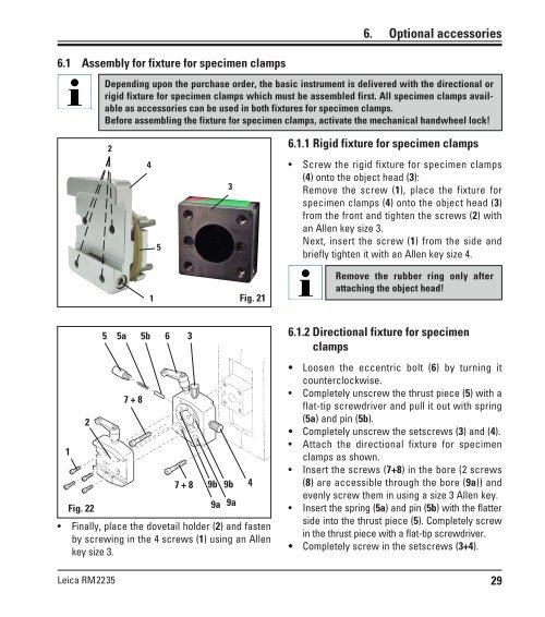
6.1 Assembly for fixture for specimen clamps<br />
1<br />
2<br />
Fig. 22<br />
Leica <strong>RM2235</strong><br />
Depending upon the purchase order, the basic instrument is delivered with the directional or<br />
rigid fixture for specimen clamps which must be assembled first. All specimen clamps available<br />
as accessories can be used in both fixtures for specimen clamps.<br />
Before assembling the fixture for specimen clamps, activate the mechanical handwheel lock!<br />
2<br />
4<br />
1<br />
5<br />
5 5a 5b 6<br />
7 + 8<br />
3<br />
3<br />
7 + 8 9b 9b<br />
9a 9a<br />
Fig. 21<br />
Finally, place the dovetail holder (2) and fasten<br />
by screwing in the 4 screws (1) using an Allen<br />
key size 3.<br />
4<br />
6. Optional accessories<br />
6.1.1 Rigid fixture for specimen clamps<br />
Screw the rigid fixture for specimen clamps<br />
(4) onto the object head (3):<br />
Remove the screw (1), place the fixture for<br />
specimen clamps (4) onto the object head (3)<br />
from the front and tighten the screws (2) with<br />
an Allen key size 3.<br />
Next, insert the screw (1) from the side and<br />
briefly tighten it with an Allen key size 4.<br />
Remove the rubber ring only after<br />
attaching the object head!<br />
6.1.2 Directional fixture for specimen<br />
clamps<br />
Loosen the eccentric bolt (6) by turning it<br />
counterclockwise.<br />
Completely unscrew the thrust piece (5) with a<br />
flat-tip screwdriver and pull it out with spring<br />
(5a) and pin (5b).<br />
Completely unscrew the setscrews (3) and (4).<br />
Attach the directional fixture for specimen<br />
clamps as shown.<br />
Insert the screws (7+8) in the bore (2 screws<br />
(8) are accessible through the bore (9a)) and<br />
evenly screw them in using a size 3 Allen key.<br />
Insert the spring (5a) and pin (5b) with the flatter<br />
side into the thrust piece (5). Completely screw<br />
in the thrust piece with a flat-tip screwdriver.<br />
Completely screw in the setscrews (3+4).<br />
29