RM2235 Manual PDF - University of Utah
RM2235 Manual PDF - University of Utah
RM2235 Manual PDF - University of Utah

Create successful ePaper yourself
Turn your PDF publications into a flip-book with our unique Google optimized e-Paper software.
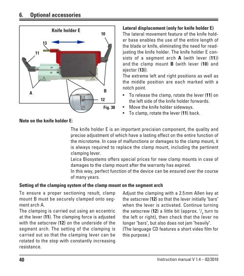
6. Optional accessories<br />
40<br />
A<br />
11<br />
13<br />
Knife holder E<br />
10<br />
B<br />
Fig. 38<br />
Lateral displacement (only for knife holder E)<br />
The lateral movement feature <strong>of</strong> the knife holder<br />
base enables the use <strong>of</strong> the entire length <strong>of</strong><br />
the blade or knife, eliminating the need for readjusting<br />
the knife holder. The knife holder E consists<br />
<strong>of</strong> a segment arch A (with lever (11))<br />
and the clamp mount B (with lever (10) and<br />
ejector (13)).<br />
The extreme left and right positions as well as<br />
the middle position are each marked with a<br />
notch point.<br />
To release the clamp, rotate the lever (11) on<br />
the left side <strong>of</strong> the knife holder forwards.<br />
Move the knife holder sideways.<br />
To clamp, rotate the lever (11) back.<br />
Note on the knife holder E:<br />
The knife holder E is an important precision component, the quality and<br />
precise adjustment <strong>of</strong> which have a lasting effect on the entire function <strong>of</strong><br />
the microtome. In case <strong>of</strong> malfunctions or damages to the clamp mount, it<br />
is always required to replace the clamp mount, including the pertinent<br />
clamping lever.<br />
Leica Biosystems <strong>of</strong>fers special prices for new clamp mounts in case <strong>of</strong><br />
damages to the clamp mount after the warranty has expired.<br />
In this way, perfect function <strong>of</strong> the device can be ensured over the course<br />
<strong>of</strong> many years.<br />
Setting <strong>of</strong> the clamping system <strong>of</strong> the clamp mount on the segment arch<br />
To ensure a proper sectioning result, clamp<br />
mount B must be securely clamped onto segment<br />
arch A.<br />
The clamping is carried out using an eccentric<br />
at the lever (11). The clamping force is adjusted<br />
with the setscrew (12) on the underside <strong>of</strong> the<br />
segment arch. The setting <strong>of</strong> the clamping is<br />
carried out so that the clamping lever can be<br />
rotated to the stop with constantly increasing<br />
resistance.<br />
12<br />
Adjust the clamping with a 2.5 mm Allen key at<br />
the setscrew (12) so that the lever initially "bars"<br />
when the lever is activated. Continue turning<br />
the setscrew (12) a little bit (approx. 1 / 4 turn to<br />
the left or right), then check that the lever no<br />
longer "bars", but also does not jam "heavily".<br />
(The language CD features a short video film for<br />
this purpose.)<br />
Instruction manual V 1.4 – 02/2010