UBI EasyCoder 401 ? Technical Manual CONTENTS
UBI EasyCoder 401 ? Technical Manual CONTENTS
UBI EasyCoder 401 ? Technical Manual CONTENTS

Create successful ePaper yourself
Turn your PDF publications into a flip-book with our unique Google optimized e-Paper software.
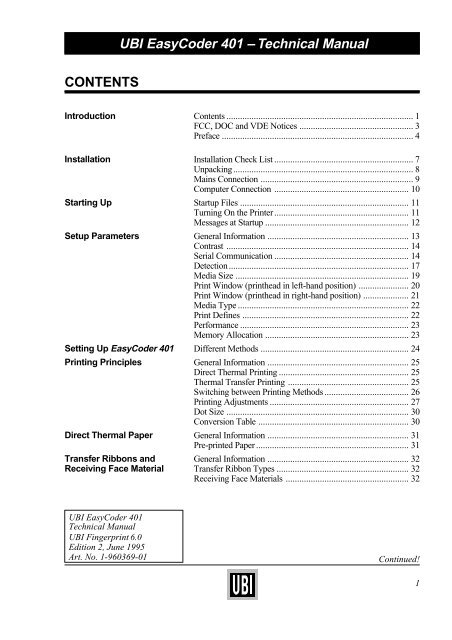
<strong>CONTENTS</strong><br />
<strong>UBI</strong> <strong>EasyCoder</strong> <strong>401</strong> – <strong>Technical</strong> <strong>Manual</strong><br />
Introduction Contents .................................................................................. 1<br />
FCC, DOC and VDE Notices .................................................. 3<br />
Preface .................................................................................... 4<br />
Installation Installation Check List ............................................................. 7<br />
Unpacking............................................................................... 8<br />
Mains Connection ................................................................... 9<br />
Computer Connection ........................................................... 10<br />
Starting Up Startup Files .......................................................................... 11<br />
Turning On the Printer........................................................... 11<br />
Messages at Startup ............................................................... 12<br />
Setup Parameters General Information .............................................................. 13<br />
Contrast ................................................................................ 14<br />
Serial Communication ........................................................... 14<br />
Detection............................................................................... 17<br />
Media Size ............................................................................ 19<br />
Print Window (printhead in left-hand position) ...................... 20<br />
Print Window (printhead in right-hand position) .................... 21<br />
Media Type ........................................................................... 22<br />
Print Defines ......................................................................... 22<br />
Performance .......................................................................... 23<br />
Memory Allocation ............................................................... 23<br />
Setting Up <strong>EasyCoder</strong> <strong>401</strong> Different Methods ................................................................. 24<br />
Printing Principles General Information .............................................................. 25<br />
Direct Thermal Printing ......................................................... 25<br />
Thermal Transfer Printing ..................................................... 25<br />
Switching between Printing Methods ..................................... 26<br />
Printing Adjustments ............................................................. 27<br />
Dot Size ................................................................................ 30<br />
Conversion Table .................................................................. 30<br />
Direct Thermal Paper General Information .............................................................. 31<br />
Pre-printed Paper ................................................................... 31<br />
Transfer Ribbons and General Information .............................................................. 32<br />
Receiving Face Material Transfer Ribbon Types .......................................................... 32<br />
Receiving Face Materials ...................................................... 32<br />
<strong>UBI</strong> <strong>EasyCoder</strong> <strong>401</strong><br />
<strong>Technical</strong> <strong>Manual</strong><br />
<strong>UBI</strong> Fingerprint 6.0<br />
Edition 2, June 1995<br />
Art. No. 1-960369-01 Continued!<br />
1
<strong>UBI</strong> <strong>EasyCoder</strong> <strong>401</strong> – <strong>Technical</strong> <strong>Manual</strong><br />
<strong>CONTENTS</strong>, cont'd.<br />
Selecting Paper/Ribbon Setup Options ........................................................................ 33<br />
Thermal Transfer Printing ..................................................... 33<br />
Direct Thermal Printing ......................................................... 34<br />
Paper Dimensions Roll Size ............................................................................... 35<br />
Non-Adhesive Strip ............................................................... 36<br />
Self-Adhesive Strip ............................................................... 37<br />
Self-Adhesive Labels ............................................................ 38<br />
Tickets with Gap ................................................................... 39<br />
Tickets with Black Mark ....................................................... 40<br />
Label-Taken Sensor General Information .............................................................. 41<br />
Adjusting the Sensitivity ........................................................ 42<br />
Program Example.................................................................. 43<br />
Paper Cutter General Information .............................................................. 44<br />
Controlling the Cutter ............................................................ 45<br />
Cleaning ................................................................................ 45<br />
Scalable Fonts Kit General Information .............................................................. 46<br />
Scaling Fonts in <strong>UBI</strong> Fingerprint........................................... 46<br />
Scaling Fonts in <strong>UBI</strong> Shell ..................................................... 46<br />
Downloading Outline Font Files from a PC ........................... 47<br />
Printout Samples ................................................................... 48<br />
Printhead Replacement Step-by-Step Instructions....................................................... 49<br />
Electronics Accessing the CPU Board ..................................................... 51<br />
CPU Board............................................................................ 52<br />
<strong>UBI</strong> Fingerprint EPROM's .................................................... 53<br />
Configuration EPROM's........................................................ 53<br />
ROM-expansion EPROM's ................................................... 53<br />
RAM memory ....................................................................... 54<br />
Real-time Clock Circuit ......................................................... 54<br />
Fuse ...................................................................................... 54<br />
Potentiometers....................................................................... 55<br />
Interfaces Communication Port "uart1:"................................................. 57<br />
RS 232C (V24) on "uart1:" .................................................... 58<br />
RS 422 on "uart1:" ................................................................ 60<br />
20 mA Current Loop on "uart1:"............................................ 62<br />
Parallel Interface Board ......................................................... 65<br />
2
FCC Notice<br />
United States of America<br />
<strong>UBI</strong> <strong>EasyCoder</strong> <strong>401</strong> – <strong>Technical</strong> <strong>Manual</strong><br />
Information in this manual is subject to change without prior notice and does not represent a commitment<br />
on the part of <strong>UBI</strong> Printer AB.<br />
© Copyright <strong>UBI</strong> Printer AB, 1995. All rights reserved. Published in Sweden.<br />
<strong>EasyCoder</strong>, LabelShop, and EasyPak are trademarks of United Barcode Industries (<strong>UBI</strong>).<br />
Apple and Macintosh are registered trademarks of Apple Computer Inc.<br />
Bitstream is a registered trademark and Speedo is a trademark of Bitstream, Inc.<br />
Centronics is a registered trademark of Centronics Data Computer Corp.<br />
IBM is a registered trademark of International Business Machines Corporation.<br />
Microsoft, MS, and MS-DOS are registered trademarks of Microsoft Corporation.<br />
Torx is a registered trademark of Camcar Division of Textron Inc.<br />
TrueType is a trademark of Apple Computer Inc.<br />
Windows is a trademark of Microsoft Corporation.<br />
WARNING:<br />
This equipment generates, uses, and can radiate radio frequency energy and if not installed and used in accordance with<br />
the instructions manual, may cause interference to radio communications. It has been tested and found to comply with the<br />
limits for a Class A computing device pursuant to Subpart J of Part 15 of FCC Rules, which are designed to provide<br />
reasonable protection against such interference when operated in a commercial environment. Operation of this equipment<br />
in a residential area is likely to cause interference in which case the user at his own expense will be required to take whatever<br />
measures may be required to correct the interference.<br />
DOC Notice<br />
Canada<br />
Canadian Dept. of Communication<br />
REGULATIONS COMPLIANCE<br />
(DOC-A)<br />
This digital apparatus does not exceed the class A limits for radio noise emissions from a digital apparatus as set out in<br />
the radio interference regulations of the Canadian Department of Communication.<br />
✳ ✳ ✳<br />
Ministère des Communications du Canada<br />
CONFORMITE DE REGLEMENTS<br />
(DOC-A)<br />
Le présent appareil numérique n´émet pas de bruits radio-électriques dépassant les limites applicables aux appareils<br />
numériques de classe A prescrites dans le règlement sur brouillage radioélectrique édicté par le Ministère des<br />
Communications du Canada.<br />
VDE Notice<br />
Germany<br />
ALLGEMEINE VORSCHRIFT:<br />
Reparaturen oder sonstige Eingriffe, die sich nicht auf normale Bedienung der Maschine beziehen, dürfen ausschließlich<br />
nur von einem ausgebildeten, zuständigen Fachmann vorgenommen werden.<br />
3
PREFACE<br />
<strong>UBI</strong> <strong>EasyCoder</strong> <strong>401</strong> – <strong>Technical</strong> <strong>Manual</strong><br />
This <strong>Technical</strong> <strong>Manual</strong> is intended to facilitate installation and<br />
setup. It also gives information on labels, tickets, tags, paper strip<br />
and thermal transfer ribbons. Compared to edition 1, this edition<br />
includes information on the <strong>UBI</strong> Fingerprint 6.0 software. This<br />
manual is presently supplemented by the following publications:<br />
• <strong>EasyCoder</strong> <strong>401</strong>, Operator's Guide<br />
Illustrated step-by-step instructions for paper and ribbon load as well as daily<br />
maintenance. Multilingual.<br />
• <strong>EasyCoder</strong> <strong>401</strong>, User's <strong>Manual</strong>s<br />
Gives information on how to run and maintain the printer, how to load paper<br />
supply, and – in case thermal transfer printers – how to load the transfer ribbon.<br />
• <strong>UBI</strong> Shell Standard Startup <strong>Manual</strong><br />
Gives information on how to run the <strong>UBI</strong> Shell startup program.<br />
• <strong>EasyCoder</strong> <strong>401</strong>, Service <strong>Manual</strong><br />
Gives information on troubleshooting, adjustments and repair of the <strong>EasyCoder</strong><br />
<strong>401</strong> printer.<br />
• <strong>EasyCoder</strong> <strong>401</strong>, Spare Parts & Options<br />
Illustrates the various spare parts and field-installable options.<br />
• <strong>UBI</strong> Direct Protocol, Programmer's Guide<br />
Introduction to the <strong>UBI</strong> Direct Protocol, an easy-to-use “slave” protocol for<br />
computer connection.<br />
• <strong>UBI</strong> Fingerprint, Programmer's Guide<br />
Introduction to the <strong>UBI</strong> Fingerprint programming language, which is used to<br />
control the printer's functions and the printing.<br />
• <strong>UBI</strong> Fingerprint, Reference <strong>Manual</strong><br />
Contains information on the instructions and other features in the <strong>UBI</strong><br />
Fingerprint programming language.<br />
• <strong>UBI</strong> LabelShop, Operator's <strong>Manual</strong><br />
Information on how to use the <strong>UBI</strong> LabelShop WYSIWYG label-editing<br />
program for Microsoft Windows.<br />
• <strong>UBI</strong> Windows Driver, Installation Instruction<br />
Information on how to install and use the <strong>UBI</strong> Windows Driver.<br />
• <strong>UBI</strong> Macintosh Driver, Installation Instruction<br />
Information on how to install and use the <strong>UBI</strong> Macintosh Driver.<br />
4
<strong>UBI</strong> <strong>EasyCoder</strong> <strong>401</strong> – <strong>Technical</strong> <strong>Manual</strong><br />
PREFACE, cont'd.<br />
Power Ready Error<br />
<strong>EasyCoder</strong> <strong>401</strong><br />
Print<br />
The <strong>UBI</strong> <strong>EasyCoder</strong> <strong>401</strong> is a rugged industrial thermal transfer/direct thermal printer<br />
intended for low volume label production of max. 1,000 – 2,000 labels/day.<br />
The <strong>EasyCoder</strong> <strong>401</strong> is fitted with the <strong>UBI</strong> Fingerprint software, which is compatible<br />
with the <strong>UBI</strong> LabelShop label-editing program, the <strong>UBI</strong> Windows Driver (optional<br />
parallel interface board required), the <strong>UBI</strong> Macintosh Driver and the <strong>UBI</strong> Direct<br />
Protocol. The flexible <strong>UBI</strong> Fingerprint programming language also allows you to<br />
create your own programs.<br />
Optionally, the <strong>EasyCoder</strong> <strong>401</strong> can be fitted with a scalable fonts kit that allows the use<br />
of outline fonts in Speedo and TrueType format, a paper cutter or a label-taken sensor,<br />
and a real-time clock circuit.<br />
5
<strong>UBI</strong> <strong>EasyCoder</strong> <strong>401</strong> – <strong>Technical</strong> <strong>Manual</strong><br />
PREFACE, cont'd.<br />
Feature <strong>EasyCoder</strong> <strong>401</strong> Notes<br />
Print Technique Direct Thermal & Thermal Transfer<br />
Quick-Mount Printhead 8 dots/mm (203.2 dpi) Thick-film technique<br />
Print Width max. 104 mm (4.09")<br />
Media Width max. 120 mm (4.7")<br />
Print Length max. 1250 mm (49.2")<br />
Print Speed max. 100 mm/sec. (4"/sec.)<br />
Fonts, expandible 4 times Standard: 10 Bitmapped 1 Min. 1 Bitmapped<br />
Smooth Fonts Yes, with <strong>UBI</strong> Toolbox or Scalable Fonts Kit 2<br />
Print Directions for Text, Images, Lines, and Boxes 4<br />
Bar Code Generators Depends on software version 1<br />
Internal Paper Roll Diameter max. 152 mm (6.0")<br />
Ribbon Length 450 m (1476 ft.)<br />
Keyboard, built-in Print key only<br />
Display 2 lines x 16 characters LCD<br />
Dimensions (W x D x H) 275 x 382 x 239 mm (10.8 x 15 x 9.4")<br />
Weight (excl. paper, ribbon and options) 14.0 kgs (31 lbs)<br />
Ambient Operating Temperature + 5˚C – +40˚C (+41˚F – +104˚F) Applies to printer –not to media<br />
Humidity 20–80% non-condensing Applies to printer –not to media<br />
Sound Emission Level < 60 dB (A)<br />
Microprocessor 32 bit<br />
Programming Language <strong>UBI</strong> Fingerprint Incl. <strong>UBI</strong> Direct Protocol<br />
Startup program <strong>UBI</strong> Shell Standard<br />
On-Board RAM Memory, standard 256 kbytes Max. 512 kbytes 2<br />
Label and Ribbon End Sensors Standard<br />
Mains Voltage 115/230 VAC +10/-15%, 2.6/1.3 A 60/50 Hz Selected by means of a switch<br />
Max. Power Consumption 300 W<br />
Communication Interface, standard RS 232C Prepared for RS 422/20 mA CL<br />
1 x Centronics Interface 2 Optional On separate interface board<br />
RS 232C Cable 2 Optional<br />
Centronics Cable 2 Optional<br />
Label-Taken Sensor (LTS) 2 Optional<br />
Real-Time Clock Circuit Optional<br />
External RS 232C Alphanumeric keyboard 2 Optional<br />
Quick-Load Ribbon Cassette 2 Optional<br />
Paper Cutter Unit 2 Optional<br />
Label Roll Retainer 2 Optional<br />
Guides for External Fan-Fold Paper Supply 2 Optional<br />
Scalable Fonts Kit 2 Optional Scales Speedo and TrueType fonts<br />
<strong>UBI</strong> Toolbox, PC Windows configuration support 2 Optional<br />
<strong>UBI</strong> LabelShop, WYSIWYG Label Software for Windows 2 Optional<br />
<strong>UBI</strong> Windows Driver 2 (excl. cable) Optional<br />
<strong>UBI</strong> Macintosh Driver 2 (incl. cable) Optional<br />
1 /. See <strong>UBI</strong> Fingerprint manuals<br />
2 /. Options to be installed by user or reseller<br />
6
INSTALLATION<br />
<strong>UBI</strong> <strong>EasyCoder</strong> <strong>401</strong> – <strong>Technical</strong> <strong>Manual</strong><br />
Installation Check List ❑ Unpack the printer as described on next page.<br />
❑ Standard <strong>EasyCoder</strong> printer:<br />
If you have a standard <strong>EasyCoder</strong> <strong>401</strong> printer, go on to next step.<br />
Customized <strong>EasyCoder</strong> printer:<br />
If you have a customized <strong>EasyCoder</strong> <strong>401</strong> printer, check its CPU<br />
board and possible parallel interface board in regard of interface<br />
circuits and straps as described in the chapters “Electronics”<br />
and “Interfaces” at the end of this manual. Then go on to next<br />
step.<br />
❑ Connect the printer to a mains socket as described later on in this<br />
chapter.<br />
❑ Connect the printer to its host computer by means of a suitable<br />
communication cable as described later in this chapter. (Refer to<br />
the chapter “Interfaces” for more information on computer<br />
connection and cable configurations).<br />
❑ Load a supply of paper and thermal transfer ribbon, or thermal<br />
paper only, see the User's <strong>Manual</strong>. Be careful to adjust the<br />
position of the label stop sensor so it will detect the front edge of<br />
the labels, tickets or tags, or optionally the black marks at the<br />
back of the paper web.<br />
❑ Check that the printhead is lowered.<br />
❑ If the printer is fitted with an optional paper cutter, check that the<br />
cutter unit is locked in closed position.<br />
❑ Turn on the power.<br />
❑ Proceed according to the chapter “Starting Up”.<br />
7
<strong>UBI</strong> <strong>EasyCoder</strong> <strong>401</strong> – <strong>Technical</strong> <strong>Manual</strong><br />
INSTALLATION, cont'd.<br />
Unpacking<br />
Machine Sign<br />
Before starting the installation, carefully examine the delivery for<br />
possible damage or missing parts:<br />
❑ Open the box and lift the printer, together with the foam-plastic<br />
shock absorbers, out of the box.<br />
❑ Remove the shock absorbers and check that the machine has not<br />
been visibly damaged during the transportation. Keep the packing<br />
material until you are sure that the printer functions properly.<br />
❑ The machine sign on the printer's rear plate gives information on:<br />
• Type<br />
• Article number<br />
• Serial number<br />
❑ Check the printer in regard to possible options ordered.<br />
❑ Check that the mains cord has a pin configuration that will fit into<br />
a wall socket according to the local standard.<br />
Should any kind of damage have occurred during transportation,<br />
immediately make a complaint to the carrier.<br />
Any incorrect delivery or missing parts should be reported to the<br />
distributor.<br />
0<br />
230V<br />
TA<br />
Type<br />
Art. No.<br />
Ser. No.<br />
115/230 V 2.6/1.3 A 50–60 Hz<br />
MADE IN SWEDEN<br />
European type US/Canadian type GB type<br />
230V mains plug 115V mains plug 230V mains plug<br />
8
Mains Connection<br />
<strong>UBI</strong> <strong>EasyCoder</strong> <strong>401</strong> – <strong>Technical</strong> <strong>Manual</strong><br />
INSTALLATION, cont'd.<br />
Power Ready Error<br />
<strong>EasyCoder</strong> <strong>401</strong><br />
Power On LED<br />
❑ Make sure that the printer is set for the correct voltage by<br />
checking the voltage switch-over on the printer's rear plate.<br />
❑ Fit the mains cord, which is included in the delivery, into the<br />
mains receptacle. Connect the other end of the cord to a<br />
grounded wall socket. To avoid interference from noise, surges<br />
and spikes, a dedicated line is preferred. If no such line is<br />
available, avoid lines to which electric motors, refrigerators and<br />
similar devices are connected.<br />
❑ The power can be turned on/off by means of the main switch<br />
situated above the mains receptacle. The “Power” LED on the<br />
printer's keyboard indicates when the power is on.<br />
Print<br />
0<br />
230V<br />
TA<br />
Type<br />
Art. No.<br />
Ser. No.<br />
115/230 V 2.6/1.3 A 50–60 Hz<br />
MADE IN SWEDEN<br />
Mains Receptacle<br />
Voltage Switch-over<br />
Main Switch<br />
9
<strong>UBI</strong> <strong>EasyCoder</strong> <strong>401</strong> – <strong>Technical</strong> <strong>Manual</strong><br />
INSTALLATION, cont'd.<br />
Computer Connection<br />
WARNING!<br />
When connecting printer and host,<br />
the power should be off!<br />
<strong>UBI</strong> Standard Cables<br />
RS 232C Cables:<br />
Printer to IBM-AT 1-975581-05<br />
Printer to IBM-XT/PS2 1-975580-05<br />
Printer to Mac 1-010007-00<br />
DB-25 Gender Changer<br />
Centronics Cable:<br />
1-010008-00<br />
DB-25/Centronics 1-010001-00<br />
<strong>EasyCoder</strong> <strong>401</strong> is always fitted with one communication port<br />
("uart1:") for RS 232C on the rear plate.<br />
As an option, this communication port can be reconfigured for<br />
either RS 422 or 20 mA Current Loop after additional circuits have<br />
been fitted on the CPU board, see chapter “Interfaces”.<br />
The <strong>EasyCoder</strong> <strong>401</strong> can also be fitted with an optional parallel<br />
interface board, e.g. for use with the <strong>UBI</strong> Windows Driver.<br />
With the exception of the <strong>UBI</strong> Macintosh Driver kit, no communication<br />
cable is provided unless ordered separately. Refer to the<br />
chapter “Interfaces” for cable configuration descriptions.<br />
Refer to the manual of the host computer or terminal for information<br />
on how to connect the other end of the communication cable.<br />
0<br />
230V<br />
Type<br />
Art. No.<br />
Ser. No.<br />
115/230 V 2.6/1.3 A 50–60 Hz<br />
MADE IN SWEDEN<br />
Hints:<br />
• For <strong>UBI</strong> LabelShop, <strong>UBI</strong> Direct Protocol or <strong>UBI</strong> Fingerprint programming,<br />
use the "uart1:" serial RS 232C communication channel.<br />
• For <strong>UBI</strong> Windows Driver, use the "centronics:" parallel communication<br />
channel.<br />
• For the <strong>UBI</strong> Macintosh Driver, use the "uart1:" serial communication<br />
channel. A special cable with gender changer is included in the driver kit.<br />
• <strong>UBI</strong>'s standard communication cables and adapters makes it possible to<br />
connect the printer directly to the serial or parallel port of an IBM AT, XT or<br />
PS-2 personal computer, or the serial port of an Apple Macintosh computer.<br />
TA<br />
Parallel Port<br />
36-p female Centronics<br />
(option)<br />
Serial RS 232C Port<br />
DB25 male<br />
10
STARTING UP<br />
Startup Files<br />
<strong>UBI</strong> <strong>EasyCoder</strong> <strong>401</strong> – <strong>Technical</strong> <strong>Manual</strong><br />
EPROM = Erasable Programmable<br />
Read-Only Memory<br />
RAM = Random Access Memory<br />
ROM = Read-Only Memory<br />
Turning On the Printer<br />
At startup, the behaviour of the printer is decided by the possible<br />
existence of a startup (autoexec) file, i.e. a program that automatically<br />
starts running when the printer is turned on, somewhere in the<br />
printer's memory. There are three major possibilities:<br />
A The printer is fitted with the <strong>UBI</strong> Shell file-managing program,<br />
which allows the operator to choose between a variety of<br />
applications and functions.<br />
B The printer is fitted with no startup file at all.<br />
C The printer is fitted with a custom-made application program<br />
that is design to perform a specific task, e.g. to print airline<br />
tickets, baggage tags, or product labels for a certain company.<br />
There can be one startup file stored in each of the following parts of<br />
the printer's memory: RAM and ROM. If there are startup files<br />
stored in more than one place, they will be used with the following<br />
priority:<br />
1. Printer's RAM memory.<br />
2. Printer's ROM memory, e.g. the configuration EPROM's.<br />
This implies that if you have a startup file stored in the configuration<br />
EPROM's and another in the printer's RAM memory<br />
when you turn on the printer, the startup file in the RAM memory<br />
will be used.<br />
The display will keep you informed on what happens and in many<br />
cases prompt you to take some kind of action, e.g. to choose<br />
between options. How to take action depends on the startup<br />
program.<br />
Do not start the printer before you have made the necessary<br />
connections, inserted any memory card you want to use, and<br />
checked that the printhead is lowered and the optional cutter is in<br />
closed position.<br />
Turn on the power by means of the main switch on the rear plate.<br />
The “Power” LED control lamp on the front panel lights up when<br />
the power is on. Wait for a few moments, while the printer loads the<br />
program and runs some self-diagnostic tests. Then some kind of<br />
message will appear in the display window.<br />
11
<strong>UBI</strong> <strong>EasyCoder</strong> <strong>401</strong> – <strong>Technical</strong> <strong>Manual</strong><br />
STARTING UP, cont'd.<br />
Messages at Startup<br />
The type of startup file running in the printer is indicated by the<br />
message shown in the display window directly after power up.<br />
A. <strong>UBI</strong> Shell Startup Program (standard in <strong>EasyCoder</strong> <strong>401</strong>):<br />
PRINT=<strong>UBI</strong> SHELL or ENTER=<strong>UBI</strong> SHELL<br />
5 sec. v.4.0 5 sec. v.4.0<br />
4 sec. v.4.0 4 sec. v.4.0<br />
3 sec. v.4.0 3 sec. v.4.0<br />
2 sec. v.4.0 2 sec. v.4.0<br />
1 sec. v.4.0 1 sec. v.4.0<br />
Refer to the <strong>UBI</strong> Shell Standard Startup <strong>Manual</strong>. The digits in the<br />
lower right corner of the display indicate the version of <strong>UBI</strong> Shell.<br />
B. No Startup File (non-standard <strong>EasyCoder</strong> <strong>401</strong>):<br />
<strong>UBI</strong> Fingerprint<br />
6.0<br />
Refer to the documentation of the corresponding version of <strong>UBI</strong><br />
Fingerprint for further information.<br />
C. Custom-made Application Program (non-standard <strong>EasyCoder</strong> <strong>401</strong>):<br />
Any other display message than those illustrated above indicate that<br />
the printer is running some custom-made, non-standard application<br />
program or that some error has occurred.<br />
12
General Information<br />
<strong>UBI</strong> <strong>EasyCoder</strong> <strong>401</strong> – <strong>Technical</strong> <strong>Manual</strong><br />
SETUP PARAMETERS<br />
The setup allows you to adapt the printer for the desired type of<br />
computer communication and to control the printing. The setup<br />
parameters are:<br />
Parameter Options Default 1<br />
❑ Contrast<br />
❑ Ser-Com<br />
Variable (0–10) Middle (5)<br />
2 :<br />
◆ Baudrate 300 | 600 | 1200 | 2400 | 4800 | 9600 | 19200 9600<br />
◆ Parity even | odd | mark | space | none none<br />
◆ Char length 7 bits | 8 bits 7 bits<br />
◆ Stop bits<br />
◆ Flow control:<br />
1 bit | 2 bits 2 bits<br />
- RTS/CTS Enable | disable disable<br />
- ENQ/ACK Enable | disable disable<br />
- XON/XOFF, data from host Enable | disable enable<br />
- XON/XOFF, data to host Enable | disable enable<br />
◆ New line<br />
❑ Detection:<br />
CR/LF | LF | CR CR/LF<br />
◆ LSS adjust<br />
◆ Feedadj:<br />
Variable n.a.<br />
- Startadj Variable ± 0<br />
- Stopadj<br />
❑ Service:<br />
◆ Media size:<br />
Variable ± 0<br />
- X-start Variable (0 – 831) 0<br />
- Width Variable (0 – 832) 832<br />
- Length Unlimited 1200<br />
◆ Media type: Label (w gaps) | Ticket (w mark) | Ticket (w gaps) |<br />
◆ Print defs:<br />
Fix length strip | Var length strip Label (w gaps)<br />
- Head resist Set automatically at startup n.a.<br />
- Paper type Select supply option. See chapter “Selecting Paper/Ribbon” <strong>UBI</strong> HP 20<br />
- New supplies Select a new type of supply by means of a 13-digit code n.a.<br />
- Testprint A series of test labels can be printed n.a.<br />
◆ Performance3 :<br />
◆ Memory alloc:<br />
Normal | High | Ultrahigh Normal<br />
- Image buff size Variable 48 kbyte<br />
- Rec buf size2 Variable 300 byte<br />
- Trans buf size2 Variable 300 byte<br />
1 /. “Default” refers to the default setup values in the standard configuration EPROM's. A custom-made printer fitted with<br />
non-standard configuration EPROM's may have a different combination of default setup values.<br />
2 /. There is no communication setup and no receive and transmit buffers for the optional parallel communication channel.<br />
3 /. All three options relate to the same nominal print speed.<br />
13
<strong>UBI</strong> <strong>EasyCoder</strong> <strong>401</strong> – <strong>Technical</strong> <strong>Manual</strong><br />
SETUP PARAMETERS, cont'd.<br />
Contrast<br />
Serial Communication<br />
• Baudrate<br />
• Parity<br />
• Character Length<br />
• Stop Bits<br />
• Flow Control<br />
• New Line<br />
This chapter explains the meaning of the various setup parameters.<br />
There are several ways to change the setup:<br />
• By means of the Terminal Setup option in <strong>UBI</strong> Shell, see the <strong>UBI</strong><br />
Shell Standard Startup <strong>Manual</strong>.<br />
• By means of setup files or setup strings. See the <strong>UBI</strong> Fingerprint<br />
Reference <strong>Manual</strong>, SETUP statement, or the <strong>UBI</strong> Direct Protocol<br />
Programmer's Guide.<br />
The contrast setup allows you to make minor adjustment of the<br />
printout in regard of blackness, e.g. to adapt the printer to variations<br />
in quality between different batches of the same paper quality.<br />
The serial communication setup controls the communication between<br />
the printer and the connected computer or other devices on<br />
the standard serial channel "uart1:".<br />
The serial communication setup has no consequence whatsoever<br />
for parallel communication via an optional parallel interface<br />
board.<br />
For the serial communication channel, the following parameters<br />
can be set. Make sure they match the setup of the connected device<br />
or vice versa. The default setup (indicated by bold characters below)<br />
is selected as to make the printer understand and act upon <strong>UBI</strong><br />
Fingerprint instructions transmitted from the host, regardless how<br />
the host is set up. If the setup of the printer and the setup of the host<br />
do not match, the response from the printer to host will be garbled.<br />
• Baudrate:<br />
The baudrate is the transmission speed in bits per second. The<br />
following baudrates can be selected:<br />
300<br />
600<br />
1200<br />
2,400<br />
4,800<br />
9,600 Max. recommended baudrate for 20 mA current loop<br />
19,200<br />
If communication problems occur, try a lower baudrate.<br />
Continued!<br />
14
<strong>UBI</strong> <strong>EasyCoder</strong> <strong>401</strong> – <strong>Technical</strong> <strong>Manual</strong><br />
SETUP PARAMETERS, cont'd.<br />
Serial Communication,<br />
cont'd.<br />
• Parity:<br />
The parity decides how the software will check for transmission<br />
errors. There are five options:<br />
None<br />
Even<br />
Odd<br />
Mark<br />
Space<br />
• Character Length:<br />
The character length specifies the number of bits in a character.<br />
For most purposes 7 bits will be sufficient, but if special characters<br />
or characters specific for other languages are to be used, 8 bits are<br />
recommended. Refer to the <strong>UBI</strong> Fingerprint Reference <strong>Manual</strong><br />
for information on which characters are available in various<br />
combinations of character length and character set.<br />
7 Characters ASCII 0 – 127 decimal can be transmitted.<br />
8 Characters ASCII 0 – 255 decimal can be transmitted.<br />
• Stop Bits:<br />
The number of stop bits specifies how many bits will define the<br />
end of a character. There are two options:<br />
1<br />
2<br />
• Flowcontrol:<br />
There are several different ways to control the exchange of data<br />
between the printer and the connected computer or other device<br />
(“Handshaking”). Each option can be enabled or disabled<br />
separately, but normally only one alternative should be selected.<br />
For galvanically insulated interfaces, i.e. 20 mA current loop and<br />
RS 422, ENQ/ACK or XON/XOFF are to prefer in order to retain<br />
interference protection and limit the number of lines.<br />
• Flowcontrol, cont'd:<br />
RTS/CTS<br />
This is a protocol where the communication is controlled by currents through<br />
separate lines in the cable being set either to high or low. By default, this option is<br />
disabled.<br />
RTS high indicates that the transmitting unit is able to receive characters. RTS low<br />
indicates that the receive buffer is filled to 75% (see XON/XOFF).<br />
CTS high indicates that the unit transmitting the CTS signal is ready to receive data.<br />
CTS low indicates that the receive buffer is full (see XON/XOFF). In some computer<br />
programs, e.g. MS Windows Terminal, RTS/CTS is designated “Hardware”.<br />
Continued!<br />
15
<strong>UBI</strong> <strong>EasyCoder</strong> <strong>401</strong> – <strong>Technical</strong> <strong>Manual</strong><br />
SETUP PARAMETERS, cont'd.<br />
Serial Communication,<br />
cont'd.<br />
DTR<br />
DTR (“Data Terminal Ready”) is signal, which is not controlled in the setup mode,<br />
but by straps on the CPU board or interface board. DTR high indicates that the<br />
transmitting unit is turned on.<br />
ENQ/ACK<br />
In this protocol, the communication is controlled by the special characters ENQ<br />
(ASCII 05 dec.) and ACK (ASCII 06 dec.) being transmitted on the same line as the<br />
data. The sending unit transmits ENQ at regular intervals. If the response ACK is not<br />
received the transmission is held up awaiting an ACK character from the receiving<br />
unit. By default, this option is disabled.<br />
XON/XOFF<br />
In this protocol, the communication is controlled by the special characters XON<br />
(ASCII 17 dec.) and XOFF (ASCII 19 dec.) being transmitted on the same line as the<br />
data. XON/XOFF can be enabled/disabled separately for data received from the<br />
host by the printer (printer sends XON/XOFF), and for data transmitted to the host<br />
from the printer (host sends XON/XOFF).<br />
XOFF is sent from the printer when its receive buffer is filled by 75%, and the<br />
transmission from the host is held up awaiting an XON character. When enough<br />
data have been processed that the receive buffer is filled only to 50%, the printer<br />
sends an XON character and the host resumes transmitting data. The same<br />
principles apply to XON/XOFF sent by the host, even if the percentage may differ.<br />
By default, XON/XOFF is enabled for data both ways.<br />
• New Line:<br />
This setup parameter allows you select the character(s) transmitted<br />
from the printer to specify the switching to a new line. There are<br />
three options:<br />
CR/LF ASCII 13 dec. + ASCII 10 dec.<br />
LF ASCII 10 dec.<br />
CR ASCII 13 dec.<br />
16
<strong>UBI</strong> <strong>EasyCoder</strong> <strong>401</strong> – <strong>Technical</strong> <strong>Manual</strong><br />
SETUP PARAMETERS, cont'd.<br />
Detection<br />
• LSS Adjustment<br />
• Feed Adjustment<br />
Emitter<br />
Emitter and<br />
Receiver<br />
The upper part of the LSS is a light emitter<br />
for labels, tickets and strip, whereas the<br />
lower part contains both a receiver and<br />
an emitter for black mark detection.<br />
Handle<br />
The inner edge of the handle indicates the<br />
position of the LSS.<br />
Note!<br />
Printers fitted with a ribbon save device<br />
have different type of label stop/black<br />
mark sensor mechanism, where the<br />
lateral position of the sensor is adjusted<br />
by means of a screw instead of a handle,<br />
see chapter “Ribbon Save Device” later<br />
in this manual.<br />
The Detection facilities are used to adjust the label stop/black mark<br />
sensor (LSS) and to control the paper feed.<br />
LSS Adjustment:<br />
The LSS is a photo-electric detection device that controls the paper<br />
feed. Situated inside the printing mechanism, it detects the front<br />
edges of the labels, slits in tickets or tags, or black marks at the back<br />
of the paper web.<br />
If the printer is set up for “Label (w gaps)”, “Ticket (w gaps)”, “Fix<br />
length strip”, or “Var. length strip”, a narrow beam of light is<br />
emitted from the upper part of the LSS and received by the sensor<br />
in the lower part. Non-transparent paper will block the beam<br />
completely, whereas semi-transparent backing paper between labels<br />
will allow some of the light to pass through. A detection gap in<br />
the ticket web causes no interference at all. An out-of-paper<br />
condition is assumed, when no interference to the beam has been<br />
detected within a feed length corresponding to the distance between<br />
the dot line on the printhead and the sensor.<br />
When the printer is set up for “Ticket (w mark)”, the light is emitted<br />
from the lower part of the LSS. The beam can be reflected back to<br />
the receiver by the white paper at the back of the web. If the beam<br />
hits a black mark, practically no light will be reflected back . An outof-paper<br />
condition is assumed, when no reflected light has been<br />
detected within a feed length corresponding to the distance between<br />
the dot line on the printhead and the sensor.<br />
Obviously, it is important that the printer is set up for the correct type<br />
of media (see “Media Type” later in this chapter) so the software<br />
can interpret the signals correctly.<br />
The LSS can be moved max. 50 mm sideways across the web. The<br />
inner edge of the handle indicates the lateral position of the sensor.<br />
The LSS is automatically fine-adjusted when a Testfeed operation<br />
is performed. Moreover, the LSS emitters can be adjusted in regard<br />
of light intensity in the Setup Mode or by means of setup files and<br />
the LSS receiver can be adjusted by means of a potentiometer on the<br />
CPU board (see the chapter “Electronics/Potentiometers”).<br />
If the printer works as expected, there is no need to adjust the LSS,<br />
but if the printer starts to feed out labels or tickets in an unexpected<br />
manner, check that the sensor is properly aligned in relation to the<br />
web and that it has not become dirty. Perform a few Testfeed<br />
operations to allow the sensor to auto-adjust itself.<br />
If the error remains, proceed according to the description of the<br />
Setup Mode for the printer model in question. Only as a last resort<br />
should the potentiometer be adjusted.<br />
Continued!<br />
17
<strong>UBI</strong> <strong>EasyCoder</strong> <strong>401</strong> – <strong>Technical</strong> <strong>Manual</strong><br />
SETUP PARAMETERS, cont'd.<br />
Detection, cont'd.<br />
TPH density 8 dots/mm (203.2 dpi):<br />
1 dot = 0.125 mm = 4.92 mils<br />
Rec. adjustments:<br />
Density:<br />
Tear Off:<br />
Value<br />
Start adjust: -114<br />
Stop adjust:<br />
Strip:<br />
0<br />
Start adjust: -114<br />
Stop adjust:<br />
Cutting between labels:<br />
70<br />
Start adjust: -294<br />
Stop adjust: +180<br />
Cutting variable length strip:<br />
Start adjust: -294<br />
Stop adjust: +250<br />
For more information on the instructions<br />
FORMFEED and PRINTFEED, see <strong>UBI</strong><br />
Fingerprint Reference <strong>Manual</strong> or <strong>UBI</strong><br />
Direct Protocol Programmer's Guide.<br />
Feed Adjustment:<br />
The Feed Adjustment contains two parameters, Start adjustment<br />
and Stop adjustment, that will be effected regardless of which<br />
program is run. Such global adjustments can be further modified for<br />
various purposes by the use of FORMFEEDs within the currently<br />
running program.<br />
Note:<br />
It is possible to turn off the label stop sensor for a certain amount<br />
of paper feed, and to override the start adjustment and stop<br />
adjustment setup by means of the LBLCOND statement, see <strong>UBI</strong><br />
Fingerprint manuals.<br />
The Start Adjustment is given as a positive or negative number of<br />
dots:<br />
•A positive start adjustment means that the specified length of<br />
paper web will be fed out before the printing starts. Accordingly,<br />
the origo is moved away from the forward edge of the copy. (This<br />
has the same effect as a positive FORMFEED before a PRINTFEED).<br />
•A negative start adjustment means that the specified length of<br />
paper web will be pulled back before the printing starts.<br />
Accordingly, the origo is moved towards the forward edge of the<br />
copy. (This has the same effect as a negative FORMFEED before<br />
a PRINTFEED).<br />
The Stop Adjustment is set up the same way.<br />
•A positive stop adjustment means that the specified length of<br />
paper web will be fed out after the printing is completed.<br />
Accordingly, the origo is moved away from the forward edge of<br />
next copy. (This has the same effect as a positive FORMFEED after<br />
a PRINTFEED).<br />
•A negative stop adjustment means that the specified length of<br />
paper web will be pulled back after the printing is completed.<br />
Accordingly, the origo is moved towards the forward edge of next<br />
copy. (This has the same effect as a negative FORMFEED after a<br />
PRINTFEED).<br />
18
<strong>UBI</strong> <strong>EasyCoder</strong> <strong>401</strong> – <strong>Technical</strong> <strong>Manual</strong><br />
SETUP PARAMETERS, cont'd.<br />
Media Size<br />
• X-start<br />
• Width<br />
• Length<br />
TPH density 8 dots/mm (203.2 dpi):<br />
1 dot = 0.125 mm = 4.92 mils<br />
Note!<br />
It is important to change the width<br />
setup whenever a narrow paper<br />
is used. Never print outside the<br />
paper web! That may cause damage<br />
to the printhead by overheating,<br />
since the paper serves as a<br />
cooling media for the printhead<br />
dots.<br />
X-start, Width and Length:<br />
To protect the printhead from the potentially harmful condition of<br />
printing outside the paper web, a printable area must be specified by<br />
the use of the setup parameters X-start, Width and Length.<br />
❑ X-start specifies the position of the origo along the dots on the<br />
printhead. By default, X-start is set as 0, i.e. at dot No. 0 which<br />
is the dot closest to the printer's centre-line wall.<br />
Number of dots: 832<br />
Outermost dot number: 831<br />
Max. print width: 104 mm (≈ 4.1")<br />
By setting a value larger than 0 for the X-start parameter, you will<br />
move the origo outwards, away from the inner edge of the web.<br />
In other words, the larger X-start value – the wider inner margin<br />
and the less printable area.<br />
❑ Width specifies the width of the printable area and is defined as<br />
a number of dots from the origo. The sum of the X-start value and<br />
the width value gives the outer margin of the printable area, as<br />
illustrated on next page. The width must not be so large as to<br />
allow printing outside the paper web.<br />
❑ Length serves three purposes:<br />
• To decide the length of the printable area from origo and along<br />
the Y-coordinate as a number of dots.<br />
• To decide the amount of paper feed when using “fix length<br />
strip”.<br />
• To set an “emergency stop”, which works when the printer is<br />
set up for “Label (w gaps)”, “Ticket (w mark)”, or “Ticket (w<br />
gaps)”. If the LSS has not detected a gap or mark within 150%<br />
of the set length, the paper feed is automatically stopped to<br />
avoid feeding out a whole roll of paper, e.g. because of a<br />
blocked or faulty LSS.<br />
This implies that you can use labels or tickets longer than the<br />
printable area:<br />
Max. printable area (9999 dots): 1,250 mm (49.2")<br />
Max. label or ticket length: 1,875 mm (73.8")<br />
By setting up the X-start, the Width and the Length, you will<br />
create a “print window” in which the printing can be performed.<br />
Any object or field protruding outside the print window in any<br />
direction will cause an error condition (Error 1003 “Field out of<br />
label”) and the printing will be inhibited.<br />
Continued!<br />
19
<strong>UBI</strong> <strong>EasyCoder</strong> <strong>401</strong> – <strong>Technical</strong> <strong>Manual</strong><br />
SETUP PARAMETERS, cont'd.<br />
Print Window:<br />
Printhead in left-hand position<br />
Dot-line<br />
on printhead<br />
Dot 0<br />
Length<br />
Origo<br />
X-start Width<br />
The printhead can be fitted in two positions (see chapter “Printhead<br />
Replacement”). When the printhead is fitted in the innermost, lefthand<br />
position (see illustration), dot No. 0 is aligned with the inner<br />
edge of the paper web. Since the maximum print width is 104 mm<br />
(4.1") and the maximum web width is 120 mm (4.7"), this leaves a<br />
margin of at least 16 mm (0.6") along the outer edge of the web,<br />
where no printing can be performed.<br />
From<br />
paper supply<br />
104 mm (4.1")<br />
PRINT PRINT<br />
WINDOW WINDOW<br />
PAPER FEED<br />
DIRECTION<br />
max. 120 mm (4.7")<br />
16 mm (0.63")<br />
Dot 831<br />
Continued!<br />
20
<strong>UBI</strong> <strong>EasyCoder</strong> <strong>401</strong> – <strong>Technical</strong> <strong>Manual</strong><br />
SETUP PARAMETERS, cont'd.<br />
Print Window:<br />
Printhead in right-hand position<br />
3 mm (0.12")<br />
Dot-line<br />
on printhead<br />
Dot 0<br />
Length<br />
Origo<br />
X-start Width<br />
The printhead can be fitted in two positions (see chapter “Printhead<br />
Replacement”). When the printhead is fitted in the outer, right-hand<br />
position (see illustration), dot No. 0 is situated 3 mm (0.12") inwards<br />
from the inner edge of the paper web. Since the maximum print<br />
width is 104 mm (4.1") and the maximum web width is 120 mm<br />
(4.7"), this leaves a margin of at least 13 mm (0.51") along the outer<br />
edge of the web, where no printing can be performed. Furthermore,<br />
if an 110 mm (4.33") wide web is used, the printhead will be centrealigned<br />
with a 3 mm (0.12") wide margin on either side.<br />
From<br />
paper supply<br />
104 mm (4.1")<br />
PRINT PRINT<br />
WINDOW WINDOW<br />
PAPER FEED<br />
DIRECTION<br />
110 mm (4.33")<br />
max. 120 mm (4.7")<br />
13 mm (0.51")<br />
Dot 831<br />
Continued!<br />
21
<strong>UBI</strong> <strong>EasyCoder</strong> <strong>401</strong> – <strong>Technical</strong> <strong>Manual</strong><br />
SETUP PARAMETERS, cont'd.<br />
Media Type The Media Type setup controls how the LSS and the paper feed<br />
work. There are five different media types:<br />
❑ Label (w gaps) is used for adhesive labels mounted on backing<br />
paper.<br />
❑ Ticket (w mark) is used for labels, tickets, or strip provided with<br />
black marks at the back of the paper web.<br />
❑ Ticket (w gaps) is used for tickets and tags with detection slits.<br />
Print Defines<br />
• Printhead Resistance<br />
• Paper Type<br />
• New Supplies<br />
❑ Fix length strip means that the length of the print window<br />
decides the length of strip to be fed out.<br />
❑ Var length strip adds a sufficient amount of paper feed after the<br />
last printable dot (may even be a blank space character or a<br />
“white dot” in an image) to allow the strip to be torn off.<br />
It is important to select the correct option, so the printer can indicate<br />
possible paper errors. Two different error conditions may occur:<br />
Error 1005 “Out of paper” indicates that the last ordered copy<br />
could not be printed because of an empty paper stock.<br />
Error 1031 “Next label not found” indicates that the last ordered<br />
label or ticket was successfully printed, but no more labels/tickets<br />
can be printed because of an empty paper stock.<br />
Head Resistance:<br />
The power to the printhead is adjusted automatically according to<br />
the printhead resistance each time the printer is started. There is no<br />
manual head resistance setup, but it is possible to view the last<br />
measured value in the Setup Mode of <strong>EasyCoder</strong> 501 E and 501 SA.<br />
Paper Type:<br />
To obtain the best printout quality, the printer should be set up for<br />
the characteristics of the brand of direct thermal paper or transfer<br />
ribbon currently used, see chapter “Selecting Paper/Ribbon”. Any<br />
attempt to print with transfer ribbon loaded and the printer set up for<br />
direct thermal paper, or vice versa, will result in an error condition<br />
(Error 1027 “Out of transfer ribbon” or Error 1058 “Transfer<br />
ribbon fitted”).<br />
New Supplies:<br />
Other types of supplies, than those included as standard options in<br />
the paper type setup, can be selected by means of a 13 digit code,<br />
provided by the manufacturer or distributor. After a new supply has<br />
been selected once by means of “New Supplies”, it will be stored<br />
in the RAM memory and appear as an option in “Paper Type”,<br />
specified by the first 4 digits in its code number.<br />
22
<strong>UBI</strong> <strong>EasyCoder</strong> <strong>401</strong> – <strong>Technical</strong> <strong>Manual</strong><br />
SETUP PARAMETERS, cont'd.<br />
Performance<br />
Memory Allocation<br />
• Image Buffer<br />
• Receive Buffer<br />
• Transmit Buffer<br />
1 /. Supplies, which have been specified by<br />
means of the “New Supplies” option,<br />
have separate fixed settings in regard of<br />
print speed. Whenever such a supply is<br />
selected, the “Performance” setup will<br />
be of no consequence<br />
The Performance setup allows you to select the print speed. There<br />
are three options:<br />
• Normal<br />
• High<br />
• Ultra High<br />
In <strong>EasyCoder</strong> <strong>401</strong>, all these three options translate to the same<br />
nominal print speed, which is 100 mm/second (≈4"/second) regardless<br />
of type of printing and print direction1 .<br />
The Memory Allocation setup allows you to set the size for three<br />
memory buffers.<br />
❑ The Image Buffer stores the printout image before printing and<br />
during batch printing. To ensure that high print speed is sustained<br />
during the printing of demanding label formats, the size<br />
of the Image Buffer may need to be increased.<br />
❑ The Receive Buffer stores the input data received on the serial<br />
communication channel "uart1:" before processing.<br />
❑ The Transmit Buffer stores the output data on the serial<br />
communication channel "uart1:" before transmission.<br />
23
<strong>UBI</strong> <strong>EasyCoder</strong> <strong>401</strong> – <strong>Technical</strong> <strong>Manual</strong><br />
SETTING UP EASYCODER <strong>401</strong><br />
Different Methods The <strong>EasyCoder</strong> <strong>401</strong> is intended for applications, where the printing<br />
will be controlled from a host computer and very little action is<br />
required by the operator. Accordingly, there is only one key<br />
available on the membrane keyboard on this type of printer.<br />
The method of changing the setup depends on whether the printer<br />
is fitted with some kind of startup file, a subject that was more<br />
thoroughly discussed in the chapter Starting Up earlier in this<br />
manual, to which the alphabetic references below refer.<br />
A. <strong>EasyCoder</strong> <strong>401</strong> with <strong>UBI</strong> Shell:<br />
• You can change any setup parameter via the Terminal Setup<br />
option in <strong>UBI</strong> Shell.<br />
• You can change the LSS setup via the Setup option of <strong>UBI</strong> Shell.<br />
• As an alternative, you can also change the setup by means of a<br />
setup file or setup string, see SETUP in the <strong>UBI</strong> Fingerprint<br />
Reference <strong>Manual</strong> or in the <strong>UBI</strong> Direct Protocol Programmer's<br />
Guide.<br />
B. <strong>EasyCoder</strong> <strong>401</strong> with no startup file installed:<br />
• An <strong>EasyCoder</strong> 501 without any startup file can only be set up by<br />
means of setup files or setup strings, see SETUP in the <strong>UBI</strong><br />
Fingerprint Reference <strong>Manual</strong> or in the <strong>UBI</strong> Direct Protocol<br />
Programmer's Guide.<br />
C. <strong>EasyCoder</strong> <strong>401</strong> with a custom-made application program:<br />
• Normally, necessary provisions for changing the setup should be<br />
provided by the program by means of setup files or setup strings,<br />
see SETUP in the <strong>UBI</strong> Fingerprint Reference <strong>Manual</strong> or in the <strong>UBI</strong><br />
Direct Protocol Programmer's Guide.<br />
24
<strong>UBI</strong> <strong>EasyCoder</strong> <strong>401</strong> – <strong>Technical</strong> <strong>Manual</strong><br />
PRINTING PRINCIPLES<br />
General Information<br />
Direct Thermal Printing<br />
Thermal Transfer Printing<br />
The printing is produced by the thermal printhead, which consists<br />
of a line of very small, closely spaced resistors on a ceramic tile<br />
fitted across the paper web. When a current is led through the<br />
resistors, commonly called “dots,” these will be heated very<br />
quickly. The heating is controlled by a powerful 32-bit microprocessor.<br />
When the current is shut off, the dots cool down just as fast.<br />
As the paper is fed past the dots, the hot dots will produce a number<br />
of black spots in the direct thermal paper, or on the receiving face<br />
material via the thermal transfer ribbon. The spots can be combined<br />
into patterns, which make up letters, bar codes or images.<br />
The direct thermal printing method requires a special paper coated<br />
with a thin layer of heat-sensitive chemicals. As the paper is fed past<br />
the dots, the heat from the dots will make the chemicals react,<br />
producing a dark salt, which makes up the imprint under each dot.<br />
The thermal transfer printing method requires that the printer is<br />
fitted with a special mechanism in which a special “ink”-coated<br />
transfer ribbon is fed between the printhead and the receiving face<br />
material, usually plain paper.<br />
When the ribbon is heated by the dots on the printhead, the “ink”<br />
melts and sticks to the receiving face material (e.g. paper), where the<br />
ink immediately becomes solid again, producing a black spot. In<br />
fact, the “ink” is a mixture of colour pigment and wax or resin that<br />
melts at temperatures well above room temperature. Thus, a<br />
transfer ribbon will not smudge the fingers of the operator, neither<br />
before nor after printing. Printed labels do not smudge other objects,<br />
but if an unfortunate combination of ribbon type and face material<br />
is used, the printout may become smeared at extensive rubbing.<br />
The thermal transfer method allows a wide range of face materials<br />
to be printed upon, e.g. papers, boards, plastics, foils etc. However,<br />
a transfer ribbon suited for the face material in question must be<br />
used.<br />
25
<strong>UBI</strong> <strong>EasyCoder</strong> <strong>401</strong> – <strong>Technical</strong> <strong>Manual</strong><br />
PRINTING PRINCIPLES, cont'd.<br />
Switching between<br />
Printing Methods<br />
Provided the printer is fitted with a thermal transfer ribbon mechanism,<br />
you may choose printing method at will.<br />
❑ Set up the printer for the correct paper or ribbon type in the Setup<br />
Mode (Service\Print Defs\Paper Type).<br />
For setup instructions, please refer to the chapter “Setting up<br />
<strong>EasyCoder</strong> <strong>401</strong>” .<br />
Since direct thermal printing requires more heat that thermal<br />
transfer printing, there is a safeguard against incorrect setup:<br />
• If the printer is loaded with thermal transfer ribbon but set up<br />
for direct thermal printing, error condition 1058 “Transfer<br />
ribbon fitted” will occur at printing.<br />
• If the printer is not loaded with thermal transfer ribbon but set<br />
up for thermal transfer printing, error condition 1027 “Out of<br />
transfer ribbon” will occur at printing.<br />
❑ Adjust the printhead pressure. Direct thermal printing requires<br />
more pressure than thermal transfer printing. Do not use more<br />
pressure than necessary, since it may reduce the life of the<br />
printhead and – in case of thermal transfer printing – cause<br />
ribbon wrinkling. Please refer to chapter “Printing Adjustments”<br />
on next page.<br />
❑ Load a supply of direct thermal paper only or thermal transfer<br />
ribbon plus a suitable face material. Please refer to the User's<br />
<strong>Manual</strong> for loading instructions.<br />
❑ Print a few labels, preferably test labels (see chapter “Setup<br />
Parameters, Print Defines” earlier in this manual) and check<br />
that the printing is distinct and even across the label web. If not,<br />
readjust the printhead pressure (see next page).<br />
❑ In case of thermal transfer printing, check that the ribbon does<br />
not become wrinkled. Else, adjust the ribbon guide plate as<br />
described in next chapter.<br />
❑ In case of peel-off operation, check that the backing paper is tight<br />
and flat after it has passed the dispenser edge. If not, adjust the<br />
dispenser edge.<br />
26
<strong>UBI</strong> <strong>EasyCoder</strong> <strong>401</strong> – <strong>Technical</strong> <strong>Manual</strong><br />
PRINTING PRINCIPLES, cont'd.<br />
Printing Adjustments<br />
Adjustment Knobs<br />
Printhead Pressure:<br />
At printing, the thermal printhead must be pressed against the<br />
pressing roller so the heat can be transferred to the ribbon or thermal<br />
paper. There must also be enough pressure to provide a sufficient<br />
amount of friction between the paper and the pressing roller that<br />
drives the paper. Too weak pressure gives a weak printout quality,<br />
whereas too strong pressure may cause ribbon wrinkling and<br />
unnecessary wear of the printhead.<br />
The pressure is factory adjusted, but special applications or a<br />
change between printing methods may require readjustment using<br />
the trial-and-error method. Do not use more pressure than necessary<br />
to obtain the desired printout quality.<br />
The print unit is fitted with two adjustable spring packages, which<br />
allow the pressure to be set by turning the knobs:<br />
• Turn the knobs clockwise to increase the pressure.<br />
• Turn the knobs counter-clockwise to decrease the pressure.<br />
At each quarter of a turn, the resistance increases and a clicking<br />
sound can be heard.<br />
+<br />
-<br />
Load<br />
Print<br />
Continued!<br />
27
<strong>UBI</strong> <strong>EasyCoder</strong> <strong>401</strong> – <strong>Technical</strong> <strong>Manual</strong><br />
PRINTING PRINCIPLES, cont'd.<br />
Printing Adjustments,<br />
cont'd.<br />
Printhead Pressure, cont'd:<br />
The required pressure may vary between printing methods and face<br />
materials of different thickness. Direct thermal printing may require<br />
more pressure than thermal transfer printing, and thicker face<br />
materials require more pressure than thinner.<br />
Make a rough adjustment like this:<br />
• Turn both adjustment knobs clockwise as far as they go to<br />
maximum pressure.<br />
• Release the pressure of the inner spring package by turning the<br />
knob 2 1 /4 turns counter-clockwise (9 clicks).<br />
• Release the pressure of the outer spring package by turning the<br />
knob 2 turns counter-clockwise (8 clicks).<br />
Fine-adjust the pressure by turning the outer knob, while retaining<br />
the setting of the inner knob. If the desired result cannot be obtained,<br />
increase or decrease the pressure by turning both knobs a quarter of<br />
a turn in the same direction, then fine-adjust the outer knob.<br />
28
<strong>UBI</strong> <strong>EasyCoder</strong> <strong>401</strong> – <strong>Technical</strong> <strong>Manual</strong><br />
PRINTING PRINCIPLES, cont'd.<br />
Printing Adjustments,<br />
cont'd.<br />
Ribbon Guide Plate<br />
Knurled Nut<br />
Ribbon Guide Plate :<br />
The ribbon guide plate is used to avoid ribbon wrinkling caused by<br />
lateral travel. The ribbon guide plate is factory-adjusted. Should the<br />
adjustment be lost, the guide plate should initially be adjusted in<br />
parallel with the front edge of the printhead adapter plate.<br />
Obviously, the ribbon guide plate does not need to be adjusted in<br />
case of direct thermal printing.<br />
If the ribbon becomes wrinkled, a few checks should be performed<br />
before the guide plate is readjusted:<br />
• Is the printhead pressure properly adjusted?<br />
• Is the green paper guide ring correctly positioned?<br />
• Is there anything that may interfere with the transfer ribbon, e.g.<br />
the printhead cables.<br />
If the wrinkling problem remains, proceed as follows:<br />
• If the ribbon travels outwards, loosen the knurled nut and press the<br />
outer end of the guide plate slightly backward.<br />
• If the ribbon travels inwards, loosen the knurled nut and press the<br />
outer end of the guide plate slightly forward.<br />
• Tighten the nut and test by printing several labels. Readjust if<br />
necessary.<br />
Note that readjustment may be required when switching between<br />
peel-off and tear-off/cut-off operation.<br />
Print<br />
Load<br />
Print<br />
29
<strong>UBI</strong> <strong>EasyCoder</strong> <strong>401</strong> – <strong>Technical</strong> <strong>Manual</strong><br />
PRINTING PRINCIPLES, cont'd.<br />
Dot Size The basis for all measures and positioning in the <strong>UBI</strong> Fingerprint<br />
programming language is the size of printhead dots. For example,<br />
in an 8 dots/mm printhead, each dot has a nominal size of 0.125 mm<br />
(4.9 mils). This means that a heated dot under standardized conditions<br />
will produce a black spot which has a diameter of 0.125 mm.<br />
Depending on dot temperature, exposure time, paper and ribbon<br />
characteristics etc., the spot may actually be somewhat smaller<br />
(weak print) or larger (black print), but that does not affect the<br />
calculation of distances, sizes and positions.<br />
The 8 dots/mm (203.2 dpi) printhead contains 832 dots, which gives<br />
a maximum print width of 104 mm (4.095").<br />
The same unit of measure (dots) can be used both across and along<br />
the paper feed direction.<br />
Conversion Table<br />
Density: 8 dots/mm (203.2 dpi)<br />
Dot size (mm): 0.125<br />
Dot size (mils): 4.92<br />
Dot size (inches): 0.00492<br />
1 mm: 8 dots<br />
1 inch: 203.2 dots<br />
1/16 inch: 12.7 dots<br />
30
<strong>UBI</strong> <strong>EasyCoder</strong> <strong>401</strong> – <strong>Technical</strong> <strong>Manual</strong><br />
DIRECT THERMAL PAPER<br />
General Information<br />
Pre-printed Paper<br />
<strong>UBI</strong> has specified two quality grades of direct thermal paper:<br />
❑ Premium Quality, a top coated paper which sets high demands<br />
on printout quality and resistance against moisture, high temperature,<br />
UV-light, plasticisers and vegetable oil.<br />
❑ Economy Quality, a non top coated paper which has slightly<br />
lower specifications on printout quality and no specified demands<br />
on resistance against plasticisers and vegetable oil, but is<br />
in all other respects equal to Premium Quality.<br />
When using pre-printed thermal paper, we strongly advice against<br />
using background pre-print on such areas that are intended for<br />
thermal printing. Not only may the readability of bar codes be<br />
impaired by an inappropriate background colour, but the pre-print<br />
ink may also be too opaque or have such an insulating effect, that<br />
the legibility of text will be insufficient.<br />
Make sure that the pre-print ink does not contain any titanium<br />
dioxide (a white agent), which has a strong grinding effect that may<br />
wear out the printhead prematurely. The same applies to some types<br />
of fluorescent ink. If possible, avoid ink containing sodium, chlorine<br />
and potassium, since these agents may adversely affect the<br />
printhead through chemical corrosion.<br />
If pre-printing cannot be avoided on areas intended for thermal<br />
printing, the ink or varnish must be resistant to heat up to 225˚C<br />
(+437˚F) for at least 1 second at 2.0 kgs/cm 2 . Otherwise, the ink will<br />
melt and clog the printhead.<br />
31
<strong>UBI</strong> <strong>EasyCoder</strong> <strong>401</strong> – <strong>Technical</strong> <strong>Manual</strong><br />
TRANSFER RIBBON AND RECEIVING FACE MATERIAL<br />
General Information<br />
Transfer Ribbon Types<br />
Receiving Face Materials<br />
In principle, the thermal transfer method allows printing to be<br />
applied on almost any receiving face material that can be fed<br />
through the printer. In reality, a combination of the characteristics<br />
of the transfer ribbon and the face material (paper, plastic, vinyl etc.)<br />
decides the readability and the durability of the printout. For<br />
example, a coarse surface will give a less readable printout for highdensity<br />
bar codes. Smooth but slippery surfaces, like vinyl or glossy<br />
paper, may produce a highly readable but less durable printout,<br />
which may require a primer coating.<br />
A general rule, which applies to all thermal printers regardless of<br />
brand, is that “ladder-style” bar codes set higher demands on both<br />
transfer ribbon and receiving face material.<br />
<strong>UBI</strong> offers three families of transfer ribbons optimized for different<br />
purposes:<br />
GP General Purpose transfer ribbon allows high speed printing<br />
and gives a good printout, but is somewhat sensitive to<br />
smearing, especially on smooth surfaces. It may be the best<br />
choice for coarse surfaces, like Vellum paper.<br />
HP High Performance transfer ribbon allows high speed printing<br />
and gives a highly readable and defined printout on most<br />
face materials with smooth surfaces. It has a good “smear<br />
resistance” and is most suitable for intricate logotypes and<br />
images on Matt Coated/Transfer Supreme face materials.<br />
HR High Resistance transfer ribbon gives an extremely durable<br />
printout, which is resistant to most chemical agents and high<br />
temperatures. However, this transfer ribbon sets high demands<br />
on the receiving face material, which must be very<br />
smooth, especially for the printing of ladder-style bar codes.<br />
The use of HR ribbons requires the print speed and the energy<br />
supplied by the printhead to be controlled with great accuracy<br />
according to the receiving face material. Custom-made setup<br />
options adapted for special application can also be created.<br />
Consult your <strong>UBI</strong> distributor.<br />
There are numerous paper brands and other face materials, which<br />
can be used. Many offers a higher printout quality, but at the<br />
expense of a higher price. Others may be cheaper, but less suited for<br />
high-density printing. The overall economy and required printout<br />
quality, print speed, durability and other characteristics should<br />
result in a combination between transfer ribbon and face material<br />
which gives the best result for each application. Consult your <strong>UBI</strong><br />
distributor.<br />
32
<strong>UBI</strong> <strong>EasyCoder</strong> <strong>401</strong> – <strong>Technical</strong> <strong>Manual</strong><br />
SELECTING PAPER/RIBBON<br />
Setup Options<br />
Thermal Transfer Printing<br />
The printer can be set for various types of direct thermal papers, or<br />
combinations of transfer ribbons and receiving face materials, by<br />
means of the setup parameter “Paper Type”.<br />
The printer is fitted with a number of standard thermal paper and<br />
transfer ribbon options, as listed below.<br />
Furthermore, the “New Supplies” setup parameter allows additional<br />
options to be selected by a 13-digit code. Once selected, it can<br />
be reselected as a “Paper Type” option using the first 4 digits of its<br />
code number. The first digit indicates direct thermal paper (0) or<br />
thermal transfer ribbon (1).<br />
In printers not fitted with any thermal transfer ribbon mechanism,<br />
only direct thermal paper options will be displayed.<br />
STANDARD SETUP OPTONS<br />
Ribbon Type Receiving Face Material Setup Option<br />
General Purpose Vellum Paper <strong>UBI</strong> GP 10<br />
Matt Coated/Tranfer Supreme <strong>UBI</strong> GP 11<br />
High Performance Matt Coated/Transfer Supreme <strong>UBI</strong> HP 20<br />
Semi Gloss White Paper <strong>UBI</strong> HP 21<br />
High Resistance Matt Synthetic <strong>UBI</strong> HR 30<br />
Gloss Synthetic <strong>UBI</strong> HR 31<br />
Standard Transfer Ribbons from <strong>UBI</strong><br />
(other widths available on special request)<br />
GENERAL PURPOSE Length 450 m (1475 ft.)<br />
Width: 58 mm (2.28") 88 mm (3.47") 110 mm (4.33")<br />
Part Number: 1-970645-20 1-970645-10 1-970645-01<br />
HIGH PERFORMANCE Length 450 m (1475 ft.)<br />
Width: 60 mm (2.36") 90 mm (3.54") 110 mm (4.33")<br />
Part Number: 1-970646-20 1-970646-10 1-970646-01<br />
HIGH RESISTANCE Length 450 m (1475 ft.)<br />
Width: 58 mm (2.28") 88 mm (3.47") 110 mm (4.33")<br />
Part Number: – – 1-970647-02<br />
Printhead Warranty:<br />
The use of any thermal transfer ribbon, other than those supplied by<br />
<strong>UBI</strong>, will invalidate the printhead warranty. <strong>UBI</strong> thermal transfer<br />
ribbons are engineered specifically for the printhead of <strong>EasyCoder</strong><br />
<strong>401</strong>.<br />
33
<strong>UBI</strong> <strong>EasyCoder</strong> <strong>401</strong> – <strong>Technical</strong> <strong>Manual</strong><br />
SELECTING PAPER/RIBBON, cont'd.<br />
Direct Thermal Printing STANDARD SETUP OPTIONS<br />
Supplier Type Quality Setup Option<br />
Kanzan1 KL-46B Top coated KANZAKI 86S<br />
Ricoh 130 LAB/LAM Top coated RICOH 130LAB/LAM<br />
<strong>UBI</strong> Economy Non top coated <strong>UBI</strong> DT 110<br />
Premium Top coated <strong>UBI</strong> DT 110<br />
1 /. Same as Kanzaki KPT-86S<br />
2 /. IR-readable<br />
3 /. Tag 150 g/m 2<br />
The paper settings above are optimized for bar code printing. This<br />
may cause an impression of a somewhat weak printout for pure text<br />
and image printing. Increasing the energy to the printhead will<br />
make the printout blacker at the expense of the quality of bar codes.<br />
When extra black printout is desired, use one of the following setup<br />
options (direct thermal printing only):<br />
<strong>UBI</strong> DT 110+ 15% more energy to printhead.<br />
<strong>UBI</strong> DT 110++ 30% more energy to printhead.<br />
Due to the increased amount of energy to the printhead, a more<br />
frequent cleaning of the printhead is recommended if preprint or<br />
varnishes are used on the thermal paper in connection with these<br />
setup options.<br />
In addition to the standard options above, there are some thermal<br />
paper with similar characteristics, which also can be used, although<br />
<strong>UBI</strong> does not guarantee the same printout quality, especially not at<br />
vertical bar code printing (“ladder style”).<br />
Supplier Type Quality Setup option<br />
Appleton T1062A Top coated <strong>UBI</strong> DT 110<br />
T0972 Top coated <strong>UBI</strong> DT 120<br />
Blümberg T1968 SN Non top coated <strong>UBI</strong> DT 110<br />
Fasson US 90HC Top coated <strong>UBI</strong> DT 110<br />
Jujo AP62KM-A Non top coated <strong>UBI</strong> DT 110<br />
TP62KM-A6 Non top coated <strong>UBI</strong> DT 110<br />
TP63KS Semi top coated <strong>UBI</strong> DT 120<br />
Kanzaki KPT-86RS Top coated2 <strong>UBI</strong> DT 120<br />
Ricoh 130IAB Top coated2 <strong>UBI</strong> DT 110<br />
130NA Top coated3 <strong>UBI</strong> DT 110<br />
130LEB-E Non top coated <strong>UBI</strong> DT 110<br />
Smith & McLaurin T953 Non top coated <strong>UBI</strong> DT 110<br />
Tomoegawa LPB-70BT Top coated <strong>UBI</strong> DT 120<br />
Printhead Warranty:<br />
The use of direct thermal papers, other than those specified above,<br />
may result in premature wear-out of the printhead and the printhead<br />
warranty will not apply.<br />
34
Roll Size<br />
<strong>UBI</strong> <strong>EasyCoder</strong> <strong>401</strong> – <strong>Technical</strong> <strong>Manual</strong><br />
PAPER DIMENSIONS<br />
Bobbin (Ø 38 mm/1.5")<br />
Adapter (Ø 76 mm/3")<br />
Note:<br />
175μm is the recommended maximum<br />
thickness. Thicker web may be used at<br />
the possible expense of an impaired<br />
printout quality. However, the stiffness<br />
is also important. A stiff web limits the<br />
maximum thickness and vice versa.<br />
Roll diameter:<br />
max. 152 mm (6")<br />
or<br />
labels<br />
Web width:<br />
Max. 120.0 mm ( 4.7")<br />
Min. 25.4 mm (1.0")<br />
Printable<br />
side<br />
Core diameter:<br />
38 - 40 mm (1.5" - 1.6")<br />
or<br />
76.2 mm (3")<br />
Restrictions applying to paper rolls fitted inside the printer:<br />
Core:<br />
Diameter w/o adapter .. : 38–40 mm (1.5–1.6")<br />
Diameter w. adapter .... : 76 mm (3")<br />
Width ......................... : Must not protrude outside the web.<br />
Warning!<br />
The web must not be attached the core in such a manner<br />
that the printer cannot pull the end of the web free from the<br />
core. Else, the thermal transfer ribbon may be damaged.<br />
Roll:<br />
Max. diameter ............. : 152 mm (6.00")<br />
Max. width ................. : 120 mm (4.72")<br />
Min. width .................. : 25.4 mm (1.0")<br />
Max. web thickness ..... : 175 μm (0.007") see note!<br />
We recommend that a paper roll fitted inside the printer should be<br />
wound with the labels, printable surface or thermal coating facing<br />
outwards.<br />
For paper supply outside the printer, e.g. fan-folds or external paper<br />
roll, the only restriction to be observed is the width and thickness of<br />
the web, which should be the same as for an internal paper roll.<br />
Important! Any external paper supply should be well protected<br />
against sand, grit etc. Even very small but hard foreign particles<br />
may cause severe harm to the delicate printhead.<br />
35
<strong>UBI</strong> <strong>EasyCoder</strong> <strong>401</strong> – <strong>Technical</strong> <strong>Manual</strong><br />
PAPER DIMENSIONS, cont'd.<br />
Non-Adhesive Strip<br />
a<br />
NON-ADHESIVE<br />
STRIP<br />
← a → Web Width:<br />
Maximum .................................................. : 120.0 mm (4.72")<br />
Minimum ................................................... : 25.4 mm (1.00")<br />
36
<strong>UBI</strong> <strong>EasyCoder</strong> <strong>401</strong> – <strong>Technical</strong> <strong>Manual</strong><br />
PAPER DIMENSIONS, cont'd.<br />
Self-Adhesive Strip<br />
a<br />
b<br />
SELF-ADHESIVE<br />
STRIP<br />
c c<br />
← a → Web Width<br />
(including backing paper):<br />
Maximum ....................................................... : 120.0 mm (4.72")<br />
Minimum ....................................................... : 25.4 mm (1.00")<br />
The backing paper must not extend more than a total of 1.6 mm (0.06") outside<br />
the paper and should protrude equally on both sides.<br />
← b → Paper Width<br />
(excluding backing paper):<br />
Maximum ....................................................... : 118.4 mm (4.66")<br />
Minimum ....................................................... : 23.8 mm (0.94")<br />
This type of paper is not suitable for use with a paper cutter.<br />
37
Self-Adhesive Labels<br />
<strong>UBI</strong> <strong>EasyCoder</strong> <strong>401</strong> – <strong>Technical</strong> <strong>Manual</strong><br />
PAPER DIMENSIONS, cont'd.<br />
b<br />
a<br />
c<br />
d<br />
SELF-ADHESIVE<br />
LABELS<br />
PAPER FEED<br />
DIRECTION<br />
1 /. The last third of a label with<br />
maximum length cannot be used for<br />
printing! Also see “Max. printable<br />
length”.<br />
b<br />
e<br />
← a → Web Width<br />
(including backing paper):<br />
Maximum .................................................. : 120.0 mm (4.72")<br />
Minimum ................................................... : 25.4 mm (1.00")<br />
The backing paper must not extend more than a total of 1.6 mm (0.06")<br />
outside the paper (← b →) and should protrude equally on both sides.<br />
← c → Label Width<br />
(excluding backing paper):<br />
Maximum .................................................. : 118.4 mm (4.66")<br />
Minimum ................................................... : 23.8 mm (0.94")<br />
← d → Label Length:<br />
Max. label length 1 ...................................... : 1875 mm (73.8")<br />
Min. label length ........................................ : 10 mm (0.39")<br />
Max. printable length ................................. : 1250 mm (49.2")<br />
← e → Label Gap:<br />
Maximum .................................................. : 10.0 mm (0.39")<br />
Recommended ........................................... : 1.6 mm (0.06")<br />
Minimum ................................................... : 1.2 mm (0.05")<br />
The adjustable label stop sensor must be able to detect the extreme front and<br />
rear edges of the labels. Therefore, do not use larger inner corner radii than<br />
can be compensated for by adjusting the sensor's position, i.e. ≈ 50 mm<br />
(1.97").<br />
38
Tickets with Gap<br />
<strong>UBI</strong> <strong>EasyCoder</strong> <strong>401</strong> – <strong>Technical</strong> <strong>Manual</strong><br />
PAPER DIMENSIONS, cont'd.<br />
c<br />
b<br />
d<br />
e<br />
1 /. The last third of a ticket or tag with<br />
maximum length cannot be used for<br />
printing! Also see “Max. printable<br />
length”.<br />
f<br />
a<br />
TICKETS & TAGS<br />
PAPER FEED<br />
DIRECTION<br />
← a → Web Width:<br />
Maximum .................................................. : 120.0 mm (4.72")<br />
Minimum ................................................... : 25.4 mm (1.00")<br />
← b → Copy Length:<br />
Max. length between slots 1 ......................... : 1875 mm (73.8")<br />
Min. length between slots ........................... : 10 mm (0.39")<br />
Max. printable length ................................. : 1250 mm (49.2")<br />
← c → Detection Slit Start:<br />
The restriction of the minimum detection slit length must be observed and<br />
the slit must not break the inner edge of the web.<br />
← d → Detection Slit Length:<br />
The length of the detection slit (excluding corner radii) must be:<br />
Minimum ................................................... : 5.0 mm (0.20")<br />
← e → Detection Slit End:<br />
Provided the restrictions of the minimum slit length and slit start are<br />
observed, the distance from the inner edge of the web to the outer end of the<br />
slit (excluding corner radius) may be:<br />
Maximum .................................................. : 50.0 mm (1.97")<br />
← f → Detection Slit Height:<br />
Maximum .................................................. : 10.0 mm (0.39")<br />
Recommended ........................................... : 1.6 mm (0.06")<br />
Minimum ................................................... : 1.2 mm (0.05")<br />
It is recommended not to allow possible perforation to break the edges of the<br />
web. Else there is a small risk that the web may be partly separated before<br />
printing, causing a paper jam.<br />
39
<strong>UBI</strong> <strong>EasyCoder</strong> <strong>401</strong> – <strong>Technical</strong> <strong>Manual</strong><br />
PAPER DIMENSIONS, cont'd.<br />
Tickets with Black Mark ← a → Web Width:<br />
Maximum .................................................. : 120.0 mm (4.72")<br />
Minimum ................................................... : 25.4 mm (1.00")<br />
c<br />
e<br />
d<br />
f<br />
g<br />
a<br />
TICKETS<br />
PAPER FEED<br />
DIRECTION<br />
b<br />
1 /. The last third of a ticket or tag with<br />
maximum length cannot be used for<br />
printing! Also see “Max. printable<br />
length”.<br />
← b → Copy Length:<br />
Max. length 1 ............................................... : 1875 mm (73.8")<br />
Min. length ................................................ : 20 mm (0.8")<br />
Max. printable length ................................. : 1250 mm (49.2")<br />
← c → Black Mark Offset:<br />
Max. offset ................................................. : 40 mm (1.57")<br />
Min. offset ................................................. : 0 mm (0.0")<br />
← d → Black Mark Width:<br />
The detectable width of the black mark must be:<br />
Minimum ................................................... : 10 mm (0.4")<br />
← e → Black Mark End:<br />
No restriction, but the LSS cannot detect the mark more than 50 mm (1.97")<br />
from the inner edge of the paper.<br />
← f → Black Mark Height:<br />
Commonly used height .............................. : 12.5 mm (0.5")<br />
Minimum ................................................... : 5.0 mm (0.2")<br />
← g → Black Mark Y-Position:<br />
It is recommended to place the black mark as close to the front edge of the<br />
ticket as possible and use a negative Stop Adjust value to control the paper<br />
feed, so the tickets can be properly torn or cut off (see chapter “Setup<br />
Parameters”).<br />
It is recommended not to allow possible perforation to break the edges of the<br />
web. Else there is a small risk that the web may be partly separated before<br />
printing, causing a paper jam.<br />
Important!<br />
Preprint that may interfere with the detection of the black mark should be<br />
avoided on the back of the paper. However, the LBLCOND instruction allows<br />
the sensor to be temporarily disabled during a certain amount of paper feed<br />
in order to avoid unintentional detection, see <strong>UBI</strong> Fingerprint manuals.<br />
The mark should be non-reflective carbon black on a whitish background.<br />
40
<strong>UBI</strong> <strong>EasyCoder</strong> <strong>401</strong> – <strong>Technical</strong> <strong>Manual</strong><br />
LABEL-TAKEN SENSOR<br />
General Information<br />
Label-Taken Sensor<br />
The Label-Taken Sensor (LTS) is a device, which enables the<br />
printer's software to detect if the latest printed label, ticket, tag etc.<br />
has been removed before printing another copy.<br />
The label-taken sensor is usually factory-fitted, but it is also<br />
available as a kit for upgrading of existing printers. It cannot be<br />
fitted in combination with a paper cutter.<br />
The label-taken sensor consists of a photoelectric sensor with a<br />
bracket and a connection cable. The sensor is fitted inside the front<br />
door, see illustration below.<br />
Power Ready Error<br />
<strong>EasyCoder</strong> <strong>401</strong><br />
The photoelectric sensor emits a narrow beam of light, which will<br />
be reflected back to the sensor by any label, ticket, tag, piece of strip<br />
or backing paper, that has not been removed from the outfeed area.<br />
A prerequisite is that the web is fed out along the inner wall of the<br />
printer.<br />
The sensitivity can be adjusted by means of a potentiometer, as<br />
described on next page.<br />
Print<br />
Continued!<br />
41
<strong>UBI</strong> <strong>EasyCoder</strong> <strong>401</strong> – <strong>Technical</strong> <strong>Manual</strong><br />
LABEL-TAKEN SENSOR, cont'd.<br />
Adjusting the Sensitivity<br />
1 /. The intensity of the light emitted from<br />
the LTS can be adjusted by means of a<br />
strap on P-607 on the CPU Board:<br />
No strap = weaker<br />
Strap = stronger<br />
❑ The sensitivity of the label-taken sensor can be adjusted by<br />
means of a potentiometer situated on the CPU board, as described<br />
in the chapter “Electronics; Potentiometers” later in this<br />
manual1 .<br />
CAUTION!<br />
Since the adjustment must be performed with the power on, take<br />
utmost care to avoid any risk of electrical shock or shortcircuits.<br />
Only use a non-conductive screwdriver and keep the<br />
fingers away from the CPU board and the area behind it, where<br />
the mains inlet and mains switch are situated.<br />
❑ You can adjust the potentiometer randomly and check if it is<br />
working properly by trying to print a label without removing the<br />
previous one. Also check that you can print a label when there<br />
is no label left under the LTS. Use the trial-and-error method<br />
until the LTS works properly.<br />
❑ Another way is to make a simple <strong>UBI</strong> Fingerprint program that<br />
checks the printer's status using the PRSTAT function (also see<br />
<strong>UBI</strong> Fingerprint manuals). Here is an example on how such a<br />
program can be made:<br />
10 BREAK 1,88<br />
20 BREAK 1 ON<br />
30 ON BREAK 1 GOSUB 1000<br />
40 FORMFEED<br />
50 IF (PRSTAT AND 2) THEN BEEP<br />
60 GOTO 50<br />
70 END<br />
1000BREAK 1 OFF<br />
1010GOTO 70<br />
RUN<br />
You can break this program by transmitting the character X<br />
(ASCII 88 decimal) on the standard interface "uart1:".<br />
• Leave the label, ticket etc. in the outfeed slot.<br />
• The sensor is properly adjusted when the printer beeps<br />
continuously. Turn the potentiometer screw a quarter of a<br />
turn in each direction. The beeping should not stop.<br />
• Remove the label and the beeping should cease at once.<br />
• If necessary, adjust the potentiometer until the label-taken<br />
sensor works as described above.<br />
• When adjusting the potentiometer, always create a safetymargin<br />
by turning the adjustment screw a quarter of a turn<br />
further after the beeper has started or ceased to sound.<br />
❑ Close the cover.<br />
Continued!<br />
42
<strong>UBI</strong> <strong>EasyCoder</strong> <strong>401</strong> – <strong>Technical</strong> <strong>Manual</strong><br />
LABEL-TAKEN SENSOR, cont'd.<br />
Program Example<br />
The LTS can be enabled or disabled by means of the instructions<br />
LTS& ON and LTS& OFF respectively (introduced with <strong>UBI</strong> Fingerprint<br />
6.0 and the <strong>UBI</strong> Direct Protocol). Here is an example on how<br />
the label-taken sensor is used to control the printing of a ten-label<br />
batch printing job. A new copy will not be printed until the pending<br />
label has been removed.<br />
FONT "SW030RSN"<br />
PRTXT "HELLO"<br />
LTS& ON<br />
PRINTFEED 10<br />
In <strong>UBI</strong> Fingerprint versions earlier than 6.0, the status of the labeltaken<br />
sensor must be polled by a PRSTAT function. The same<br />
example as above can be run by a program like this:<br />
10 FONT "SW030RSN.1"<br />
20 PRTXT "HELLO"<br />
30 GOSUB 100<br />
40 END<br />
100 I%=10 :REM I% sets number of copies<br />
110 IF (PRSTAT AND 2) THEN GOTO 110<br />
120 PRINTFEED<br />
130 I%=I%-1<br />
140 IF I%>0 THEN GOTO 110<br />
150 RETURN<br />
RUN<br />
43
PAPER CUTTER<br />
General Information<br />
<strong>UBI</strong> <strong>EasyCoder</strong> <strong>401</strong> – <strong>Technical</strong> <strong>Manual</strong><br />
CAUTION!<br />
The cutting edge will rotate when<br />
the power is turned on and when<br />
the printer is rebooted.<br />
Always keep the cutter unit in<br />
closed position during operation.<br />
The <strong>EasyCoder</strong> <strong>401</strong> can easily be fitted with an optional Paper<br />
Cutter, provided the printer is not also equipped with a label-taken<br />
sensor (LTS). The cutter unit is fitted on the same hinges as the front<br />
door, which it replaces, and is connected by a single cable to the<br />
DIN-connector on the printer's front.<br />
The Paper Cutter is available both as a factory-installed option and<br />
as an upgrading kit.<br />
Power Ready Error<br />
<strong>EasyCoder</strong> <strong>401</strong><br />
Print<br />
The Paper Cutter is intended to cut through continuous nonadhesive<br />
paper strip or through the backing paper between labels.<br />
It must not be used to cut through any kind of adhesive, which would<br />
stick to the cutting parts and rapidly render the cutter inoperable –<br />
possibly also causing damage to the electric motor.<br />
Maximum paper thickness is 175 μm (≈ 175 grammes/m2 ) for<br />
normal paper-based materials.<br />
The Paper Cutter increases the printer's total weight by approx. 1.0<br />
kgs (=2.2 lbs) and its length by 28 mm (1.1").<br />
Continued!<br />
44
<strong>UBI</strong> <strong>EasyCoder</strong> <strong>401</strong> – <strong>Technical</strong> <strong>Manual</strong><br />
PAPER CUTTER, cont'd.<br />
General Information, cont'd.<br />
CAUTION!<br />
For safety reasons, the cutter must not<br />
be operated when in open position.<br />
As a precaution, the cable could be<br />
disconnected.<br />
Controlling the Cutter<br />
Cleaning<br />
The Paper Cutter can be tilted forward in order to facilitate cleaning<br />
and paper load.<br />
Power Ready Error<br />
The cutter is activated by CUT or CUT ON instructions, see <strong>UBI</strong><br />
Fingerprint manuals or <strong>UBI</strong> Direct Protocol Programmer's Guide.<br />
The rotating edge will cut through the paper approx. 37 mm (1.5")<br />
in front of the printer's tear-off edge. The paper feed should be<br />
adjusted accordingly, see “Setup Parameters; Detection” earlier in<br />
this manual.<br />
Should you inadvertently have cut through self-adhesive web, you<br />
will have to clean the “knife”, which is a rotating shaft with an edge.<br />
Tilt down the cutter and use a piece of tissue moistened with<br />
isopropyl alcohol, or a similar solvent, to wipe clean the shaft.<br />
CAUTION!<br />
Turn off the power or disconnect the cutter before cleaning.<br />
Keep fingers away from cutting parts!<br />
Print<br />
45
General Information<br />
<strong>UBI</strong> <strong>EasyCoder</strong> <strong>401</strong> – <strong>Technical</strong> <strong>Manual</strong><br />
SCALABLE FONTS KIT<br />
This gold label guarantees the quality and<br />
functionality of original Speedo and True-<br />
Type products from <strong>UBI</strong>.<br />
Products from other suppliers might work,<br />
but the functionality cannot be guaranteed,<br />
nor is any support given by <strong>UBI</strong><br />
Scaling Fonts in<br />
<strong>UBI</strong> Fingerprint<br />
Scaling Fonts in<br />
<strong>UBI</strong> Shell<br />
<strong>EasyCoder</strong> <strong>401</strong> can be fitted with an optional software package, that<br />
allows the printer to use scalable outline fonts in Speedo and<br />
TrueType formats.<br />
The kit consist of two EPROM's and a GAL circuit. The EPROM's<br />
contain a selection of outline fonts and software for scaling them,<br />
whereas the GAL circuit is necessary for the printer to use the<br />
software.<br />
Speedo and TrueType are standard outline font formats for personal<br />
computers developed by Bitstream, Inc. and Apple Computer, Inc.<br />
respectively. There are thousands of different fonts available from<br />
<strong>UBI</strong> Printer AB at a low cost. The fonts come as files in PC format<br />
and can be downloaded to the printer via the Kermit communication<br />
protocol (see later in this chapter) or be copied to a memory card,<br />
which is inserted in the printer's optional memory card adapter.<br />
The <strong>UBI</strong> Fingerprint statement FONT converts the selected outline<br />
font according to the specified characteristics to <strong>UBI</strong>'s bitmap font<br />
format, after which it can be used as any other installed bitmap font<br />
(also see FONT statement in <strong>UBI</strong> Fingerprint Reference <strong>Manual</strong>).<br />
The outline font can by converted in regard of:<br />
• Name<br />
• Size<br />
• Range of characters<br />
• Direction<br />
• Slanting<br />
• Rotation<br />
• Character map table<br />
After the conversion the bitmap font may either be saved in the<br />
battery backed-up part of the RAM memory or in a no-save area (i.e.<br />
the bitmap font will be erased at power-off).<br />
The <strong>UBI</strong> Shell startup program for Enhanced printer models offers<br />
another, more convenient way of scaling outline fonts. Please refer<br />
to the <strong>UBI</strong> Shell Enhanced Startup <strong>Manual</strong> for further information.<br />
46
<strong>UBI</strong> <strong>EasyCoder</strong> <strong>401</strong> – <strong>Technical</strong> <strong>Manual</strong><br />
SCALABLE FONTS KIT, cont'd.<br />
Downloading Outline Font<br />
Files from a PC<br />
Scalable outline font files come in PC format. Using a personal<br />
computer, such font files can be downloaded to the RAM memory<br />
of the printer. The following description applies to the Terminal<br />
program in Microsoft Windows, but similar methods can be used<br />
with other communication programs that support Kermit.<br />
• Break any program running in the printer, e.g. by pressing the<br />
< C > and < Pause > keys. The printer should be in the Immediate<br />
Mode of <strong>UBI</strong> Fingerprint.<br />
• Set up the printer and the computer for RS 232C with the same<br />
communication parameters and connect the computer to the<br />
communication port "uart1:" of the printer.<br />
• Check that the communication works both ways by typing e.g.<br />
BEEP on the computer. The printer should respond by emitting<br />
a short beeping sound and return Ok to the computer's screen.<br />
• Set up the printer to receive a file by typing:<br />
TRANSFER K "R" ↵<br />
For more information, refer to the TRANSFER KERMIT statement<br />
in the <strong>UBI</strong> Fingerprint Reference <strong>Manual</strong>.<br />
• In the Terminal program, select:<br />
Settings\Binary Transfer\Kermit.<br />
• Start the transfer of the file by selecting:<br />
Transfers\Send Binary File.<br />
• Select the scalable outline font file you want to transfer, e.g.<br />
BX000003.SPD.<br />
• At the bottom of the window, the progress of the transfer is shown.<br />
Downloading will take a minute or so, depending on the size of<br />
the file.<br />
47
<strong>UBI</strong> <strong>EasyCoder</strong> <strong>401</strong> – <strong>Technical</strong> <strong>Manual</strong><br />
SCALABLE FONTS KIT, cont'd.<br />
Printout Samples The following 10 scalable outline fonts in Speedo format are stored<br />
in the EPROM's of the Scalable Fonts Kit. All characters from<br />
ASCII 32 through 254 decimal according to the Roman 8 character<br />
set are included.<br />
<strong>UBI</strong>0003.SPD<br />
Bitstream Swiss 721<br />
0003 Roman<br />
<strong>UBI</strong>0005.SPD<br />
Bitstream Swiss 721<br />
0005 Bold<br />
<strong>UBI</strong>0010.SPD<br />
Bitstream Swiss 721<br />
0010 Bold Condensed<br />
<strong>UBI</strong>0011.SPD<br />
Bitstream Dutch 801<br />
0011 Roman<br />
<strong>UBI</strong>0013.SPD<br />
Bitstream Dutch 801<br />
0013 Bold<br />
<strong>UBI</strong>0138.SPD<br />
Bitstream Futura<br />
0138 Light<br />
<strong>UBI</strong>0414.SPD<br />
Bitstream Letter Gothic 12 Pitch<br />
0414 Roman<br />
<strong>UBI</strong>0596.SPD<br />
Bitstream Monospace 821<br />
0596 Roman<br />
<strong>UBI</strong>0598.SPD<br />
Bitstream Monospace 821<br />
0598 Bold<br />
<strong>UBI</strong>0959.SPD<br />
Bitstream Zurich<br />
0959 Extra Condensed<br />
Fixed Spacing<br />
Fixed Spacing<br />
Fixed Spacing<br />
48
<strong>UBI</strong> <strong>EasyCoder</strong> <strong>401</strong> – <strong>Technical</strong> <strong>Manual</strong><br />
PRINTHEAD REPLACEMENT<br />
Step-by-Step Instructions<br />
Guide Plate<br />
Locked Position<br />
Lock Handle<br />
The quick-mount thermal printhead is designed to be easy to<br />
replace. Proceed as follows:<br />
❑ Turn off the printer.<br />
❑ Open the front hatch and right-hand door.<br />
❑ Lift the printhead.<br />
❑ Remove the transfer ribbon, if any.<br />
❑ Turn the lock handle counter-clockwise to open position, see<br />
illustration.<br />
❑ The printhead assembly will now be free. Remove it carefully as<br />
far as the cables allow.<br />
❑ Disconnect the two printhead cables. Pull at the connectors<br />
rather than the cables!<br />
Open Position<br />
Printhead assy.<br />
Lug<br />
Slot<br />
Guide Screw<br />
Printhead fitted in right-hand position. Note the position of the guide screw.<br />
Do not change the adjustment of guide plate for the transfer ribbon!<br />
Lug<br />
Continued!<br />
49
<strong>UBI</strong> <strong>EasyCoder</strong> <strong>401</strong> – <strong>Technical</strong> <strong>Manual</strong><br />
PRINTHEAD REPLACEMENT, cont'd.<br />
Step-by-Step Instructions,<br />
cont'd.<br />
Slot<br />
Guide Screw<br />
(l-h position)<br />
Printhead prepared to be fitted in lefthand<br />
position. Compare position of guide<br />
screw with illustration on previous page.<br />
❑ If you want to change the position of the printhead, move the<br />
#T20 Torx guide screw to its alternative position as illustrated to<br />
the left.<br />
❑ Connect the two cables to the printhead.<br />
❑ Fit the replacement printhead assembly back into the bracket,<br />
making sure that the guide screw fits into its slot and that the rear<br />
part of the assembly is held by the two lugs on the bracket. You<br />
can switch between different printhead densities at will.<br />
❑ Turn the locking handle clockwise to locked position.<br />
❑ Put back the transfer ribbon, if any. Check that the printhead<br />
cables do not interfere with the ribbon.<br />
❑ Lower the printhead.<br />
❑ Turn on the power. At power-up, the printer will automatically<br />
reset itself to the characteristics of the printhead in regard of head<br />
resistance and density.<br />
❑ Close the front hatch and right-hand door and the printer is ready<br />
for operation.<br />
50
ELECTRONICS<br />
<strong>UBI</strong> <strong>EasyCoder</strong> <strong>401</strong> – <strong>Technical</strong> <strong>Manual</strong><br />
Accessing the CPU Board<br />
WARNING!<br />
Disconnect the power cord<br />
before removing the cover.<br />
Dangerous voltage!<br />
Cover Plate<br />
3 Screws<br />
3 Screws<br />
The CPU board is situated in the electronics compartment on the left<br />
side of the printer's centre-line wall. To gain access to the electronics<br />
compartment, proceed as follows:<br />
❑ Turn off the printer and disconnect the power cord. The CPU<br />
board contains power supply circuits with dangerous voltage.<br />
❑ Remove the three #T10 Torx screws situated along the lower<br />
edge of the cover plate as indicated on the illustration below.<br />
❑ Open the right-hand door and remove the three #T10 Torx<br />
screws at the top of the cover plate.<br />
❑ Remove the cover plate.<br />
❑ Reassemble in reverse order.<br />
Power Ready Error<br />
<strong>EasyCoder</strong> <strong>401</strong><br />
Print<br />
51
CPU Board<br />
<strong>UBI</strong> <strong>EasyCoder</strong> <strong>401</strong> – <strong>Technical</strong> <strong>Manual</strong><br />
ELECTRONICS, cont'd.<br />
-<br />
DISP<br />
+<br />
EPROM<br />
232<br />
CL<br />
422<br />
P-102 P-100 P-101<br />
NOTE:<br />
A red lamp (LED) at the upper front<br />
corner of the CPU board is lit<br />
when the power is on.<br />
The CPU board contains a number of jumpers and socket-mounted<br />
circuits, which decide how the printer will work.<br />
The illustration shows the CPU board 040,700,29.<br />
FLASH<br />
IC-109 IC-107 IC-105 IC-103 IC-101<br />
IC-108<br />
IC-106<br />
IC-20<br />
IC-104<br />
IC-102<br />
IC-100<br />
040700.04<br />
LSS LTS R-END<br />
Power On LED<br />
Before touching the CPU board, carefully read the following<br />
instructions:<br />
• Take precautions to prevent electrostatic discharge.<br />
• Keep in mind that the RAM's and the clock circuit are battery<br />
backed-up. Therefore, there is a risk of short-circuit if any<br />
conductive tools are used on the CPU board.<br />
• When adding or replacing any socket-mounted circuits, make<br />
sure that their “front” markings are pointing in the direction<br />
indicated by the illustration above.<br />
POWER ON<br />
52
<strong>UBI</strong> <strong>EasyCoder</strong> <strong>401</strong> – <strong>Technical</strong> <strong>Manual</strong><br />
ELECTRONICS, cont'd.<br />
<strong>UBI</strong> Fingerprint EPROM's<br />
Configuration EPROM's<br />
ROM-expansion EPROM's<br />
1 /. Please refer to the corresponding<br />
version of the <strong>UBI</strong> Fingerprint manuals.<br />
The <strong>EasyCoder</strong> <strong>401</strong> printers can be fitted with up to six EPROM's<br />
(Erasable Programmable Read-Only Memory). Since the EPROM's<br />
do not require any current to retain their content and cannot be<br />
erased within the printer, they are used to store programs and files,<br />
which are necessary for running the printer. EPROM's must always<br />
be fitted in couples. In each couple, both EPROM's must be CMOStype<br />
of the same size (1 MBit=128 kbyte – 8 Mbit=1 Mbyte) and<br />
have a maximum access time of 120 nS.<br />
IC-100 & IC-101<br />
These two EPROM's are alike for all <strong>EasyCoder</strong> <strong>401</strong> printers and<br />
always contain:<br />
• The <strong>UBI</strong> Fingerprint software.<br />
• The default setup (see the chapter “Setup Parameters”).<br />
• Standard bar code generators 1 .<br />
• UPC/EAN bar code interpretation fonts.<br />
• Standard fonts SW030RSN.1 and SW030RSN.2 1 .<br />
• Setup options for direct thermal paper and thermal transfer<br />
ribbon, see the chapter “Selecting Paper/Ribbon”.<br />
• Utility programs MKAUTO.PRG and FILELIST.PRG 1 .<br />
• <strong>UBI</strong>.1 image.<br />
IC-102 & IC-103<br />
These two Configuration EPROM's give the printer its special<br />
characteristics and may either contain a standard set of files for the<br />
printer model in question, or a special set of files and application<br />
programs composed according to the customer's requirements.<br />
Note that no straps need to be changed when switching between<br />
different sizes of EPROM's in sockets IC-100 – IC-103.<br />
IC-104 & IC-105<br />
In these two sockets, two additional EPROM's containing the<br />
software for handling TrueType and Speedo fonts can be fitted (see<br />
“Scalable Fonts Kit”). As a future option, these sockets may be also<br />
used for two Flash Memory packages (1–4 Mbit each).<br />
P-100, P-101 & P-102<br />
Three jumpers must be fitted to specify whether EPROM's or Flash<br />
Memory packages are fitted in IC-104 & IC-105:<br />
Pin 1–2 Flash Memory (future option)<br />
Pin 2–3 EPROM<br />
Continued!<br />
53
<strong>UBI</strong> <strong>EasyCoder</strong> <strong>401</strong> – <strong>Technical</strong> <strong>Manual</strong><br />
ELECTRONICS, cont'd.<br />
RAM Memory<br />
Real-time Clock Circuit<br />
Fuse<br />
IC-106, IC-107, IC-108 and IC-109<br />
In these sockets either two or four SRAM packages, which contain<br />
the printer's working and storage memory, can be fitted. The SRAM<br />
packages must have an access time of max. 120 ns and be fitted in<br />
couples (first couple on IC-106 and IC-107, second on IC-108 and<br />
IC-109).<br />
All SRAM packages must be of the same type and size:<br />
• 2 × 128 kbyte (1 Mbit) = 256 kbyte (2 Mbit)<br />
• 4 × 128 kbyte (1 Mbit) = 512 kbyte (4 Mbit)<br />
• 2 × 512 kbyte (4 Mbit) = 1.024 kbyte (8 Mbit)<br />
• 4 × 512 kbyte (4 Mbit) = 2.048 kbyte (16 Mbit)<br />
The size of the SRAM's is automatically defined by the printer.<br />
The RAM memory is battery backed-up to avoid loss of data when<br />
the printer is turned off or if the power fails. The NiCd-accumulator<br />
is automatically recharged when the power is on. After having<br />
installed the printer, leave the power on overnight to allow the<br />
battery to become fully recharged. If the printer is kept turned on<br />
less than full working hours, it is recommended to leave the power<br />
on overnight at least once a week. Do not leave the printer off for<br />
several weeks (e.g. during holidays) without having made a full<br />
memory backup on a computer disk.<br />
IC-20<br />
The optional real-time clock circuit (RTC) contains a clock/<br />
calendar with battery backup. When an RTC is fitted on IC-20, the<br />
time and date do not have to be set manually each time the printer<br />
is started. (See TIME$ and DATE$ in the <strong>UBI</strong> Fingerprint manuals<br />
or in the <strong>UBI</strong> Direct Protocol Programmer's Guide).<br />
When installing an RTC, be careful to fit it with the semi-circular<br />
marking pointing upward, as seen when the CPU board is fitted in<br />
the printer. Because of the risk of short-circuits, do not use any<br />
conductive tools when fitting or removing the RTC.<br />
The CPU board contains components for transforming the mains<br />
current into the various voltages required by the logics and the<br />
printhead. The CPU board is protected by a fuse situated at the lower<br />
left corner of the board.<br />
Never replace a blown fuse without having found and remedied the<br />
fault, that caused it to blow. That usually requires the assistance of<br />
a skilled service technician.<br />
54
<strong>UBI</strong> <strong>EasyCoder</strong> <strong>401</strong> – <strong>Technical</strong> <strong>Manual</strong><br />
ELECTRONICS, cont'd.<br />
Potentiometers<br />
Display<br />
The CPU board is fitted with four potentiometers with the following<br />
functions:<br />
• Display contrast adjustment<br />
• Label stop sensor (LSS) adjustment<br />
LSS<br />
• Label-taken sensor (LTS) adjustment<br />
LTS<br />
• Ribbon end sensor (R-End) adjustment<br />
R-End<br />
-<br />
DISP<br />
+<br />
EPROM<br />
232<br />
CL<br />
422<br />
FLASH<br />
Type<br />
Art. No.<br />
Ser. No.<br />
TA<br />
115/230 V 2.6/1.3 A 50–60 Hz<br />
MADE IN SWEDEN<br />
040700.04<br />
POWER ON<br />
LSS LTS R-END<br />
❑ Display Contrast Adjustment:<br />
This potentiometer is situated close to the connector of "uart1:"<br />
and can be accessed through a small hole in the rear plate. Using<br />
a narrow-tipped screwdriver, turn the screw in either direction<br />
until the text in the LCD display on the printer's front becomes<br />
clearly visible in the prevailing light conditions when viewed<br />
from a normal working position.<br />
Display Adjustment<br />
P-604<br />
P-607<br />
Continued!<br />
55
<strong>UBI</strong> <strong>EasyCoder</strong> <strong>401</strong> – <strong>Technical</strong> <strong>Manual</strong><br />
ELECTRONICS, cont'd.<br />
Potentiometers, cont'd.<br />
Caution!<br />
If some adjustment nevertheless<br />
must be performed, it has to be<br />
done with utmost care. Since the<br />
power must be on during the adjustment<br />
procedure, precautions<br />
must be taken to avoid any risk of<br />
electrical shock or short-circuits!<br />
Use non-conductive tools and keep<br />
fingers away from the CPU board,<br />
especially the area behind it, where<br />
the mains inlet and mains switch<br />
are situated.<br />
The remaining three potentiometers are situated along the top edge<br />
of the CPU board and can only be accessed after the left-hand cover<br />
plate has been removed. Normally, they do not require any adjustment.<br />
❑ Label Stop Sensor Adjustment:<br />
This potentiometer is used in connection with the printer's Setup<br />
Mode for adjusting the sensitivity of the label stop sensor, e.g.<br />
according to the transparency of various brands of backing<br />
paper. In most cases, it will be sufficient to use the adjustment<br />
method offered in the Setup Mode and the Testfeed facility.<br />
❑ Label-Taken Sensor Adjustment<br />
The label-taken sensor (optional) is situated above the paper<br />
outfeed slot and detects if a label has not been removed from the<br />
outfeed area. Thereby, the printer can be programmed not to<br />
print any more copies before the last copy has been removed.<br />
The operation of this sensor depends to a large extent on the<br />
reflectivity of the labels (e.g. glossiness, colour etc.). Thus, it<br />
may sometimes require adjustment when switching between<br />
different types of labels.<br />
The light intensity of the emitter can be changed between two<br />
values by means of fitting or removing a strap on P-607 (strap<br />
fitted = increased intensity).<br />
❑ Ribbon End Sensor Adjustment:<br />
The ribbon end sensor is situated at the rear part of the printing<br />
mechanism. It emits a narrow beam of light and detects when<br />
there is no more thermal transfer ribbon left to stop the light from<br />
being reflected back from the mirror plate. This sensor is factoryadjusted<br />
and should normally not require any further adjustment,<br />
except after possible replacement.<br />
The light intensity of the emitter can be changed between two<br />
values by means of fitting or removing a strap on P-604 (strap<br />
fitted = increased intensity).<br />
Obviously, this sensor is omitted if the printer is not fitted with<br />
any transfer ribbon mechanism.<br />
Before changing the setting of a potentiometer, always make<br />
sure that the corresponding sensor is clean, free from obstructions<br />
(e.g. pieces of labels or adhesive residue), and properly<br />
aligned. In case of the ribbon end sensor, also check the mirror<br />
plate.<br />
56
INTERFACES<br />
Communication Port<br />
"uart1:"<br />
UART = Universal Asynchronous<br />
Receiver and Transmitter<br />
<strong>UBI</strong> <strong>EasyCoder</strong> <strong>401</strong> – <strong>Technical</strong> <strong>Manual</strong><br />
0<br />
230V<br />
TA<br />
Type<br />
Art. No.<br />
Ser. No.<br />
115/230 V 2.6/1.3 A 50–60 Hz<br />
MADE IN SWEDEN<br />
All <strong>EasyCoder</strong> <strong>401</strong> printers are fitted with a DB25 male interface<br />
connector on their rear plates (comm. port "uart1:"). This connector<br />
can be used for an RS 232C, an RS 422, or a 20 mA current loop<br />
interface depending on how the CPU board is strapped. In the latter<br />
two cases, additional circuits must be fitted. The configuration of<br />
the connection cable is also important.<br />
-20 mA 2<br />
+RS 422 In<br />
+5V Ext.<br />
-RS 422 In<br />
+RXD<br />
+RS 422 Out<br />
DTR out<br />
-RS 422 Out<br />
-RXD<br />
GNDC<br />
If the printer is ordered without any connection cable, a suitable<br />
cable can be procured locally and, if necessary, be modified<br />
according to the pinout descriptions in this chapter.<br />
NOTE!<br />
A shielded communication cable is required in order to comply<br />
with the FCC/DOC approval and to avoid<br />
the risk of interference to radio communications.<br />
14<br />
15<br />
16<br />
17<br />
18<br />
19<br />
20<br />
21<br />
22<br />
23<br />
24<br />
25<br />
1<br />
2<br />
3<br />
4<br />
5<br />
6<br />
7<br />
8<br />
9<br />
10<br />
11<br />
12<br />
13<br />
GNDC<br />
TXD out<br />
RXD in<br />
RTS out<br />
CTS in<br />
DSR in<br />
GNDI<br />
+20 mA 1<br />
-20 mA 1<br />
+TXD<br />
-TXD<br />
+20 mA 2<br />
GNDC<br />
Signals on the printer's<br />
communication port "uart1:"<br />
57
<strong>UBI</strong> <strong>EasyCoder</strong> <strong>401</strong> – <strong>Technical</strong> <strong>Manual</strong><br />
INTERFACES, cont'd.<br />
RS 232C (V24) on "uart1:"<br />
1 /. Warning! Be careful not to enable the<br />
external 5V unintentionally, which may<br />
cause harm to the terminal, PC or other<br />
device connected to this port!<br />
RS 232C (V24) is the most common interface for serial communication<br />
with computers over short distances. The transmission can<br />
only take place between one transmitter and one receiver. The most<br />
simple form of two-way communication only requires a 3-wire<br />
cable. The maximum transmission distance is about 10–15 metres<br />
(33–49 ft.) and the maximum transmission speed is 19,200 baud.<br />
-<br />
"UART1:"<br />
+<br />
P203<br />
3 2 1<br />
P200<br />
IC-200<br />
P202<br />
232<br />
CL<br />
422<br />
P-203<br />
(external +5V)<br />
P-200<br />
(DTR/RTS select)<br />
IC-200<br />
(RS 232C circuit)<br />
P-202<br />
(Interface select)<br />
■ RS 232C circuit must be fitted on IC-200 (fitted as standard).<br />
■ Jumper must be fitted on uppermost position of P-202.<br />
❑ RS 422 circuit on IC-207, opto-couplers on IC-205 and IC-206<br />
(optional) and straps on P-204 – P-209 are of no consequence.<br />
The following hardware straps can be fitted:<br />
P-200 DTR-signal:<br />
Pin 1–2 DTR indicates printer turned on.<br />
Pin 2–3 A copy of the flow signal RTS is produced.<br />
P-203 External 5 Volt1 :<br />
Jumper fitted connects +5V to pin 16. Warning! Max 200 mA.<br />
Continued!<br />
58
14<br />
15<br />
16<br />
17<br />
18<br />
19<br />
20<br />
21<br />
22<br />
23<br />
24<br />
25<br />
1<br />
2<br />
3<br />
4<br />
5<br />
6<br />
7<br />
8<br />
9<br />
10<br />
11<br />
12<br />
13<br />
<strong>UBI</strong> <strong>EasyCoder</strong> <strong>401</strong> – <strong>Technical</strong> <strong>Manual</strong><br />
INTERFACES, cont'd.<br />
RS 232C (V24) on "uart1:",<br />
cont'd.<br />
Printer ⇒ IBM-XT/IBM-PS2<br />
Art.No. 1-975580-05<br />
Length: 3 metres (9.8 ft.)<br />
14<br />
15<br />
16<br />
17<br />
18<br />
19<br />
20<br />
21<br />
22<br />
23<br />
24<br />
25<br />
1<br />
2<br />
3<br />
4<br />
5<br />
6<br />
7<br />
8<br />
9<br />
10<br />
11<br />
12<br />
13<br />
➠<br />
1 /. If the communication cable is not<br />
configured to transmit any CTS signal to<br />
the printer, a permanent CTS signal will<br />
automatically be produced.<br />
Printer ⇒ IBM-AT<br />
Art.No. 1-975581-05<br />
Length: 3 metres (9.8 ft.)<br />
➠<br />
1 /. If the communication cable is not<br />
configured to transmit any CTS signal to<br />
the printer, a permanent CTS signal will<br />
automatically be produced.<br />
14<br />
15<br />
16<br />
17<br />
18<br />
19<br />
20<br />
21<br />
22<br />
23<br />
24<br />
25<br />
5<br />
4<br />
3<br />
2<br />
1<br />
1<br />
2<br />
3<br />
4<br />
5<br />
6<br />
7<br />
8<br />
9<br />
10<br />
11<br />
12<br />
13<br />
9<br />
8<br />
7<br />
6<br />
Cable configuration:<br />
The following ready-made RS 232C connection cables can be<br />
ordered from <strong>UBI</strong>. Cables procured from other sources should<br />
follow the same wiring principles.<br />
Note:<br />
Be careful not to connect the external +5V unintentionally, which<br />
may harm your computer or terminal.<br />
To Printer ("uart1:") To IBM-XT & PS/2<br />
DB25 female connector ⇐ cable ⇒ DB25 female connector<br />
Housing • • Housing<br />
Cable shield 1 • • 1 Cable shield<br />
TXD out 2 • • 2 TXD out<br />
RXD in 3 • • 3 RXD in<br />
RTS out 4 • • 4 RTS out<br />
CTS 1 in 5 • • 5 CTS in<br />
DSR in 6 • • 6 DSR in<br />
Signal GND 7 • • 7 Signal GND<br />
not used 8-15 • • 8-25 not used<br />
(+5V) 16 •<br />
not used 17-19 •<br />
DTR out 20 •<br />
not used 21-25 •<br />
To Printer ("uart1:") To IBM-AT<br />
DB25 female connector ⇐ cable ⇒ DB9 female connector<br />
Housing • • Housing<br />
Cable shield 1 • • 1 not used<br />
TXD out 2 • • 2 RXD in<br />
RXD in 3 • • 3 TXD out<br />
RTS out 4 • • 4 not used<br />
CTS 1 in 5 • • 5 Signal GND<br />
DSR in 6 • • 6 DSR in<br />
Signal GND 7 • • 7 RTS out<br />
not used 8-15 • • 8 CTS in<br />
(+5V) 16 • • 9 not used<br />
not used 17-19 •<br />
DTR out 20 •<br />
not used 21-25 •<br />
59
<strong>UBI</strong> <strong>EasyCoder</strong> <strong>401</strong> – <strong>Technical</strong> <strong>Manual</strong><br />
INTERFACES, cont'd.<br />
RS 422 on "uart1:"<br />
IC-207<br />
(RS 422 circuit)<br />
RS 422 is a point-to-point interface for connection between one<br />
printer and one host computer over a distance of up to 1,200 metres<br />
(4,000 ft.) by use of a four-wire cable. The transmission is full<br />
duplex, i.e. reception and transmission can take place simultaneously.<br />
-<br />
"UART1:"<br />
+<br />
+ RS422 IN<br />
- RS422 IN<br />
+ RS422 OUT<br />
- RS422 OUT<br />
RS 422 connection between host computer and printer<br />
RS 422 requires an additional circuit and a number of straps to be<br />
fitted on the CPU board:<br />
P203<br />
IC-207<br />
P208 P202<br />
P206 232<br />
P209 CL<br />
P207 422<br />
P204<br />
P205<br />
Power Ready Error<br />
<strong>EasyCoder</strong> <strong>401</strong><br />
P-203<br />
(external +5V)<br />
P-202<br />
(interface select)<br />
P-204 – P-209<br />
(comm. straps)<br />
Print<br />
Continued!<br />
60
<strong>UBI</strong> <strong>EasyCoder</strong> <strong>401</strong> – <strong>Technical</strong> <strong>Manual</strong><br />
INTERFACES, cont'd.<br />
RS 422 on "uart1:", cont'd. On the CPU board, check:<br />
/RXD<br />
/TXD<br />
IC-207<br />
RI+<br />
RO RI-<br />
DI DO+<br />
DO-<br />
1 /. Warning! Be careful not to enable the<br />
external 5V unintentionally, which may<br />
cause harm to the terminal, PC or other<br />
device connected to this port!<br />
■ An optional RS 422 circuit must be fitted on IC-207.<br />
■ Jumper must be fitted on the lowest position of P-202 to select<br />
RS 422.<br />
■ Jumper must be fitted on some of P-204 – P-209 according to<br />
diagram below.<br />
❑ RS 232C circuit on IC-200 (standard), jumper on P-200, and<br />
opto-couplers on IC-205 and IC-206 (optional) are of no consequence.<br />
P-203 External 5 Volt 1 :<br />
Jumper fitted connects +5V to pin 16. Warning! Max. 200 mA.<br />
(Note that +5V requires an additional wire in the cable).<br />
P-204 – P-209 Communication straps:<br />
Jumpers can be fitted on P-204, P-205, P-206, P-207, P-208 and/or<br />
P-209 in order to adapt the RS 422 communication to the host, as<br />
shown in the diagram below. Normally, jumpers should be fitted on<br />
P-205, P-207 and P-209.<br />
P-206 P-207<br />
4.7k<br />
4.7k<br />
+5V +5V<br />
4.7k<br />
4.7k<br />
P-208 P-209<br />
100<br />
P-204 P-205<br />
100<br />
+ RS422 IN<br />
- RS422 IN<br />
+ RS422 OUT 19<br />
- RS422 OUT<br />
15<br />
17<br />
21<br />
P-201<br />
("uart1:")<br />
61
<strong>UBI</strong> <strong>EasyCoder</strong> <strong>401</strong> – <strong>Technical</strong> <strong>Manual</strong><br />
INTERFACES, cont'd.<br />
20 mA Current Loop<br />
on "uart1:"<br />
The 20 mA current loop interface is a single-ended, full duplex<br />
serial interface which uses current instead of voltage to transmit<br />
signals on a four-wire line. 20 mA current corresponds to a logical<br />
“0” and 0 mA corresponds to a logical “1”.<br />
Opto-couplers are used to separate the transmission line from the<br />
internal logics of the printer and the host computer. Therefore this<br />
interface is suitable where electrical interference may occur, and for<br />
transmission over longer distances (up to 500 metres or 1,500 ft.).<br />
Depending on the configuration of the connection cable between<br />
printer and host computer, the printer can work either active (i.e.<br />
supplying the current) or passive. A transmission speed between<br />
300 and 9,600 baud is recommended.<br />
-<br />
"UART1:"<br />
+<br />
P203<br />
IC-205<br />
IC-206<br />
P202<br />
232<br />
CL<br />
422<br />
P-203<br />
(external +5V)<br />
P-202<br />
(interface select)<br />
IC-205 & IC-206<br />
(opto-couplers)<br />
Continued!<br />
62
20 mA Current Loop<br />
on "uart1:", cont'd.<br />
<strong>UBI</strong> <strong>EasyCoder</strong> <strong>401</strong> – <strong>Technical</strong> <strong>Manual</strong><br />
INTERFACES, cont'd.<br />
On the CPU board, check:<br />
■ Opto-couplers must be fitted on IC-205 and IC-206. These are<br />
not included as standard and must be ordered separately.<br />
■ Jumper must be fitted on middle position of P-202 to select 20<br />
mA current loop.<br />
❑ RS 422 circuit fitted on IC-207 (optional), RS 232C circuit fitted<br />
on IC-200 (standard) and jumpers fitted on P-204 – P-209 or on<br />
P-200 are of no consequence.<br />
P-203 External 5 Volt:<br />
Jumper fitted connects +5V to pin 16. Warning! Max. 200 mA.<br />
Be careful not to enable the external 5V unintentionally, which may<br />
cause harm to the terminal, PC or other device connected to this<br />
port!<br />
Cable configuration:<br />
The printer end of the connection cable should have a DB25 female<br />
connector. The computer end of the cable depends on your type of<br />
computer.<br />
The printer's connector contains the following signals:<br />
Pin 9 + 20 mA<br />
Pin 10 – 20 mA<br />
Pin 11 TXD +<br />
Pin 12 TXD –<br />
Pin 13 + 20 mA*<br />
Pin 14 – 20 mA*<br />
Pin 16 + 5V, 200 mA (if jumper fitted on P-203)<br />
Pin 18 RXD +<br />
Pin 25 RXD –<br />
*. In case of printer being active receiver.<br />
Continued!<br />
63
<strong>UBI</strong> <strong>EasyCoder</strong> <strong>401</strong> – <strong>Technical</strong> <strong>Manual</strong><br />
INTERFACES, cont'd.<br />
20 mA Current Loop<br />
on "uart1:", cont'd.<br />
Power Ready Error<br />
<strong>EasyCoder</strong> <strong>401</strong><br />
PRINTER<br />
Printer active transmitter/active receiver<br />
CABLE COMPUTER<br />
+<br />
Pin 9<br />
Transmitter<br />
-<br />
-<br />
+<br />
Receiver 47 ohm<br />
+<br />
Transmitter<br />
The examples below illustrate two of four possible cases of the<br />
printer or host computer being active transmitter or receiver, i.e.<br />
being the supplier of the current to the loop.<br />
-<br />
270<br />
ohm<br />
Receiver 47 ohm<br />
Print<br />
270<br />
ohm<br />
TXD+ Pin 11<br />
Pin 12 TXD-<br />
Pin 10<br />
Pin 13<br />
RXD+ Pin 18<br />
RXD- Pin 25<br />
Pin 14<br />
Printer active transmitter/passive receiver<br />
TXD+<br />
TXD-<br />
Pin 9<br />
Pin 11<br />
Pin 12<br />
Pin 10<br />
RXD+ Pin 18<br />
RXD- Pin 25<br />
+<br />
-<br />
64
<strong>UBI</strong> <strong>EasyCoder</strong> <strong>401</strong> – <strong>Technical</strong> <strong>Manual</strong><br />
INTERFACES, cont'd.<br />
Parallel Interface Board<br />
The Parallel Interface Board adds one extra parallel communication<br />
port ("centronics:") to the standard serial communication port<br />
("uart1:").<br />
The Parallel Interface Board may either be bought separately as a<br />
kit complete with installation instructions, or be factory installed.<br />
0<br />
230V<br />
Type<br />
Art. No.<br />
Ser. No.<br />
115/230 V 2.6/1.3 A 50–60 Hz<br />
MADE IN SWEDEN<br />
The following types of interfaces can be selected:<br />
"uart1:" Fitted on printer's CPU pcb.<br />
RS 232C Standard.<br />
RS 422 or 20 mA CL Option. Additional circuits required.<br />
"centronics:" Fitted on Parallel interface pcb.<br />
Centronics parallel interface<br />
TA<br />
"centronics:"<br />
"uart 1:"<br />
The setup is in no way affected by the Parallel Interface Board, since<br />
the Centronics interface does neither require any communication<br />
setup nor uses any buffers.<br />
65
<strong>UBI</strong> <strong>EasyCoder</strong> <strong>401</strong> – <strong>Technical</strong> <strong>Manual</strong><br />
INTERFACES, cont'd.<br />
Parallel Interface Board,<br />
cont'd.<br />
1 /. A jumper must be fitted on either S-2 or<br />
S-3.<br />
Female<br />
Centronics<br />
connector<br />
S-1<br />
S-2/S-3<br />
S1<br />
S3 S2<br />
P2<br />
P-2<br />
Three different straps can be fitted on the Parallel Interface Board:<br />
External +5V<br />
Jumper fitted on connector P-2 enables external +5V (max. 200<br />
mA) on pin 18.<br />
Warning! Be careful not to enable the external +5V unintentionally,<br />
which may cause harm to the terminal, computer or other<br />
device connected to this port!<br />
Busy Signal:<br />
S1: Jumper fitted = BUSY signal on until end of ACK signal.<br />
No jumper fitted = ACK after BUSY signal (as on previous<br />
versions of this board).<br />
S2/S31 : Jumper fitted on S-2 = BUSY signal on falling edge of<br />
/STROBE signal (i.e. according to specifications)<br />
Jumper fitted on S-3 = BUSY signal on rising edge<br />
of /STROBE signal (i.e. as on previous versions of this<br />
board).<br />
66
<strong>UBI</strong> <strong>EasyCoder</strong> <strong>401</strong> – <strong>Technical</strong> <strong>Manual</strong><br />
INTERFACES, cont'd.<br />
Parallel Interface Board,<br />
cont'd.<br />
<strong>UBI</strong> offers a 3 metres (9.8 ft.) long<br />
ready-made parallel communication<br />
cable (36-p male Centronics – DB25<br />
male).<br />
Article No. 1-010001-00<br />
Connector configuration<br />
The connector is the standard female 36-pole Centronics type. The<br />
mounting holes are connected to chassis ground.<br />
Pin Signal Dir. Remarks<br />
1 /STROBE In<br />
2 DATA 0 In<br />
3 DATA 1 In<br />
4 DATA 2 In<br />
5 DATA 3 In<br />
6 DATA 4 In<br />
7 DATA 5 In<br />
8 DATA 6 In<br />
9 DATA 7 In<br />
10 ACK Out<br />
11 BUSY Out<br />
12 PE Out See note!<br />
13 SELECT Out<br />
14–15 – – not used<br />
16–17 GND<br />
18 + 5V Out If strap fitted on P-2. Max. 200 mA.<br />
19–30 GND<br />
31 /INPRM In<br />
32 /ERROR Out<br />
33–35 – – not used<br />
36 /SLCTIN In<br />
37–38 GND Housing<br />
Note:<br />
The PE signal (Paper End) on pin 12 requires an error-trapping<br />
routine to be included in the <strong>UBI</strong> Fingerprint software, activating<br />
the BUSY and READY statements. Here is an example on how such<br />
a routine may be written:<br />
10 IF (PRSTAT AND 4) THEN GOSUB 1000<br />
20 IF (PRSTAT AND 4) = 0 THEN GOSUB 2000<br />
. . . .<br />
. . . .<br />
. . . .<br />
1000 BUSY4<br />
1010 RETURN<br />
2000 READY4<br />
2010 RETURN<br />
Also see BUSY and READY statements and PRSTAT function in the<br />
<strong>UBI</strong> Fingerprint manuals.<br />
67
NOTES<br />
<strong>UBI</strong> <strong>EasyCoder</strong> <strong>401</strong> – <strong>Technical</strong> <strong>Manual</strong><br />
68