Solitons in Nonlocal Media
Solitons in Nonlocal Media
Solitons in Nonlocal Media
Create successful ePaper yourself
Turn your PDF publications into a flip-book with our unique Google optimized e-Paper software.
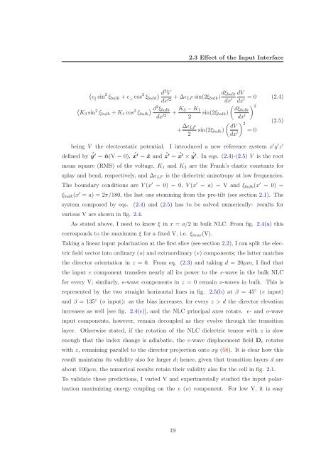
ǫ s<strong>in</strong> 2 ξbulk + ǫ⊥ cos 2 d<br />
ξbulk<br />
2V 2.3 Effect of the Input Interface<br />
dx ′2 + ∆ǫLF s<strong>in</strong>(2ξbulk) dξbulk<br />
dx ′ dx<br />
2 dξbulk<br />
<br />
K3 s<strong>in</strong> 2 ξbulk + K1 cos 2 d<br />
ξbulk<br />
2ξbulk dx ′2 + K3 − K1<br />
s<strong>in</strong>(2ξbulk)<br />
2<br />
+ ∆ǫLF<br />
2<br />
<br />
dV<br />
s<strong>in</strong>(2ξbulk)<br />
dx ′<br />
dV<br />
= 0 (2.4)<br />
′<br />
dx ′<br />
2<br />
= 0<br />
(2.5)<br />
be<strong>in</strong>g V the electrostatic potential. I <strong>in</strong>troduced a new reference system x ′ y ′ z ′<br />
def<strong>in</strong>ed by ˆ y ′ = ˆn(V = 0), ˆ x ′ = ˆx and ˆ z ′ = ˆ x ′ × ˆ y ′ . In eqs. (2.4)-(2.5) V is the root<br />
mean square (RMS) of the voltage, K1 and K3 are the Frank’s elastic constants for<br />
splay and bend, respectively, and ∆ǫLF is the dielectric anisotropy at low frequencies.<br />
The boundary conditions are V (x ′ = 0) = 0, V (x ′ = a) = V and ξbulk(x ′ = 0) =<br />
ξbulk(x ′ = a) = 2π/180, the last one stemm<strong>in</strong>g from the pre-tilt (see section 2.1). The<br />
system composed by eqs. (2.4) and (2.5) has to be solved numerically: results for<br />
various V are shown <strong>in</strong> fig. 2.4.<br />
As stated above, I need to know ξ <strong>in</strong> x = a/2 <strong>in</strong> bulk NLC. From fig. 2.4(a) this<br />
corresponds to the maximum ξ for a fixed V, i.e. ξmax(V).<br />
Tak<strong>in</strong>g a l<strong>in</strong>ear <strong>in</strong>put polarization at the first slice (see section 2.2), I can split the elec-<br />
tric field vector <strong>in</strong>to ord<strong>in</strong>ary (o) and extraord<strong>in</strong>ary (e) components; the latter matches<br />
the director orientation <strong>in</strong> z = 0. From eq. (2.3) and tak<strong>in</strong>g d = 20µm, I f<strong>in</strong>d that<br />
the <strong>in</strong>put e component transfers nearly all its power to the e-wave <strong>in</strong> the bulk NLC<br />
for every V; similarly, o-wave components <strong>in</strong> z = 0 rema<strong>in</strong> o-waves <strong>in</strong> bulk. This is<br />
represented by the two straight horizontal l<strong>in</strong>es <strong>in</strong> fig. 2.5(b) at β = 45 ◦ (e <strong>in</strong>put)<br />
and β = 135 ◦ (o <strong>in</strong>put): as the bias <strong>in</strong>creases, for every z > d the director elevation<br />
<strong>in</strong>creases as well [see fig. 2.4(c)], and the NLC pr<strong>in</strong>cipal axes rotate. e- and o-wave<br />
<strong>in</strong>put components, however, rema<strong>in</strong> decoupled as they evolve through the transition<br />
layer. Otherwise stated, if the rotation of the NLC dielectric tensor with z is slow<br />
enough that the <strong>in</strong>dex change is adiabatic, the e-wave displacement field De rotates<br />
with z, rema<strong>in</strong><strong>in</strong>g parallel to the director projection onto xy (58). It is clear how this<br />
result ma<strong>in</strong>ta<strong>in</strong>s its validity also for larger d; hence, given that transition layers d are<br />
about 100µm, the numerical results reta<strong>in</strong> their validity also for the cell <strong>in</strong> fig. 2.1.<br />
To validate these predictions, I varied V and experimentally studied the <strong>in</strong>put polar-<br />
ization maximiz<strong>in</strong>g energy coupl<strong>in</strong>g on the e (o) component. For low V, it is easy<br />
19


