Solitons in Nonlocal Media
Solitons in Nonlocal Media
Solitons in Nonlocal Media

Create successful ePaper yourself
Turn your PDF publications into a flip-book with our unique Google optimized e-Paper software.
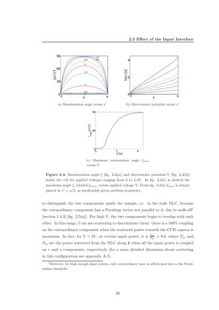
(a) Reorientation angle versus x ′<br />
(c) Maximum reorientation angle ξmax<br />
versus V<br />
2.3 Effect of the Input Interface<br />
(b) Electrostatic potential versus x ′<br />
Figure 2.4: Reorientation angle ξ [fig. 2.4(a)] and electrostatic potential V [fig. 2.4(b)]<br />
<strong>in</strong>side the cell for applied voltages rang<strong>in</strong>g from 0 to 4.5V . In fig. 2.4(c) is plotted the<br />
maximum angle ξ, labeled ξmax, versus applied voltage V. From fig. 2.4(a) ξmax is always<br />
placed <strong>in</strong> x ′ = a/2, as predictable given problem symmetry.<br />
to dist<strong>in</strong>guish the two components <strong>in</strong>side the sample, i.e. <strong>in</strong> the bulk NLC, because<br />
the extraord<strong>in</strong>ary component has a Poynt<strong>in</strong>g vector not parallel to ˆz, due to walk-off 1<br />
[section 1.4.3] [fig. 2.5(a)]. For high V, the two components beg<strong>in</strong> to overlap with each<br />
other. In this range, I can use scatter<strong>in</strong>g to discrim<strong>in</strong>ate them: there is a 100% coupl<strong>in</strong>g<br />
on the extraord<strong>in</strong>ary component when the scattered power towards the CCD camera is<br />
maximum. In fact, for V > 2V , at certa<strong>in</strong> <strong>in</strong>put power, it is Pse<br />
Pso > 9.6, where Pse and<br />
Pso are the power scattered from the NLC along ˆx when all the <strong>in</strong>put power is coupled<br />
on e and o components, respectively [for a more detailed discussion about scatter<strong>in</strong>g<br />
<strong>in</strong> this configuration see appendix A.1].<br />
1 Moreover, for high enough <strong>in</strong>put powers, only extraord<strong>in</strong>ary wave is self-focused due to the Freed-<br />
ericksz threshold.<br />
20