24-Bit, 192-kHz Sampling, Advanced Segment, Audio Stereo DAC ...
24-Bit, 192-kHz Sampling, Advanced Segment, Audio Stereo DAC ...
24-Bit, 192-kHz Sampling, Advanced Segment, Audio Stereo DAC ...

Create successful ePaper yourself
Turn your PDF publications into a flip-book with our unique Google optimized e-Paper software.
www.ti.com<br />
<br />
SLES105B − FEBRUARY 2004 − REVISED NOVEMBER 2006<br />
ZFGx: Zero-Detection Flag<br />
Where x = L or R, corresponding to the <strong>DAC</strong> output channel. These bits are available only for readback.<br />
Default value: 00<br />
ZFGx = 0 Not zero<br />
ZFGx = 1 Zero detected<br />
These bits show zero conditions. Their status is the same as that of the zero flags at ZEROL (pin 1) and ZEROR (pin 2).<br />
See Zero Detect in the FUNCTION DESCRIPTIONS section.<br />
B15 B14 B13 B12 B11 B10 B9 B8 B7 B6 B5 B4 B3 B2 B1 B0<br />
Register 23 R 0 0 1 0 1 1 1 RSV RSV RSV ID4 ID3 ID2 ID1 ID0<br />
R: Read Mode Select<br />
Value is always 1, specifying the readback mode.<br />
ID[4:0]: Device ID<br />
The ID[4:0] bits hold a device ID in the TDMCA mode.<br />
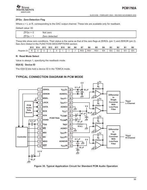
TYPICAL CONNECTION DIAGRAM IN PCM MODE<br />
Controller<br />
PCM<br />
<strong>Audio</strong><br />
Data<br />
Source<br />
0.1 µF<br />
+<br />
10 µF<br />
1<br />
2<br />
3<br />
4<br />
5<br />
6<br />
7<br />
8<br />
9<br />
10<br />
11<br />
12<br />
13<br />
14<br />
3.3 V<br />
ZEROL<br />
ZEROR<br />
MSEL<br />
LRCK<br />
DATA AGND2 <strong>24</strong><br />
BCK<br />
SCK<br />
VCOML<br />
PCM1792A<br />
DGND<br />
VCOMR<br />
VDD<br />
MS<br />
MDI<br />
MC<br />
MDO<br />
RST<br />
VCC2L<br />
AGND3L<br />
IOUTL−<br />
IOUTL+<br />
VCC1<br />
IREF<br />
AGND1<br />
IOUTR−<br />
IOUTR+<br />
AGND3R<br />
VCC2R<br />
28<br />
27<br />
26<br />
25<br />
23<br />
22<br />
21<br />
20<br />
19<br />
18<br />
17<br />
16<br />
15<br />
0.1 µF<br />
+<br />
5 V<br />
+<br />
47 µF<br />
10 kΩ<br />
0.1 µF<br />
+<br />
47 µF<br />
10 µF<br />
10 µF<br />
5 V<br />
10 µF<br />
−<br />
+<br />
−<br />
+<br />
−<br />
+<br />
−<br />
+<br />
Rf<br />
Rf<br />
Rf<br />
Rf<br />
Cf<br />
Cf<br />
Cf<br />
Cf<br />
Differential<br />
to<br />
Single<br />
Converter<br />
With<br />
Low-Pass<br />
Filter<br />
Differential<br />
to<br />
Single<br />
Converter<br />
With<br />
Low-Pass<br />
Filter<br />
Figure 35. Typical Application Circuit for Standard PCM <strong>Audio</strong> Operation<br />
+<br />
+<br />
5 V<br />
VOUT<br />
L-Channel<br />
VOUT<br />
R-Channel<br />
33