24-Bit, 192-kHz Sampling, Advanced Segment, Audio Stereo DAC ...
24-Bit, 192-kHz Sampling, Advanced Segment, Audio Stereo DAC ...
24-Bit, 192-kHz Sampling, Advanced Segment, Audio Stereo DAC ...

You also want an ePaper? Increase the reach of your titles
YUMPU automatically turns print PDFs into web optimized ePapers that Google loves.
SLES105B − FEBRUARY 2004 − REVISED NOVEMBER 2006<br />
56<br />
www.ti.com<br />
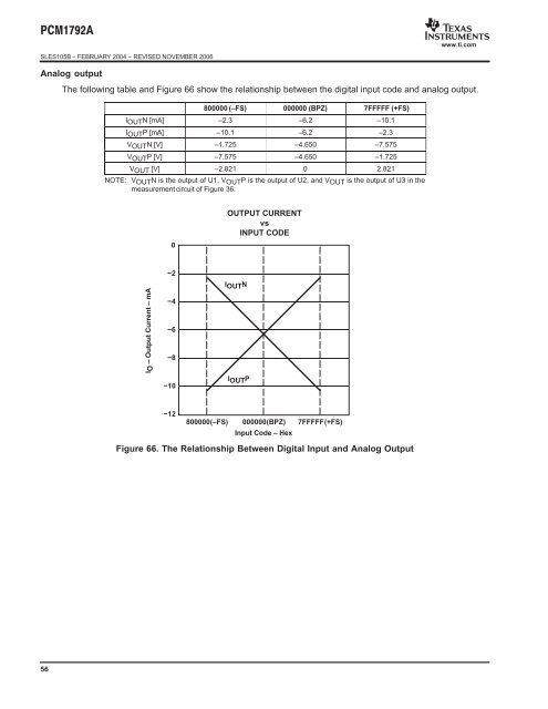
Analog output<br />
The following table and Figure 66 show the relationship between the digital input code and analog output.<br />
800000 (–FS) 000000 (BPZ) 7FFFFF (+FS)<br />
IOUTN [mA] –2.3 –6.2 –10.1<br />
IOUTP [mA] –10.1 –6.2 –2.3<br />
VOUTN [V] –1.725 –4.650 –7.575<br />
VOUTP [V] –7.575 –4.650 –1.725<br />
VOUT [V] –2.821 0 2.821<br />
NOTE: VOUTN is the output of U1, VOUTP is the output of U2, and VOUT is the output of U3 in the<br />
measurement circuit of Figure 36.<br />
IO – Output Current – mA<br />
0<br />
−2<br />
−4<br />
−6<br />
−8<br />
−10<br />
−12<br />
OUTPUT CURRENT<br />
vs<br />
INPUT CODE<br />
IOUTN<br />
IOUTP<br />
800000(–FS) 000000(BPZ) 7FFFFF(+FS)<br />
Input Code – Hex<br />
Figure 66. The Relationship Between Digital Input and Analog Output