24-Bit, 192-kHz Sampling, Advanced Segment, Audio Stereo DAC ...
24-Bit, 192-kHz Sampling, Advanced Segment, Audio Stereo DAC ...
24-Bit, 192-kHz Sampling, Advanced Segment, Audio Stereo DAC ...

Create successful ePaper yourself
Turn your PDF publications into a flip-book with our unique Google optimized e-Paper software.
www.ti.com<br />
<br />
SLES105B − FEBRUARY 2004 − REVISED NOVEMBER 2006<br />
<strong>Audio</strong> Fields<br />
The audio field is 32 bits in length and the audio data is transferred MSB first, so the other fields must be stuffed<br />
with 0s as shown in the following example.<br />
31 16 12 8 7 4 3 0<br />
audio data MSB <strong>24</strong> bits LSB All 0s<br />
TDMCA Register Requirements<br />
TDMCA mode requires device ID and audio channel information, previously described. The OPE bit in register<br />
19 indicates audio channel availability and register 23 indicates the device ID. Register 23 is used only in the<br />
TDMCA mode. See the mode control register map (Table 4).<br />
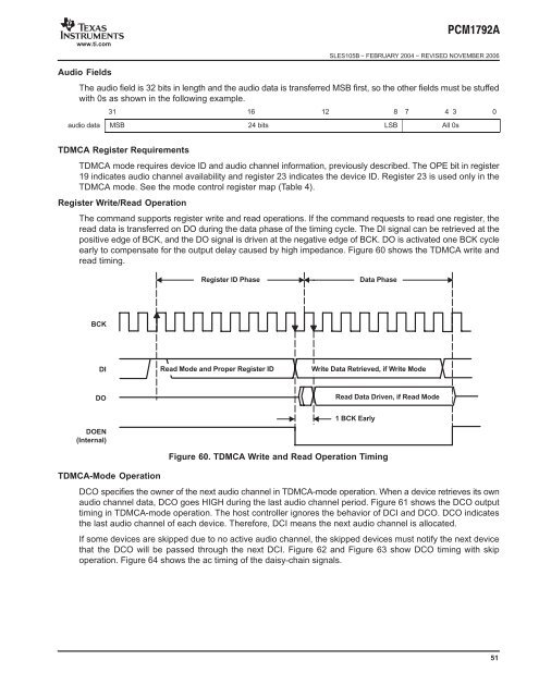
Register Write/Read Operation<br />
The command supports register write and read operations. If the command requests to read one register, the<br />
read data is transferred on DO during the data phase of the timing cycle. The DI signal can be retrieved at the<br />
positive edge of BCK, and the DO signal is driven at the negative edge of BCK. DO is activated one BCK cycle<br />
early to compensate for the output delay caused by high impedance. Figure 60 shows the TDMCA write and<br />
read timing.<br />
BCK<br />
DI<br />
DO<br />
DOEN<br />
(Internal)<br />
Register ID Phase Data Phase<br />
Read Mode and Proper Register ID<br />
Write Data Retrieved, if Write Mode<br />
Read Data Driven, if Read Mode<br />
1 BCK Early<br />
Figure 60. TDMCA Write and Read Operation Timing<br />
TDMCA-Mode Operation<br />
DCO specifies the owner of the next audio channel in TDMCA-mode operation. When a device retrieves its own<br />
audio channel data, DCO goes HIGH during the last audio channel period. Figure 61 shows the DCO output<br />
timing in TDMCA-mode operation. The host controller ignores the behavior of DCI and DCO. DCO indicates<br />
the last audio channel of each device. Therefore, DCI means the next audio channel is allocated.<br />
If some devices are skipped due to no active audio channel, the skipped devices must notify the next device<br />
that the DCO will be passed through the next DCI. Figure 62 and Figure 63 show DCO timing with skip<br />
operation. Figure 64 shows the ac timing of the daisy-chain signals.<br />
51