

simoreg 6ra70 dc master
simoreg 6ra70 dc master
simoreg 6ra70 dc master

Create successful ePaper yourself
Turn your PDF publications into a flip-book with our unique Google optimized e-Paper software.
2<br />
SIMOREG 6RA70 DC MASTER<br />
System Overview<br />
Open-loop and closed-loop control section<br />
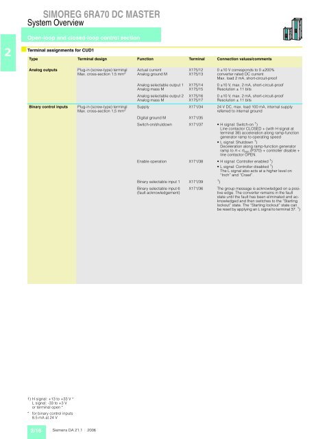
■ Terminal assignments for CUD1<br />
Type Terminal design Function Terminal Connection values/comments<br />
Analog outputs Plug-in (screw-type) terminal<br />
Max. cross-section 1.5 mm 2<br />
Binary control inputs Plug-in (screw-type) terminal<br />
Max. cross-section 1,5 mm 2<br />
1) H signal: +13 to +33 V *<br />
L signal: -33 to +3 V<br />
or terminal open *<br />
* for binary control inputs<br />
8.5 mA at 24 V<br />
2/16<br />
Siemens DA 21.1 · 2006<br />
Actual current<br />
Analog ground M<br />
Analog selectable output 1<br />
Analog mass M<br />
Analog selectable output 2<br />
Analog mass M<br />
X175/12<br />
X175/13<br />
X175/14<br />
X175/15<br />
X175/16<br />
X175/17<br />
0 ±10 V corresponds to 0 ±200%<br />
converter rated DC current<br />
Max. load 2 mA, short-circuit-proof<br />
0 ±10 V, max. 2 mA, short-circuit-proof<br />
Resolution ± 11 bits<br />
0 ±10 V, max. 2 mA, short-circuit-proof<br />
Resolution ± 11 bits<br />
Supply X171/34 24 V DC, max. load 100 mA, internal supply<br />
referred to internal ground<br />
Digital ground M X171/35<br />
Switch-on/shutdown X171/37 H signal: Switch-on 1 )<br />
Line contactor CLOSED + (with H signal at<br />
terminal 38) acceleration along ramp-function<br />
generator ramp to operating speed<br />
L signal: Shutdown 1 )<br />
Deceleration along ramp-function generator<br />
ramp to n < nmin (P370) + controller disable +<br />
line contactor OPEN.<br />
Enable operation X171/38 H signal: Controller enabled 1 )<br />
L signal: Controller disabled 1 )<br />
The L signal also acts at a higher level on<br />
“Inch” and “Crawl”.<br />
Binary selectable input 1 X171/39 1 )<br />
Binary selectable input 6<br />
(fault acknowledgement)<br />
X171/36 The group message is acknowledged on a positive<br />
edge. The converter remains in the fault<br />
state until the fault has been eliminated and acknowledged<br />
and then switches to the “Starting<br />
lockout” state. The “Starting lockout” state can<br />
be reset by applying an L signal to terminal 37. 1 )


