

simoreg 6ra70 dc master
simoreg 6ra70 dc master
simoreg 6ra70 dc master

Create successful ePaper yourself
Turn your PDF publications into a flip-book with our unique Google optimized e-Paper software.
4<br />
SIMOREG 6RA70 DC MASTER<br />
Options<br />
Communication<br />
■ SIMOLINK communication board SLB<br />
The SLB optional board<br />
(SIMOLINK Board) acts as the<br />
interface between SIMOREG<br />
drives and the SIMOLINK system.<br />
The SLB is mounted on the ADB<br />
adapter board. An LBA bus<br />
adapter is needed for this purpose.<br />
Every SLB optional board is a<br />
node in the SIMOLINK system.<br />
The maximum number of nodes<br />
is restricted to 201.<br />
The SIMOLINK drive interface is<br />
used to exchange data rapidly<br />
between different drives and to<br />
synchronize them with a common<br />
system clock cycle.<br />
SIMOLINK is a closed circuit<br />
into which all nodes are connected.<br />
Data are exchanged between<br />
the individual nodes by way of<br />
fiber-optic cables. Optical<br />
fibers made of glass or plastic<br />
can be used as transmission<br />
lines.<br />
The SLB optional board has a<br />
24 V voltage input for connecting<br />
an external voltage supply.<br />
This ensures that data can still<br />
be exchanged within the<br />
SIMOLINK circuit when the<br />
converter is switched off.<br />
The board features three LEDs<br />
for displaying the current operational<br />
status.<br />
Operating principle<br />
The SLB optional board acts<br />
as the interface between the<br />
SIMOLINK system and converters<br />
and/or inverters. It can operate<br />
as either a SIMOLINK<br />
Dispatcher or a SIMOLINK<br />
Transceiver. Its functionality is<br />
selected by means of parameter<br />
settings.<br />
4/28<br />
Siemens DA 21.1 · 2006<br />
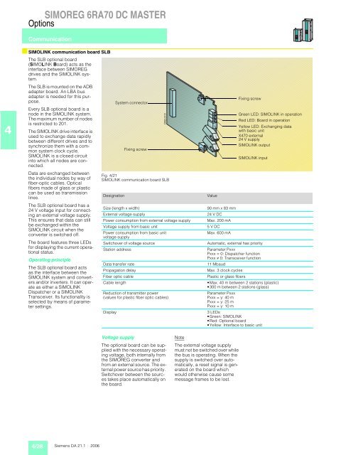
System connector<br />
Fixing screw<br />
Fig. 4/21<br />
SIMOLINK communication board SLB<br />
Designation Value<br />
Voltage supply<br />
The optional board can be supplied<br />
with the necessary operating<br />
voltage, both internally from<br />
the SIMOREG converter and<br />
from an external source. The external<br />
power source has priority.<br />
Switchover between the sources<br />
takes place automatically on<br />
the board.<br />
DA65-5101<br />
Note<br />
The external voltage supply<br />
must not be switched over while<br />
the bus is operating. When the<br />
supply is switched over automatically,<br />
a reset signal is generated<br />
on the board which<br />
would otherwise cause some<br />
message frames to be lost.<br />
Fixing screw<br />
Green LED: SIMOLINK in operation<br />
Red LED: Board in operation<br />
Yellow LED: Exchanging data<br />
with basic unit<br />
X470 external<br />
24 V supply<br />
SIMOLINK output<br />
SIMOLINK input<br />
Size (length x width) 90 mm x 83 mm<br />
External voltage supply 24 V DC<br />
Power consumption from external voltage supply Max. 200 mA<br />
Voltage supply from basic unit 5 V DC<br />
Power consumption from basic unit<br />
voltage supply<br />
Max. 600 mA<br />
Switchover of voltage source Automatic, external has priority<br />
Station address Parameter Pxxx<br />
Pxxx = 0: Dispatcher function<br />
Pxxx ž 0: Transceiver function<br />
Data transfer rate 11 Mbaud<br />
Propagation delay Max. 3 clock cycles<br />
Fiber optic cable Plastic or glass fibers<br />
Cable length Max. 40 m between 2 stations (plastic)<br />
300 m between 2 stations (glass)<br />
Reduction of transmitter power<br />
Parameter Pxxx<br />
(values for plastic fiber optic cables)<br />
Pxxx = y: 40 m<br />
Pxxx = y: 25 m<br />
Pxxx = y: 10 m<br />
Display 3 LEDs<br />
Green: SIMOLINK<br />
Red: Optional board<br />
Yellow: Interface to basic unit


