

simoreg 6ra70 dc master
simoreg 6ra70 dc master
simoreg 6ra70 dc master

You also want an ePaper? Increase the reach of your titles
YUMPU automatically turns print PDFs into web optimized ePapers that Google loves.
4<br />
SIMOREG 6RA70 DC MASTER<br />
Options<br />
Operating and monitoring<br />
■ OP1S operator panel<br />
The OP1S (Operator Panel) is<br />
an optional input/output unit that<br />
can be used to parameterize<br />
the converters. Parameterization<br />
is menu driven; the parameter<br />
number is selected and the<br />
parameter value is entered. The<br />
displays are in plain text.<br />
The descriptions of the parameters<br />
and parameter values as<br />
well as the text displays are included<br />
in English, German,<br />
French, Spanish and Italian as<br />
standard.<br />
The OP1S is equipped with nonvolatile<br />
memory and is able to<br />
save complete parameter sets<br />
permanently. It can therefore be<br />
used to archive parameter settings<br />
and to transfer parameter<br />
sets from one unit to another.<br />
The memory capacity is sufficient<br />
to store, for example, 5<br />
data sets from CUMC boards. It<br />
is not possible to save data sets<br />
from technology boards<br />
(e.g. T100, T300).<br />
There is a 9-pin Sub-D connector<br />
on the rear of the OP1S. This<br />
is used for connection of the<br />
power supply as well as for<br />
communication with the connected<br />
units.<br />
The OP1S operator panel is directly<br />
plugged into the Sub-D<br />
socket of the PMU operator control<br />
and parameterization panel<br />
and screwed into the front cover.<br />
The OP1S operator panel<br />
can also be used as a remote<br />
operation device. The cable between<br />
the PMU and the OP1S<br />
can be up to 200 m in length.<br />
In the case of distances greater<br />
than 5 m, a generally available<br />
5 V power supply unit with a<br />
current of at least 400 mA<br />
(Fig. 4/33) must be connected<br />
at the OP1S end.<br />
4/36<br />
Siemens DA 21.1 · 2006<br />
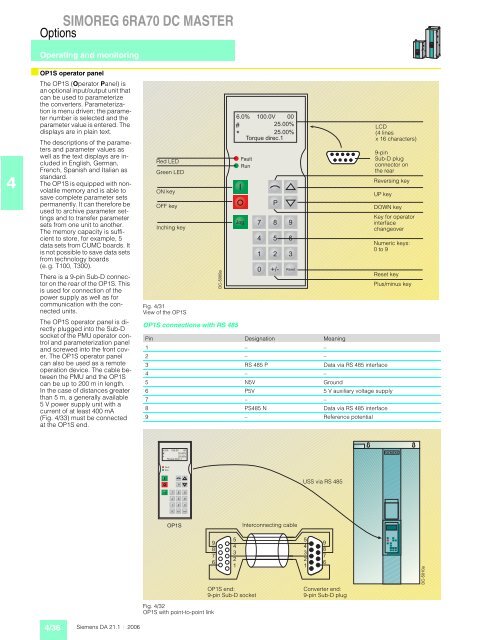
Red LED<br />
Green LED<br />
ON key<br />
OFF key<br />
Inching key<br />
Fig. 4/31<br />
View of the OP1S<br />
DC-5009a<br />
OP1S connections with RS 485<br />
6.0% 100.0V 00<br />
#<br />
25.00%<br />
*<br />
25.00%<br />
Torque direc.1<br />
Fault<br />
Run<br />
Jog<br />
P<br />
7 8 9<br />
4 5 6<br />
1 2 3<br />
0 +/ - Reset<br />
LCD<br />
(4 lines<br />
x 16 characters)<br />
9-pin<br />
Sub-D plug<br />
connector on<br />
the rear<br />
Reversing key<br />
UP key<br />
DOWN key<br />
Key for operator<br />
interface<br />
changeover<br />
Numeric keys:<br />
0 to 9<br />
Reset key<br />
Plus/minus key<br />
Pin Designation Meaning<br />
1 – –<br />
2 – –<br />
3 RS 485 P Data via RS 485 interface<br />
4 – –<br />
5 N5V Ground<br />
6 P5V 5 V auxiliary voltage supply<br />
7 – –<br />
8 PS485 N Data via RS 485 interface<br />
9 – Reference potential<br />
6.0% 100.0V 00<br />
#<br />
25.00%<br />
*<br />
25.00%<br />
Torque direc.1<br />
Fault<br />
Run<br />
Jog<br />
P<br />
7 8 9<br />
4 5 6<br />
1 2 3<br />
0 +/ - Reset<br />
OP1S<br />
9<br />
8<br />
7<br />
6<br />
Fig. 4/32<br />
OP1S with point-to-point link<br />
5<br />
4<br />
3<br />
2<br />
1<br />
OP1S end:<br />
9-pin Sub-D socket<br />
Interconnecting cable<br />
USS via RS 485<br />
5<br />
4<br />
3<br />
2<br />
1<br />
9<br />
8<br />
7<br />
6<br />
Converter end:<br />
9-pin Sub-D plug<br />
DC-5010a


