

simoreg 6ra70 dc master
simoreg 6ra70 dc master
simoreg 6ra70 dc master

Create successful ePaper yourself
Turn your PDF publications into a flip-book with our unique Google optimized e-Paper software.
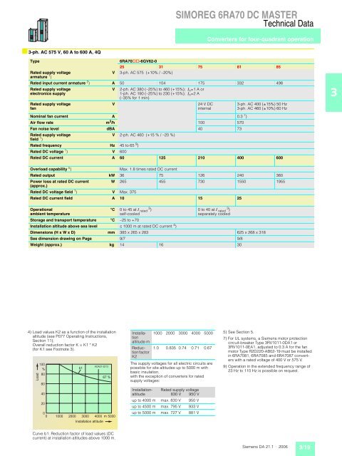
■ 3-ph. AC 575 V, 60 A to 600 A, 4Q<br />
SIMOREG 6RA70 DC MASTER<br />
Technical Data<br />
Type 6RA70@@-6GV62-0<br />
25 31 75 81 85<br />
Rated supply voltage<br />
armature 1 )<br />
V 3-ph. AC 575 (+10% / –20%)<br />
Rated input current armature 2 ) A 50 104 175 332 498<br />
Rated supply voltage<br />
electronics supply<br />
Rated supply voltage<br />
fan<br />
V 2-ph. AC 380 (–25%) to 460 (+15%); , n =1 A or<br />
1-ph. AC 190 (–25%) to 230 (+15%); , n =2 A<br />
(–35% for 1 min)<br />
V 24 V DC<br />
internal<br />
3-ph. AC 400 (±15%) 50 Hz<br />
3-ph. AC 460 (±10%) 60 Hz<br />
Nominal fan current A 0.3 7 )<br />
Air flow rate m3 /h 100 570<br />
Fan noise level dBA 40 73<br />
Rated supply voltage<br />
field 1 )<br />
V 2-ph. AC 460 (+15 % / –20 %)<br />
Rated frequency Hz 45 to 65 9 )<br />
Rated DC voltage 1 ) V 600<br />
Rated DC current A 60 125 210 400 600<br />
Overload capability 5 ) Max. 1.8 times rated DC current<br />
Rated output kW 36 75 126 240 360<br />
Power loss at rated DC current<br />
(approx.)<br />
W 265 455 730 1550 1955<br />
Rated DC voltage field 1 ) V Max. 375<br />
Rated DC current field A 10 15 25<br />
Operational<br />
ambient temperature<br />
°C 0 to 45 at , rated 3 )<br />
self-cooled<br />
Converters for four-quadrant operation<br />
0 to 40 at , rated 3 )<br />
separately cooled<br />
Storage and transport temperature °C –25 to +70<br />
Installation altitude above sea level ˆ 1000 m at rated DC current 4 )<br />
Dimensions (H x W x D) mm 385 x 265 x 283 625 x 268 x 318<br />
See dimension drawing on Page 9/7 9/8<br />
Weight (approx.) kg 14 16 30<br />
4) Load values K2 as a function of the installation<br />
altitude (see P077 Operating Instructions,<br />
Section 11);<br />
Overall reduction factor K = K1 * K2<br />
(for K1 see Footnote 3).<br />
<br />
<br />
<br />
<br />
<br />
<br />
<br />
<br />
<br />
<br />
<br />
<br />
Curve b1: Reduction factor of load values (DC<br />
current) at installation altitudes above 1000 m.<br />
<br />
<br />
Installation<br />
altitude m<br />
Reduction<br />
factor<br />
K2<br />
1000 2000 3000 4000 5000<br />
The supply voltages for all electric circuits are<br />
possible for site altitudes up to 5000 m with<br />
basic insulation,<br />
with the exception of converters for rated<br />
supply voltages:<br />
Installationaltitude<br />
1.0 0.835 0.74 0.71 0.67<br />
Rated supply voltage<br />
830 V 950 V<br />
up to 4000 m max. 830 V 950 V<br />
up to 4500 m max. 795 V 933 V<br />
up to 5000 m max. 727 V 881 V<br />
5) See Section 5.<br />
7) For UL systems, a Siemens motor protection<br />
circuit-breaker Type 3RV1011-0DA1 or<br />
3RV1011-0EA1, adjusted to 0.3 A for the fan<br />
motor Type R2D220-AB02-19 must be installed<br />
in 6RA7081, 6RA7085 and 6RA7087 converters<br />
with a rated voltage of 400 V or 575 V.<br />
9) Operation in the extended frequency range of<br />
23 Hz to 110 Hz is possible on request.<br />
Siemens DA 21.1 · 2006 3/19<br />
3


