

simoreg 6ra70 dc master
simoreg 6ra70 dc master
simoreg 6ra70 dc master

You also want an ePaper? Increase the reach of your titles
YUMPU automatically turns print PDFs into web optimized ePapers that Google loves.
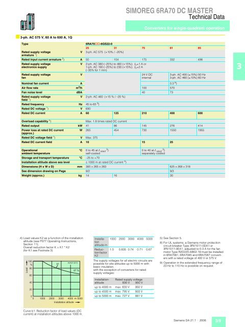
■ 3-ph. AC 575 V, 60 A to 600 A, 1Q<br />
SIMOREG 6RA70 DC MASTER<br />
Technical Data<br />
Converters for single-quadrant operation<br />
Type 6RA70@@-6GS22-0<br />
25 31 75 81 85<br />
Rated supply voltage<br />
armature 1 )<br />
V 3-ph. AC 575 (+10% / –20%)<br />
Rated input current armature 2 ) A 50 104 175 332 498<br />
Rated supply voltage<br />
electronics supply<br />
Rated supply voltage<br />
fan<br />
V 2-ph. AC 380 (–25%) to 460 (+15%); , n =1 A or<br />
1-ph. AC 190 (–25%) to 230 (+15%); , n =2 A<br />
(–35% for 1 min)<br />
V 24 V DC<br />
internal<br />
3-ph. AC 400 (±15%) 50 Hz<br />
3-ph. AC 460 (±10%) 60 Hz<br />
Nominal fan current A 0.3 8 )<br />
Air flow rate m3 /h 100 570<br />
Fan noise level dBA 40 73<br />
Rated supply voltage<br />
field 1 )<br />
V 2-ph. AC 460 (+15 % / –20 %)<br />
Rated frequency Hz 45 to 65 9 )<br />
Rated DC voltage 1 ) V 690<br />
Rated DC current A 60 125 210 400 600<br />
Overload capability 5 ) Max. 1.8 times rated DC current<br />
Rated output kW 41 86 145 276 414<br />
Power loss at rated DC current<br />
(approx.)<br />
W 265 454 730 1550 1955<br />
Rated DC voltage field 1 ) V Max. 375<br />
Rated DC current field A 10 15 25<br />
Operational<br />
ambient temperature<br />
°C 0 to 45 at , rated 3 )<br />
self-cooled<br />
0 to 40 at , rated 3 )<br />
separately cooled<br />
Storage and transport temperature °C –25 to +70<br />
Installation altitude above sea level ˆ 1000 m at rated DC current 4 )<br />
Dimensions (H x W x D) mm 385 x 265 x 283 625 x 268 x 318<br />
See dimension drawing on Page 9/2 9/3<br />
Weight (approx.) kg 14 16 30<br />
4) Load values K2 as a function of the installation<br />
altitude (see P077 Operating Instructions,<br />
Section 11);<br />
Overall reduction factor K = K1 * K2<br />
(for K1 see Footnote 3)<br />
<br />
<br />
<br />
<br />
<br />
<br />
<br />
<br />
<br />
<br />
<br />
<br />
Curve b1: Reduction factor of load values (DC<br />
current) at installation altitudes above 1000 m.<br />
<br />
<br />
Installation<br />
altitude m<br />
Reduction<br />
factor<br />
K2<br />
1000 2000 3000 4000 5000<br />
The supply voltages for all electric circuits are<br />
possible for site altitudes up to 5000 m with<br />
basic insulation,<br />
with the exception of converters for rated<br />
supply voltages:<br />
Installationaltitude<br />
1.0 0.835 0.74 0.71 0.67<br />
Rated supply voltage<br />
830 V 950 V<br />
up to 4000 m max. 830 V 950 V<br />
up to 4500 m max. 795 V 933 V<br />
up to 5000 m max. 727 V 881 V<br />
5) See Section 5.<br />
8) For UL systems, a Siemens motor protection<br />
circuit-breaker Type 3RV1011-0DA1 or<br />
3RV1011-0EA1, adjusted to 0.3 A for the fan<br />
motor Type R2D220-AB02-19 must be installed<br />
in 6RA7081, 6RA7085 and 6RA7087 converters<br />
with a rated voltage of 400 V or 575 V.<br />
9) Operation in the extended frequency range of<br />
23 Hz to 110 Hz is possible on request.<br />
Siemens DA 21.1 · 2006 3/9<br />
3


