

simoreg 6ra70 dc master
simoreg 6ra70 dc master
simoreg 6ra70 dc master

Create successful ePaper yourself
Turn your PDF publications into a flip-book with our unique Google optimized e-Paper software.
SIMOREG 6RA70 DC MASTER<br />
Options<br />
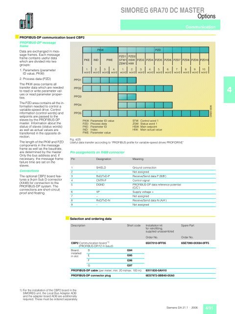
■ PROFIBUS-DP communication board CBP2<br />
PROFIBUS-DP message<br />
frame<br />
Data are exchanged in mes-<br />
PKW PZD<br />
sage frames. Each message<br />
frame contains useful data<br />
which are divided into two<br />
groups:<br />
PKE IND PWE<br />
PZD1<br />
STW1<br />
ZSW1<br />
PZD2<br />
HSW PZD3<br />
HIW<br />
PZD4 PZD5 PZD6 PZD7 PZD8 PZD9 PZD10<br />
1. Parameters (parameter<br />
ID value, PKW)<br />
1.<br />
word<br />
2.<br />
word<br />
3.<br />
word<br />
4.<br />
word<br />
1.<br />
word<br />
2.<br />
word<br />
3.<br />
word<br />
4.<br />
word<br />
5.<br />
word<br />
6.<br />
word<br />
7.<br />
word<br />
8.<br />
word<br />
9.<br />
word<br />
10.<br />
word<br />
2. Process data (PZD)<br />
The PKW area contains all<br />
PPO1<br />
transfer data which are needed<br />
to read or write parameter val-<br />
PPO2<br />
ues or read parameter properties.<br />
PPO3<br />
The PZD area contains all the information<br />
needed to control a<br />
variable-speed drive. Control<br />
PPO4<br />
information (control words) and<br />
setpoints are passed to the<br />
PPO5<br />
slaves by the PROFIBUS-DP<br />
<strong>master</strong>. Information about the<br />
status of slaves (status words)<br />
PKW: Parameter ID value<br />
PZD: Process data<br />
PKE: Parameter ID<br />
STW: Control word 1<br />
ZSW: Status word 1<br />
HSW: Main setpoint<br />
as well as actual values are<br />
IND: Index<br />
HIW: Main actual value<br />
transferred in the opposite direction.<br />
PWE: Parameter value<br />
The length of the PKW and PZD<br />
components in the message<br />
frame as well as the baudrate,<br />
Fig. 4/25<br />
Useful data transfer according to “PROFIBUS profile for variable-speed drives PROFIDRIVE”<br />
are determined by the <strong>master</strong>.<br />
Only the bus address and, if<br />
Pin assignments on X488 connector<br />
necessary, the message frame<br />
failure time are set on the<br />
Pin Designation Meaning<br />
slaves.<br />
1 SHIELD Ground connection<br />
Connections<br />
2 – Not assigned<br />
The optional CBP2 board fea- 3 RxD/TxD-P Receive/Send data P (B/B’)<br />
tures a 9-pin Sub D connector<br />
(X448) for connection to the<br />
PROFIBUS-DP system. The<br />
connections are short-circuit<br />
proof and floating.<br />
4<br />
5<br />
6<br />
CNTR-P<br />
DGND<br />
VP<br />
Control signal<br />
PROFIBUS-DP data reference potential<br />
(C/C’)<br />
Supply voltage +<br />
7 – Not assigned<br />
8 RxD/TxD-N Receive/Send data N (A/A’)<br />
9 – Not assigned<br />
1) For the installation of the CBP2 board in the<br />
SIMOREG unit, the Local Bus Adapter ADB<br />
and the adapter board ADB are additionally<br />
required. These must be ordered separately.<br />
■ Selection and ordering data<br />
Description Short code Installation kit<br />
for retrofitting,<br />
supplied unassembled<br />
Communication<br />
Spare Part<br />
Order No.<br />
Order No.<br />
CBP2 Communication board 1)<br />
(PROFIBUS-DP/12 m baud)<br />
6SX7010-0FF05 6SE7090-0XX84-0FF5<br />
Board, D G94<br />
installed<br />
in slot E G95<br />
F G96<br />
G G97<br />
PROFIBUS-DP cable (per meter; min. 20 m/max. 100 m) 6XV1830-0AH10<br />
PROFIBUS-DP connector plug 6ES7972-0BB40-0XA0<br />
DA65-5335<br />
Siemens DA 21.1 · 2006 4/31<br />
4


