

CUTSKILL® C-35A - Victor Technologies
CUTSKILL® C-35A - Victor Technologies
CUTSKILL® C-35A - Victor Technologies

You also want an ePaper? Increase the reach of your titles
YUMPU automatically turns print PDFs into web optimized ePapers that Google loves.
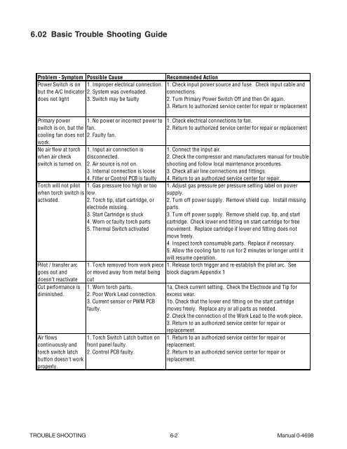
6.02 Basic Trouble Shooting Guide<br />
Problem - Symptom Possible Cause Recommended Action<br />
Power Switch is on<br />
but the A/C Indicator<br />
does not light<br />
Primary power<br />
switch is on, but the<br />
cooling fan does not<br />
work.<br />
No air flow at torch<br />
when air check<br />
switch is turned on.<br />
Torch will not pilot<br />
when torch switch is<br />
activated.<br />
Pilot / transfer arc<br />
goes out and<br />
doesn’t reactivate<br />
Cut performance is<br />
diminished.<br />
Air flows<br />
continuously and<br />
torch switch latch<br />
button doesn't work<br />
properly.<br />
1. Improper electrical connection.<br />
2. System was overloaded.<br />
3. Switch may be faulty<br />
1. No power or incorrect power to<br />
fan.<br />
2. Faulty fan.<br />
1. Input air connection is<br />
disconnected.<br />
2. Air source is not on.<br />
3. Internal connection is loose<br />
4. Filter or Control PCB is faulty<br />
1. Gas pressure too high or too<br />
low.<br />
2. Torch tip, start cartridge, or<br />
electrode missing.<br />
3. Start Cartridge is stuck<br />
4. Worn or faulty torch parts<br />
5. Thermal Switch activated<br />
1. Torch removed from work piece<br />
or moved away from metal being<br />
cut<br />
1. Worn torch parts.<br />
2. Poor Work Lead connection.<br />
3. Current sensor or PWM PCB<br />
faulty.<br />
1. Torch Switch Latch button on<br />
front panel faulty.<br />
2. Control PCB faulty.<br />
1. Check input power source and fuse. Check input cable and<br />
connections.<br />
2. Turn Primary Power Switch Off and then On again.<br />
3. Return to authorized service center for repair or replacement<br />
1. Check electrical connections to fan.<br />
2. Return to authorized service center for repair or replacement<br />
1. Connect the input air.<br />
2. Check the compressor and manufacturers manual for trouble<br />
shooting and follow local maintenance procedures.<br />
3. Check all air line connections and fittings.<br />
4. Return to an authorized service center for repair.<br />
1. Adjust gas pressure per pressure setting label on power<br />
supply.<br />
2. Turn off power supply. Remove shield cup. Install missing<br />
parts.<br />
3. Turn off power supply. Remove shield cup, tip, and start<br />
cartridge. Check lower end fitting on start cartridge for free<br />
movement. Replace cartridge if lower end fitting does not<br />
move freely.<br />
4. Inspect torch consumable parts. Replace if necessary.<br />
5. Allow the cooling fan to run for 2 minutes or longer until it<br />
will resume operation.<br />
1. Release torch trigger and re-establish the pilot arc. See<br />
block diagram Appendix 1<br />
1a. Check current setting. Check the Electrode and Tip for<br />
excess wear.<br />
1b. Check that the lower end fitting on the start cartridge<br />
moves freely. Replace any or all parts as needed.<br />
2. Check the connection of the Work Lead to the work piece.<br />
3. Return to an authorized service center for repair or<br />
replacement.<br />
1. Return to an authorized service center for repair or<br />
replacement.<br />
2. Return to an authorized service center for repair or<br />
replacement.<br />
TROUBLE SHOOTING 6-2 Manual 0-4698


