

Download Hardware Manual (PDF file) - esd electronics, Inc.
Download Hardware Manual (PDF file) - esd electronics, Inc.
Download Hardware Manual (PDF file) - esd electronics, Inc.

Create successful ePaper yourself
Turn your PDF publications into a flip-book with our unique Google optimized e-Paper software.
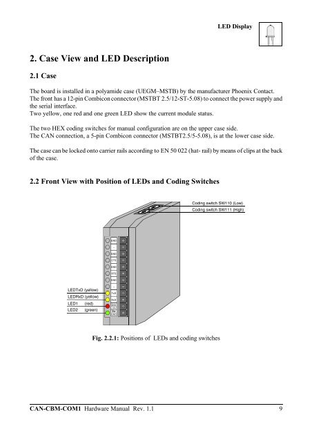
2. Case View and LED Description<br />
2.1 Case<br />
LEDRxD (yellow)<br />
LED1 (red)<br />
LED2 (green)<br />
GND<br />
-<br />
GND<br />
CTS<br />
GND<br />
RTS<br />
GND<br />
-<br />
TxD<br />
RxD<br />
Error<br />
+24V<br />
Stat<br />
GND<br />
LED Display<br />
The board is installed in a polyamide case (UEGM–MSTB) by the manufacturer Phoenix Contact.<br />
The front has a 12-pin Combicon connector (MSTBT 2.5/12-ST-5.08) to connect the power supply and<br />
the serial interface.<br />
Two yellow, one red and one green LED show the current module status.<br />
The two HEX coding switches for manual configuration are on the upper case side.<br />
The CAN connection, a 5-pin Combicon connector (MSTBT2.5/5-5.08), is at the lower case side.<br />
The case can be locked onto carrier rails according to EN 50 022 (hat- rail) by means of clips at the back<br />
of the case.<br />
2.2 Front View with Position of LEDs and Coding Switches<br />
LEDTxD (yellow)<br />
Coding switch SW110 (Low)<br />
Coding switch SW111 (High)<br />
Fig. 2.2.1: Positions of LEDs and coding switches<br />
CAN-CBM-COM1 <strong>Hardware</strong> <strong>Manual</strong> Rev. 1.1 9


