

Download Hardware Manual (PDF file) - esd electronics, Inc.
Download Hardware Manual (PDF file) - esd electronics, Inc.
Download Hardware Manual (PDF file) - esd electronics, Inc.

You also want an ePaper? Increase the reach of your titles
YUMPU automatically turns print PDFs into web optimized ePapers that Google loves.
CAN_H<br />
CAN_L<br />
CAN_GND<br />
Shielded wire with<br />
transposed wires<br />
120 Ohm<br />
DSUB9 connector<br />
(female or male)<br />
CAN_GND<br />
DSUB9 connector<br />
(female or male)<br />
pin designation<br />
(at wire shield)<br />
pin designation<br />
1<br />
2<br />
n.c.<br />
CAN_L<br />
n.c.<br />
1<br />
2<br />
3<br />
3<br />
4<br />
n.c.<br />
n.c.<br />
4<br />
5<br />
n.c.<br />
n.c.<br />
5<br />
6<br />
7<br />
n.c.<br />
CAN_H<br />
n.c.<br />
6<br />
7<br />
8<br />
n.c.<br />
n.c.<br />
8<br />
9<br />
n.c.<br />
n.c.<br />
9<br />
connector case n.c.<br />
n.c. connector case<br />
n.c. = not connected<br />
Wiring<br />
6. Correctly Wiring Electrically Isolated CAN Networks<br />
Generally all instructions applying for wiring regarding an electromagnetic compatible installation,<br />
wiring, cross sections of wires, material to be used, minimum distances, lightning protection, etc. have<br />
to be followed.<br />
The following general rules for the CAN wiring must be followed:<br />
1.<br />
2.<br />
3.<br />
A CAN net must not branch (exception: short dead-end feeders) and has to be terminated<br />
by the wave impedance of the wire (generally 120 Ω ±10%) at both ends (between the<br />
signals CAN_L and CAN_H and not at GND)!<br />
A CAN data wire requires two twisted wires and a wire to conduct the reference potential<br />
(CAN_GND)!<br />
For this the shield of the wire should be used!<br />
The reference potential CAN_GND has to be connected to the earth potential (PE) at one<br />
point. Exactly one connection to earth has to be established!<br />
4. The bit rate has to be adapted to the wire length.<br />
5. Dead-end feeders have to kept as short as possible (l < 0.3 m)!<br />
6.<br />
7.<br />
8.<br />
When using double shielded wires the external shield has to be connected to the earth<br />
potential (PE) at one point. There must be not more than one connection to earth.<br />
A suitable type of wire (wave impedance ca. 120 Ω ±10%) has to be used and the voltage<br />
loss in the wire has to be considered!<br />
CAN wires should not be laid directly next to disturbing sources. If this cannot be avoided,<br />
double shielded wires are preferable.<br />
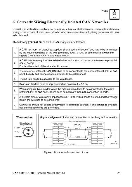
Wire structure Signal assignment of wire and connection of earthing and terminator<br />
CAN wire with connectors<br />
Figure: Structure and connection of wire<br />
CAN-CBM-COM1 <strong>Hardware</strong> <strong>Manual</strong> Rev. 1.1 29<br />
120 Ohm<br />
earth (PE)


