

Download complete product manual (PDF-File) - esd electronics, Inc.
Download complete product manual (PDF-File) - esd electronics, Inc.
Download complete product manual (PDF-File) - esd electronics, Inc.

Create successful ePaper yourself
Turn your PDF publications into a flip-book with our unique Google optimized e-Paper software.
Jumpers and Coding Switches<br />
configuration has been set in mode register via BR1 and that the correct polarity has been assigned to<br />
data bit D11 via BR7!<br />
Note:<br />
Principally, unipolar and bipolar output configurations can be selected on a VME-DAC1612. However,<br />
this is not recommendable, because other settings (at J130) are made simultaneously for all channels<br />
of the board.<br />
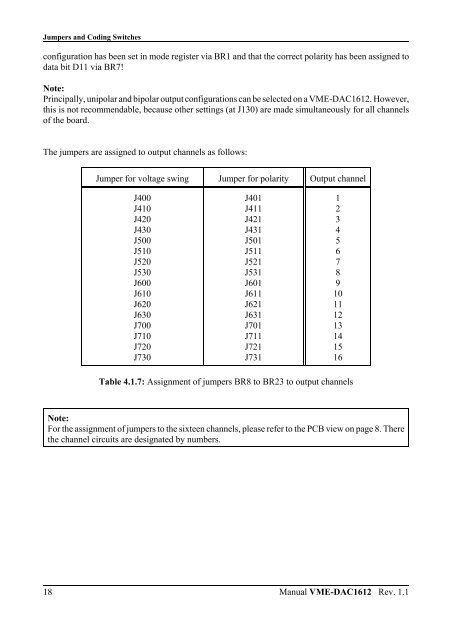
The jumpers are assigned to output channels as follows:<br />
18<br />
Jumper for voltage swing Jumper for polarity Output channel<br />
J400<br />
J410<br />
J420<br />
J430<br />
J500<br />
J510<br />
J520<br />
J530<br />
J600<br />
J610<br />
J620<br />
J630<br />
J700<br />
J710<br />
J720<br />
J730<br />
J401<br />
J411<br />
J421<br />
J431<br />
J501<br />
J511<br />
J521<br />
J531<br />
J601<br />
J611<br />
J621<br />
J631<br />
J701<br />
J711<br />
J721<br />
J731<br />
Table 4.1.7: Assignment of jumpers BR8 to BR23 to output channels<br />
Note:<br />
For the assignment of jumpers to the sixteen channels, please refer to the PCB view on page 8. There<br />
the channel circuits are designated by numbers.<br />
1<br />
2<br />
3<br />
4<br />
5<br />
6<br />
7<br />
8<br />
9<br />
10<br />
11<br />
12<br />
13<br />
14<br />
15<br />
16<br />
Manual VME-DAC1612 Rev. 1.1


