

Download complete product manual (PDF-File) - esd electronics, Inc.
Download complete product manual (PDF-File) - esd electronics, Inc.
Download complete product manual (PDF-File) - esd electronics, Inc.

Create successful ePaper yourself
Turn your PDF publications into a flip-book with our unique Google optimized e-Paper software.
Analog Outputs<br />
5.2 Operating Modes of the D/A-Converters<br />
5.2.1 Data Transfer<br />
Each of the 16 D/A-converters of the VME-DAC1612 has got its own access address. Writing the data<br />
at this address sets the D/A-converters und starts the conversion. The data has to be transferred word<br />
by word, because the conversion is started immediately when the WRITE signal is cancelled!<br />
Additionally, a mode register can be read in which the setting of the output polarity and the number of<br />
equipped channels can be evaluated. The mode register has already been described in the chapter<br />
‘Mode Register (J130)’ on page 14.<br />
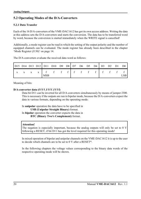
The D/A-converters evaluate the received data word as follows:<br />
D15 D14 D13 D12 D11 D10 D9 D8 D7 D6 D5 D4 D3 D2 D1 D0<br />
20<br />
x x x x f<br />
MSB<br />
Meaning of bits:<br />
f f f f f f f f f f f<br />
LSB<br />
D/A-converter data (f f f f .f f f f .f f f f)<br />
Data bit D11 can be inverted for all D/A-converters simultaneously by means of jumper J300.<br />
This is necessary if the outputs are run in bipolar mode, because the D/A-converters expect the<br />
data in various formats, depending on the operating mode:<br />
In unipolar operation the data have to be specified in<br />
USB (Unipolar Straight Binary) format.<br />
In bipolar operation the converter expects the data in<br />
BTC (Binary Two's Complement) format.<br />
Attention!<br />
The negation is especially important, because the analog outputs will only be set to 0 V<br />
following a RESET, if bit D11 has got the level required for this operating mode!<br />
In mixed operation of bipolar and unipolar channels on the VME-DAC1612 it is up to the user<br />
to decide which channels are to be set to 0 V after a RESET*.<br />
In the following chapters the voltage values corresponding to the binary data words of the<br />
respective operating mode will be shown.<br />
Manual VME-DAC1612 Rev. 1.1


