

Download complete product manual (PDF-File) - esd electronics, Inc.
Download complete product manual (PDF-File) - esd electronics, Inc.
Download complete product manual (PDF-File) - esd electronics, Inc.

You also want an ePaper? Increase the reach of your titles
YUMPU automatically turns print PDFs into web optimized ePapers that Google loves.
1. Overview<br />
1.1 Module Description<br />
P1 VMEbus<br />
VME Address<br />
and AM<br />
Decoder Logic<br />
Mode Register<br />
VME<br />
Data Bus<br />
Driver<br />
Address, Data and Control Bus<br />
Isolator IL715<br />
DC/DC-Converter<br />
+5V<br />
±12V<br />
Electrical Isolation<br />
Digital / Analog<br />
Converter<br />
DAC 813<br />
Digital / Analog<br />
Converter<br />
DAC 813<br />
4, 8 or 16<br />
D/A-Converter Channels<br />
Digital / Analog<br />
Converter<br />
DAC 813<br />
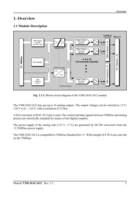
Fig. 1.1.1: Block-circuit diagram of the VME-DAC1612 module<br />
Connector at<br />
Front Panel<br />
Overview<br />
VMEbus P2<br />
The VME-DAC1612 has got up to 16 analog outputs. The output voltages can be selected as ±5 V,<br />
±10 V or 0 ...+10 V, with a resolution of 12 bits.<br />
A D/A-converter of DAC 813 type is used. The control and data signals between VMEbus and analog<br />
process are electrically insulated by means of fast digital couplers.<br />
The power supply of the analog side (±15 V, +5 V) are generated by DC/DC-converters from the<br />
+5 VMEbus power supply.<br />
The VME-DAC1612 is compatible to VMEbus Standard Rev. C. With a height of 4 TE it uses one slot<br />
on the VMEbus.<br />
Manual VME-DAC1612 Rev. 1.1 3<br />
P800 Outputs 1...8<br />
P801 Outputs 9...16<br />
P2 Outputs 1..16


