dissertation global and local fracture properties of metal matrix ...
dissertation global and local fracture properties of metal matrix ...
dissertation global and local fracture properties of metal matrix ...

You also want an ePaper? Increase the reach of your titles
YUMPU automatically turns print PDFs into web optimized ePapers that Google loves.
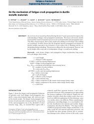
4.1.1.3. Fracture mechanics tests<br />
Section 4<br />
Compact tension (CT) specimens with a thickness <strong>of</strong> B = 12.5 mm, a width <strong>of</strong> W = 40 mm,<br />
<strong>and</strong> an initial crack length <strong>of</strong> a0 ≈ 20 mm are machined for the <strong>fracture</strong> mechanics tests <strong>of</strong> the<br />
cast MMCs (Fig. 4.4). The specimens have a longitudinal-transverse (LT) crack plane<br />
orientation.<br />
To insert the pre-crack in the CT specimens, they are subjected to cyclic compression loading<br />
with ∆K = 10 MPa m <strong>and</strong> further to cyclic tensile loading with ∆K = 5 MPa m . Fracture<br />
mechanics tests are conducted using the “ZWICK” testing machine which is equipped by a<br />
special computer program for <strong>fracture</strong> mechanics tests. The cross-head velocity is <strong>of</strong> 0.02<br />
mm/min for the reinforced materials, <strong>and</strong> 0.08 mm/min for unreinforced materials. A potential<br />
drop method is employed to determine the crack extension during the <strong>fracture</strong> mechanics<br />
tests. In this method, a constant electric current is sent through the specimen. An increase <strong>of</strong><br />
the crack length changes the electric resistance <strong>of</strong> the system <strong>and</strong> the measured potential.<br />
From the change <strong>of</strong> the potential, the crack extension can be calculated by the Johnson<br />
equation (4.1) [69],<br />
⎡<br />
⎤<br />
⎢<br />
⎥<br />
⎢<br />
⎥<br />
⎢<br />
π<br />
cosh<br />
⎥<br />
2W<br />
⎢<br />
⎥<br />
a = ⋅ arccos<br />
2W<br />
⎢<br />
⎥ , (4.1)<br />
π<br />
⎢<br />
⎡<br />
πy<br />
⎤<br />
⎥<br />
⎢<br />
⎢ cosh<br />
U<br />
⎥<br />
cosh<br />
⎥<br />
⎢<br />
⎢ ⋅ arccos<br />
2W<br />
⎥<br />
⎥<br />
⎢<br />
⎢U<br />
πa<br />
o<br />
o<br />
cos ⎥<br />
⎥<br />
⎣ ⎢⎣<br />
2W<br />
⎥⎦<br />
⎦<br />
where 2y is the distance between the points <strong>of</strong> the potential measurement, U is the current<br />
potential value, <strong>and</strong> Uo is the initial potential value.<br />
A schematic view <strong>of</strong> the potential drop method is presented in Figure 4.5. The electrical<br />
current intensity, I, is 10 A. The potential, U, is determined by a nanovoltmeter with an<br />
accuracy <strong>of</strong> ± 100 nV, which corresponds to an accuracy <strong>of</strong> the crack length <strong>of</strong> ± 0.01 mm. A<br />
clip-gage is used to determine the load line displacement <strong>of</strong> the specimen during the <strong>fracture</strong><br />
tests <strong>of</strong> the cast MMCs. The data on the load, load line displacement, <strong>and</strong> potential are saved<br />
in a file by the computer program every 10 s. The J-integral resistance curves were<br />
determined according to [73]. The J0.2/Bl -, Ji-values determined from these curves are given in<br />
Table 4.2, as well.<br />
32