

Theory, Design and Tests on a Prototype Module of a Compact ...
Theory, Design and Tests on a Prototype Module of a Compact ...
Theory, Design and Tests on a Prototype Module of a Compact ...

Create successful ePaper yourself
Turn your PDF publications into a flip-book with our unique Google optimized e-Paper software.
70 5. RADIOFREQUENCY MEASUREMENT<br />
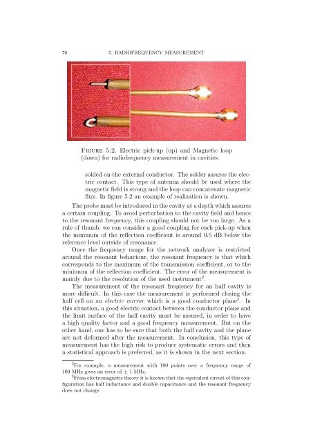
Figure 5.2. Electric pick-up (up) <str<strong>on</strong>g>and</str<strong>on</strong>g> Magnetic loop<br />
(down) for radi<strong>of</strong>requency measurement in cavities.<br />
solded <strong>on</strong> the external c<strong>on</strong>ductor. The solder assures the electric<br />
c<strong>on</strong>tact. This type <strong>of</strong> antenna should be used where the<br />
magnetic field is str<strong>on</strong>g <str<strong>on</strong>g>and</str<strong>on</strong>g> the loop can c<strong>on</strong>catenate magnetic<br />
flux. In figure 5.2 an example <strong>of</strong> realizati<strong>on</strong> is shown.<br />
The probe must be introduced in the cavity at a depth which assures<br />
a certain coupling. To avoid perturbati<strong>on</strong> to the cavity field <str<strong>on</strong>g>and</str<strong>on</strong>g> hence<br />
to the res<strong>on</strong>ant frequency, this coupling should not be too large. As a<br />
rule <strong>of</strong> thumb, we can c<strong>on</strong>sider a good coupling for each pick-up when<br />
the minimum <strong>of</strong> the reflecti<strong>on</strong> coefficient is around 0.5 dB below the<br />
reference level outside <strong>of</strong> res<strong>on</strong>ance.<br />
Once the frequency range for the network analyzer is restricted<br />
around the res<strong>on</strong>ant behaviour, the res<strong>on</strong>ant frequency is that which<br />
corresp<strong>on</strong>ds to the maximum <strong>of</strong> the transmissi<strong>on</strong> coefficient, or to the<br />
minimum <strong>of</strong> the reflecti<strong>on</strong> coefficient. The error <strong>of</strong> the measurement is<br />
mainly due to the resoluti<strong>on</strong> <strong>of</strong> the used instrument 2 .<br />
The measurement <strong>of</strong> the res<strong>on</strong>ant frequency for an half cavity is<br />
more difficult. In this case the measurement is performed closing the<br />
half cell <strong>on</strong> an electric mirror which is a good c<strong>on</strong>ductor plane 3 . In<br />
this situati<strong>on</strong>, a good electric c<strong>on</strong>tact between the c<strong>on</strong>ductor plane <str<strong>on</strong>g>and</str<strong>on</strong>g><br />
the limit surface <strong>of</strong> the half cavity must be assured, in order to have<br />
a high quality factor <str<strong>on</strong>g>and</str<strong>on</strong>g> a good frequency measurement. But <strong>on</strong> the<br />
other h<str<strong>on</strong>g>and</str<strong>on</strong>g>, <strong>on</strong>e has to be sure that both the half cavity <str<strong>on</strong>g>and</str<strong>on</strong>g> the plane<br />
are not deformed after the measurement. In c<strong>on</strong>clusi<strong>on</strong>, this type <strong>of</strong><br />
measurement has the high risk to produce systematic errors <str<strong>on</strong>g>and</str<strong>on</strong>g> then<br />
a statistical approach is preferred, as it is shown in the next secti<strong>on</strong>.<br />
2 For example, a measurement with 100 points over a frequency range <strong>of</strong><br />
100 MHz gives an error <strong>of</strong> ± 1 MHz.<br />
3 From electromagnetic theory it is known that the equivalent circuit <strong>of</strong> this c<strong>on</strong>figurati<strong>on</strong><br />
has half inductance <str<strong>on</strong>g>and</str<strong>on</strong>g> double capacitance <str<strong>on</strong>g>and</str<strong>on</strong>g> the res<strong>on</strong>ant frequency<br />
does not change.


