Theory, Design and Tests on a Prototype Module of a Compact ...
Theory, Design and Tests on a Prototype Module of a Compact ...
Theory, Design and Tests on a Prototype Module of a Compact ...
You also want an ePaper? Increase the reach of your titles
YUMPU automatically turns print PDFs into web optimized ePapers that Google loves.
74 5. RADIOFREQUENCY MEASUREMENT<br />
deduce the value <strong>of</strong> the quality factor; for brazed cavities, Q can be<br />
measured with accurate methods, or can be extrapolated from numerical<br />
calculati<strong>on</strong>s. Therefore, this procedure provides an indirect method<br />
to determine the shunt impedance Rsh.<br />
In the following a perturbati<strong>on</strong> technique is shown [34] which involve<br />
the measurement <strong>of</strong> the res<strong>on</strong>ant frequency <strong>of</strong> the cavity as a<br />
functi<strong>on</strong> <strong>of</strong> a certain perturbati<strong>on</strong> objects.<br />
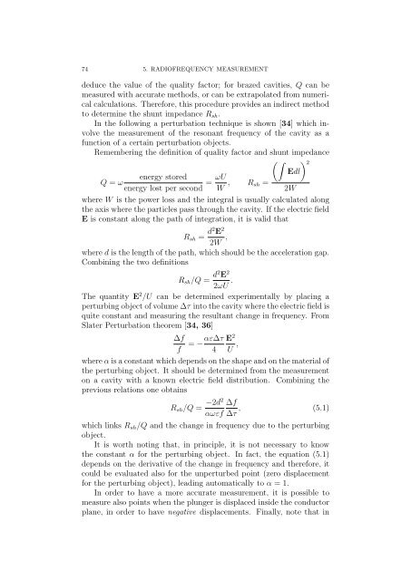
Remembering the definiti<strong>on</strong> <strong>of</strong> quality factor <str<strong>on</strong>g>and</str<strong>on</strong>g> shunt impedance<br />
energy stored ωU<br />
Q = ω<br />
=<br />
energy lost per sec<strong>on</strong>d W , Rsh<br />
2 Edl<br />
=<br />
2W<br />
where W is the power loss <str<strong>on</strong>g>and</str<strong>on</strong>g> the integral is usually calculated al<strong>on</strong>g<br />
the axis where the particles pass through the cavity. If the electric field<br />
E is c<strong>on</strong>stant al<strong>on</strong>g the path <strong>of</strong> integrati<strong>on</strong>, it is valid that<br />
Rsh = d2 E 2<br />
2W ,<br />
where d is the length <strong>of</strong> the path, which should be the accelerati<strong>on</strong> gap.<br />
Combining the two definiti<strong>on</strong>s<br />
Rsh/Q = d2 E 2<br />
2ωU .<br />
The quantity E 2 /U can be determined experimentally by placing a<br />
perturbing object <strong>of</strong> volume ∆τ into the cavity where the electric field is<br />
quite c<strong>on</strong>stant <str<strong>on</strong>g>and</str<strong>on</strong>g> measuring the resultant change in frequency. From<br />
Slater Perturbati<strong>on</strong> theorem [34, 36]<br />
∆f<br />
f<br />
= −αε∆τ<br />
4<br />
E 2<br />
U ,<br />
where α is a c<strong>on</strong>stant which depends <strong>on</strong> the shape <str<strong>on</strong>g>and</str<strong>on</strong>g> <strong>on</strong> the material <strong>of</strong><br />
the perturbing object. It should be determined from the measurement<br />
<strong>on</strong> a cavity with a known electric field distributi<strong>on</strong>. Combining the<br />
previous relati<strong>on</strong>s <strong>on</strong>e obtains<br />
Rsh/Q = −2d2 ∆f<br />
, (5.1)<br />
αωεf ∆τ<br />
which links Rsh/Q <str<strong>on</strong>g>and</str<strong>on</strong>g> the change in frequency due to the perturbing<br />
object.<br />
It is worth noting that, in principle, it is not necessary to know<br />
the c<strong>on</strong>stant α for the perturbing object. In fact, the equati<strong>on</strong> (5.1)<br />
depends <strong>on</strong> the derivative <strong>of</strong> the change in frequency <str<strong>on</strong>g>and</str<strong>on</strong>g> therefore, it<br />
could be evaluated also for the unperturbed point (zero displacement<br />
for the perturbing object), leading automatically to α = 1.<br />
In order to have a more accurate measurement, it is possible to<br />
measure also points when the plunger is displaced inside the c<strong>on</strong>ductor<br />
plane, in order to have negative displacements. Finally, note that in


