Performance of Special Extinguishment Agents for ... - UL.com
Performance of Special Extinguishment Agents for ... - UL.com
Performance of Special Extinguishment Agents for ... - UL.com

Create successful ePaper yourself
Turn your PDF publications into a flip-book with our unique Google optimized e-Paper software.
Issued: September 30, 2008<br />
ADD Test Facility<br />
Large Scale<br />
Fire Test Facility<br />
Heat Release Calorimeter & RDD<br />
PDPA Test Facility<br />
Conditioning<br />
Room<br />
Warehouse<br />
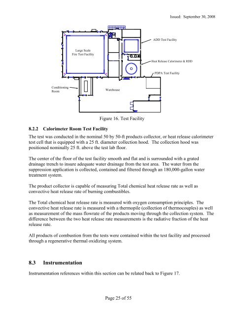
8.2.2 Calorimeter Room Test Facility<br />
Figure 16. Test Facility<br />
The test was conducted in the nominal 50 by 50-ft products collector, or heat release calorimeter<br />
test cell that is equipped with a 25 ft. diameter collection hood. The collection hood was<br />
positioned nominally 25 ft. above the test lab floor.<br />
The center <strong>of</strong> the floor <strong>of</strong> the test facility smooth and flat and is surrounded with a grated<br />
drainage trench to insure adequate water drainage from the test area. The water from the<br />
suppression application is collected, contained and filtered through an 180,000-gallon water<br />
treatment system.<br />
The product collector is capable <strong>of</strong> measuring Total chemical heat release rate as well as<br />
convective heat release rate <strong>of</strong> burning <strong>com</strong>bustibles.<br />
The Total chemical heat release rate is measured with oxygen consumption principles. The<br />
convective heat release rate is measured with a thermopile (collection <strong>of</strong> thermocouples) as well<br />
as measurement <strong>of</strong> the mass flowrate <strong>of</strong> the products moving through the collection system. The<br />
difference between the two heat release rate measurements is the radiative fraction <strong>of</strong> the heat<br />
release rate.<br />
All products <strong>of</strong> <strong>com</strong>bustion from the tests were contained within the test facility and processed<br />
through a regenerative thermal oxidizing system.<br />
8.3 Instrumentation<br />
Instrumentation references within this section can be related back to Figure 17.<br />
Page 25 <strong>of</strong> 55