

Liebert® Series 610™ UPS - Jonweb.net
Liebert® Series 610™ UPS - Jonweb.net
Liebert® Series 610™ UPS - Jonweb.net

You also want an ePaper? Increase the reach of your titles
YUMPU automatically turns print PDFs into web optimized ePapers that Google loves.
Operation<br />
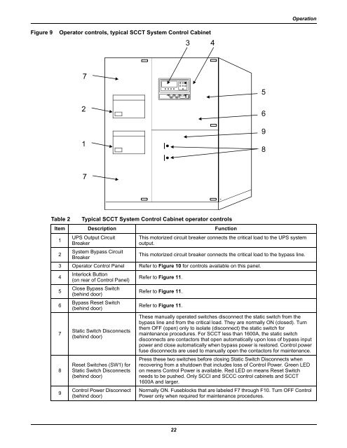
Figure 9<br />
Operator controls, typical SCCT System Control Cabi<strong>net</strong><br />
Table 2<br />
Typical SCCT System Control Cabi<strong>net</strong> operator controls<br />
Item Description Function<br />
1<br />
2<br />
<strong>UPS</strong> Output Circuit<br />
Breaker<br />
System Bypass Circuit<br />
Breaker<br />
This motorized circuit breaker connects the critical load to the <strong>UPS</strong> system<br />
output.<br />
This motorized circuit breaker connects the critical load to the bypass line.<br />
3 Operator Control Panel Refer to Figure 10 for controls available on this panel.<br />
4<br />
Interlock Button<br />
(on rear of Control Panel)<br />
Refer to Figure 11.<br />
5<br />
Close Bypass Switch<br />
(behind door)<br />
Refer to Figure 11.<br />
6<br />
Bypass Reset Switch<br />
(behind door)<br />
Refer to Figure 11.<br />
7<br />
8<br />
9<br />
Static Switch Disconnects<br />
(behind door)<br />
Reset Switches (SW1) for<br />
Static Switch Disconnects<br />
(behind door)<br />
Control Power Disconnect<br />
(behind door)<br />
These manually operated switches disconnect the static switch from the<br />
bypass line and from the critical load. They are normally ON (closed). Turn<br />
them OFF (open) only to isolate (disconnect) the static switch for<br />
maintenance procedures. For SCCT less than 1600A, the static switch<br />
disconnects are contactors that open automatically upon loss of bypass input<br />
power and close automatically when bypass power is restored. Control power<br />
fuse disconnects are used to manually open the contactors for maintenance.<br />
Press these two switches before closing Static Switch Disconnects when<br />
recovering from a shutdown that includes loss of Control Power. Green LED<br />
on means Control Power is available. Red LED on means Reset Switch<br />
needs to be pushed. Only SCCI and SCCC control cabi<strong>net</strong>s and SCCT<br />
1600A and larger.<br />
Normally ON. Fuseblocks that are labeled F7 through F10. Turn OFF Control<br />
Power only when required for maintenance procedures.<br />
22


