

Liebert® Series 610™ UPS - Jonweb.net
Liebert® Series 610™ UPS - Jonweb.net
Liebert® Series 610™ UPS - Jonweb.net

You also want an ePaper? Increase the reach of your titles
YUMPU automatically turns print PDFs into web optimized ePapers that Google loves.
Operation<br />
• Battery Test (MMU Only)—The optional battery test screen allows the operator to perform<br />
manual battery tests to determine the general condition of the battery system. The results of the<br />
last 10 tests are recorded in non-volatile storage and can be retrieved through the battery test<br />
results screen.<br />
• Battery Temp Compensation Charging (MMU Only)—The optional battery temperature<br />
sensing unit, when installed, automatically reduces the float charge voltage in response to<br />
increases in battery temperature. The nominal float voltage is 540VDC (2.25 volts per cell) at<br />
25°C. This float voltage is automatically reduced 5VDC for each temperature rise of 5°C. The LCD<br />
indicates whether the temperature compensation circuit is active.<br />
3.2.2 SCC Monitor/Mimic Display Screen<br />
From SCC Master Menu move the highlighted cursor to MONITOR/MIMIC DISPLAY. Press the<br />
Select pad and the Monitor/Mimic screen is displayed.<br />
The Monitor/Mimic display screen is a simplified block diagram of the <strong>UPS</strong> system. This screen gives<br />
the operator an overall view of the power flow through the <strong>UPS</strong> system. The screen consists of three<br />
major sections: the input/<strong>UPS</strong> metering section, the load metering section and the status and alarm<br />
message areas. The metered parameter values on the Monitor/Mimic screen are updated at one-second<br />
intervals.<br />
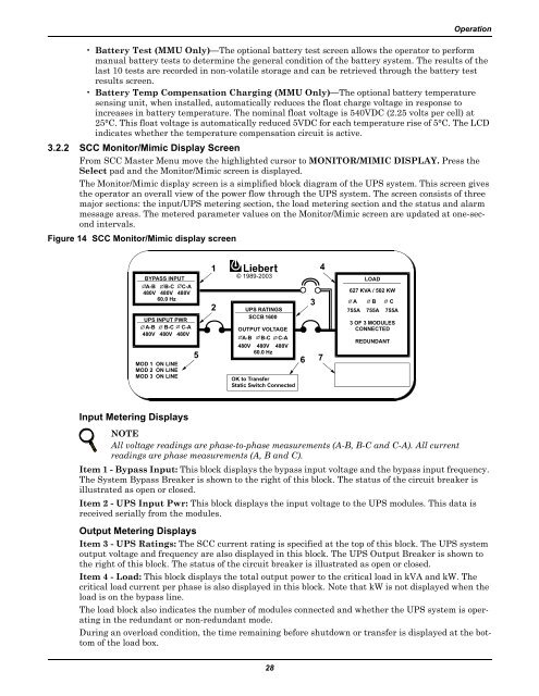
Figure 14 SCC Monitor/Mimic display screen<br />
BYPASS INPUT<br />
A-B B-C C-A<br />
480V 480V 480V<br />
60.0 Hz<br />
<strong>UPS</strong> INPUT PWR<br />
A-B B-C C-A<br />
480V 480V 480V<br />
MOD 1 ON LINE<br />
MOD 2 ON LINE<br />
MOD 3 ON LINE<br />
5<br />
1<br />
2<br />
© 1989-2003<br />
<strong>UPS</strong> RATINGS<br />
SCCB 1600<br />
OUTPUT VOLTAGE<br />
A-B B-C C-A<br />
480V 480V 480V<br />
60.0 Hz<br />
OK to Transfer<br />
Static Switch Connected<br />
3<br />
4<br />
6 7<br />
LOAD<br />
627 KVA / 502 KW<br />
A B C<br />
755A 755A 755A<br />
3 OF 3 MODULES<br />
CONNECTED<br />
REDUNDANT<br />
Input Metering Displays<br />
NOTE<br />
All voltage readings are phase-to-phase measurements (A-B, B-C and C-A). All current<br />
readings are phase measurements (A, B and C).<br />
Item 1 - Bypass Input: This block displays the bypass input voltage and the bypass input frequency.<br />
The System Bypass Breaker is shown to the right of this block. The status of the circuit breaker is<br />
illustrated as open or closed.<br />
Item 2 - <strong>UPS</strong> Input Pwr: This block displays the input voltage to the <strong>UPS</strong> modules. This data is<br />
received serially from the modules.<br />
Output Metering Displays<br />
Item 3 - <strong>UPS</strong> Ratings: The SCC current rating is specified at the top of this block. The <strong>UPS</strong> system<br />
output voltage and frequency are also displayed in this block. The <strong>UPS</strong> Output Breaker is shown to<br />
the right of this block. The status of the circuit breaker is illustrated as open or closed.<br />
Item 4 - Load: This block displays the total output power to the critical load in kVA and kW. The<br />
critical load current per phase is also displayed in this block. Note that kW is not displayed when the<br />
load is on the bypass line.<br />
The load block also indicates the number of modules connected and whether the <strong>UPS</strong> system is operating<br />
in the redundant or non-redundant mode.<br />
During an overload condition, the time remaining before shutdown or transfer is displayed at the bottom<br />
of the load box.<br />
28


