

Liebert® Series 610™ UPS - Jonweb.net
Liebert® Series 610™ UPS - Jonweb.net
Liebert® Series 610™ UPS - Jonweb.net

You also want an ePaper? Increase the reach of your titles
YUMPU automatically turns print PDFs into web optimized ePapers that Google loves.
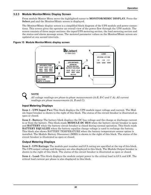
3.2.3 Module Monitor/Mimic Display Screen<br />
Operation<br />
From module Master Menu move the highlighted cursor to MONITOR/MIMIC DISPLAY. Press the<br />
Select pad and the Monitor/Mimic screen is displayed.<br />
The Monitor/Mimic display screen is a simplified block diagram of the <strong>UPS</strong> module and power connections.<br />
This screen gives the operator an overall view of the power flow through the <strong>UPS</strong> module. The<br />
screen consists of three major sections: the input/<strong>UPS</strong> metering section, the load metering section and<br />
the status and alarm message areas. The metered parameter values on the Monitor/Mimic screen are<br />
updated at one second intervals.<br />
Figure 15 Module Monitor/Mimic display screen<br />
© 1989-2003<br />
4<br />
LOAD<br />
270 KVA / 217 KW<br />
<strong>UPS</strong> INPUT PWR<br />
A-B B-C C-A<br />
480V 480V 480V<br />
350A 350A 350A<br />
BATTERY<br />
VOLTS 540<br />
AMPS 15 CHARG<br />
1<br />
2<br />
<strong>UPS</strong> RATINGS<br />
AP648-84<br />
RATED 400 KVA<br />
OUTPUT VOLTAGE<br />
A-B B-C C-A<br />
480V 480V 480V<br />
60.0 Hz<br />
3<br />
5<br />
A B C<br />
325A 325A 325A<br />
NOTE<br />
All voltage readings are phase-to-phase measurements (A-B, B-C and C-A). All current<br />
readings are phase measurements (A, B and C).<br />
Input Metering Displays<br />
Item 1 - <strong>UPS</strong> Input Pwr: This block displays the <strong>UPS</strong> module input voltage and current. The Module<br />
Input breaker is shown to the right of this block. The status of the circuit breaker is illustrated as<br />
open or closed.<br />
Item 2 - Battery: The battery block displays the DC bus voltage and the charge or discharge current<br />
to or from the battery. This block reads MODULE DC BUS when the battery circuit breaker is open<br />
and BATTERY when the battery circuit breaker is closed during normal operation. This block reads<br />
BATTERY EQUALIZE when the battery equalize charge voltage is used to recharge the battery.<br />
This block also shows BATTERY TEMPERATURE when the battery temperature sensor option is<br />
installed. The Module Battery Disconnect (MBD) is shown to the right of this block. The status of the<br />
circuit breaker is illustrated as open or closed.<br />
Output Metering Displays<br />
Item 3 - <strong>UPS</strong> Ratings: The module part number and kVA rating are specified at the top of this block.<br />
The <strong>UPS</strong> output voltage and frequency are also displayed in this block. The Module Output breaker is<br />
shown to the right of this block. The status of the circuit breaker is illustrated as open or closed.<br />
Item 4 - Load: This block displays the module output power to the critical load in kVA and kW. The<br />
critical load current per phase is also displayed in this block.<br />
30


