solaris 24PC 30PC - Heatline
solaris 24PC 30PC - Heatline
solaris 24PC 30PC - Heatline

Create successful ePaper yourself
Turn your PDF publications into a flip-book with our unique Google optimized e-Paper software.
<strong>solaris</strong> <strong>24PC</strong>, <strong>30PC</strong><br />
27<br />
18. Component Replacement<br />
CAUTION!<br />
While there are no substances harmful to health<br />
contained within this appliance, some component<br />
parts of the boiler (insulation pads, gaskets and rope<br />
seals) are manufactured from man made fibres.<br />
When damaged or broken these fibres may cause a<br />
temporary irritation. High dust levels may irritate<br />
eyes and upper respiratory system. It is important<br />
therefore, that sensible precautions are applied<br />
when exchanging components.<br />
18.1 Ensure that both the electrical and gas<br />
supplies to the boiler are isolated before<br />
replacing any component part.<br />
18.2 To prevent the need to drain the entire<br />
heating system when replacing the boiler's<br />
integral pump, expansion vessel, safety relief<br />
valve and pressure sensor, the boiler’s<br />
hydraulic circuit may be isolated from the<br />
central heating circuit by closing the boilers<br />
isolation valves. Opening the drain valve at the<br />
back of the pump will then drain the boiler’s<br />
hydraulic circuit.<br />
18.3 For replacement of the following<br />
components it will be necessary to remove the<br />
boiler casing panels as described in Section<br />
17.<br />
18.4 Domestic hot water sensor<br />
Figure 31<br />
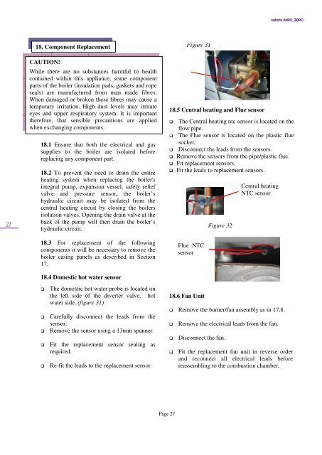
18.5 Central heating and Flue sensor<br />
The Central heating ntc sensor is located on the<br />
flow pipe.<br />
The Flue sensor is located on the plastic flue<br />
socket.<br />
Disconnect the leads from the sensors.<br />
Remove the sensors from the pipe/plastic flue.<br />
Fit replacement sensors.<br />
Fit the leads to replacement sensors.<br />
Flue NTC<br />
sensor<br />
Figure 32<br />
Central heating<br />
NTC sensor<br />
<br />
<br />
<br />
<br />
<br />
The domestic hot water probe is located on<br />
the left side of the diverter valve, hot<br />
water side. (figure 31)<br />
Carefully disconnect the leads from the<br />
sensor.<br />
Remove the sensor using a 13mm spanner.<br />
Fit the replacement sensor sealing as<br />
required.<br />
Re-fit the leads to the replacement sensor<br />
18.6 Fan Unit<br />
Remove the burner/fan assembly as in 17.8.<br />
<br />
<br />
<br />
Remove the electrical leads from the fan.<br />
Disconnect the fan.<br />
Fit the replacement fan unit in reverse order<br />
and reconnect all electrical leads before<br />
reassembling to the combustion chamber.<br />
Page 27