PcB - High Frequency Electronics
PcB - High Frequency Electronics
PcB - High Frequency Electronics

Create successful ePaper yourself
Turn your PDF publications into a flip-book with our unique Google optimized e-Paper software.
<strong>High</strong> <strong>Frequency</strong> Design<br />
Satellite Data Transmission<br />
Satellite Data Transmitting<br />
Systems and In-Orbit<br />
Performance<br />
By D.V. Ramana and Jolie. R<br />
Abstract<br />
The system block An Indian Remote<br />
diagram, specifications, Sensing Satellite—<br />
qualification tests and Resoucesat-2—was<br />
link calculations of launched successfully<br />
X-band data transmitting into a polar, sun-synchronous<br />
orbit on 20th April,<br />
systems are discussed.<br />
2011. It carries remote<br />
sensing payloads capable<br />
of operating in four spectral bands. The two<br />
types of payloads are Linear Imaging Self<br />
Scanning Sensors (LISSIV and LISSIII) and<br />
Advanced Wide Field Scanner (AWIFS). The<br />
payload data is transmitted through X-band<br />
data transmitters employing QPSK modulation.<br />
The modulated data is amplified using<br />
high gain Travelling Wave Tube Amplifiers<br />
(TWTAs) for downlink data transmission. The<br />
system block diagram, specifications, qualification<br />
tests, and link calculations of the<br />
X-band data transmitting systems are discussed.<br />
This paper also discusses the in-orbit<br />
performance of the X-band data transmitting<br />
systems.<br />
Introduction<br />
The space to earth communication link<br />
basically depends on the RF carrier frequency,<br />
modulation, data rate, figure of merit (G/T) of<br />
the ground station and onboard Effective<br />
Isotropic Radiated Power (EIRP). This would<br />
help in understanding the power level requirements<br />
of the data transmitters and gain of<br />
ground and onboard antenna systems for<br />
desired quality of data reception.<br />
The X-band data transmitting system on<br />
Resourcesat-2 performs the following functions:<br />
• Generates two X-Band carriers at 8125<br />
MHz and 8300 MHz.<br />
• Accepts data from the LISS-IV and<br />
LISS-III + AWIFS cameras.<br />
• Modulates the above data on the two<br />
independent X-band carriers.<br />
• Transmits the modulated carriers to<br />
ground after suitable amplification and<br />
filtering.<br />
The data handling system is essentially<br />
built around two chains, the LISS IV chain<br />
and the LISS III chain, each handling 105<br />
Mbps of data. The two chains are end to end<br />
independent.<br />
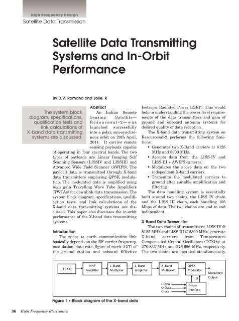
X-Band Data Transmitter<br />
The two chains of transmitters, LISS IV @<br />
8125 MHz and LISS III @ 8300 MHz, generate<br />
X-band carriers from Temperature<br />
Compensated Crystal Oscillators (TCXOs) at<br />
270.833 MHz and 276.666 MHz, respectively.<br />
The two chains are operated simultaneously.<br />
T CX O<br />
V HF<br />
A mplifier<br />
L -B and<br />
Multiplier<br />
L -B and<br />
A mplifier<br />
X -B and<br />
Multiplier<br />
I-Data<br />
Q-Data<br />
Clock<br />
QPSK<br />
Modulator<br />
I<br />
Q<br />
Driver<br />
Interface<br />
Modulated<br />
Output<br />
Figure 1 • Block diagram of the X-band data<br />
36 <strong>High</strong> <strong>Frequency</strong> <strong>Electronics</strong>