

advances in numerical modeling of manufacturing processes
advances in numerical modeling of manufacturing processes
advances in numerical modeling of manufacturing processes

Create successful ePaper yourself
Turn your PDF publications into a flip-book with our unique Google optimized e-Paper software.
TRANS. INDIAN INST. MET., VOL. 57, NO. 4, AUGUST 2004<br />
Fig. 16: The geometric parameters <strong>of</strong> the gate and the design values chosen <strong>in</strong> the optimization.<br />
symmetry, a two-cyl<strong>in</strong>der model was used for<br />
simulation as it reasonably represents the fill<strong>in</strong>g<br />
characteristics <strong>of</strong> the entire block s<strong>in</strong>ce cross-flow<br />
between cyl<strong>in</strong>ders is very less.<br />
The results and comparisons <strong>of</strong> the simulations are<br />
shown <strong>in</strong> Fig. 17. In the simulation <strong>of</strong> the exist<strong>in</strong>g<br />
design, the runner system is <strong>in</strong>cluded while <strong>in</strong> the<br />
simulation <strong>of</strong> the new design, a runner system has<br />
not been <strong>in</strong>cluded. Consequently, <strong>in</strong> the new design<br />
the metal reaches the gate very fast, whereas <strong>in</strong> the<br />
exist<strong>in</strong>g design the metal reaches the gate only after<br />
0.1 sec. So the comparison plots have been made at<br />
the same times that have elapsed after the metal<br />
reached the <strong>in</strong>gate. The figures only show the regions<br />
that have been filled with metal.<br />
In all the three figures, we can see that <strong>in</strong> the case<br />
<strong>of</strong> the new design the fill<strong>in</strong>g is faster than the exist<strong>in</strong>g<br />
<strong>in</strong>gate design case. The bear<strong>in</strong>g areas get filled much<br />
faster and hence there is more time for the thick<br />
sections to solidify and this could lead to reduced<br />
shr<strong>in</strong>kage defects <strong>in</strong> the region. The vent region and<br />
the adjo<strong>in</strong><strong>in</strong>g areas also get filled at almost the same<br />
time and hence there is lesser chance <strong>of</strong> entrapped<br />
gas porosity <strong>in</strong> that region <strong>in</strong> the new design. From<br />
the above comparison it can be seen that the new<br />
<strong>in</strong>gate design comb<strong>in</strong>ed with a larger <strong>in</strong>gate velocity<br />
favors better fill<strong>in</strong>g <strong>in</strong> the bear<strong>in</strong>g and the vent regions.<br />
This will help <strong>in</strong> the reduction <strong>of</strong> entrapped gas<br />
porosity dur<strong>in</strong>g fill<strong>in</strong>g and shr<strong>in</strong>kage porosity dur<strong>in</strong>g<br />
the solidification stage.<br />
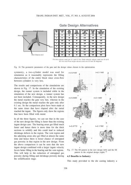
Fig. 17: The fill pattern <strong>in</strong> the new design (left) and the fill<br />
pattern <strong>in</strong> the orig<strong>in</strong>al design (right) 45<br />
4.5 Benefits to Industry<br />
This study provided to the die cast<strong>in</strong>g <strong>in</strong>dustry a<br />
358


