SIMATIC PCS 7 process control system
SIMATIC PCS 7 process control system
SIMATIC PCS 7 process control system

You also want an ePaper? Increase the reach of your titles
YUMPU automatically turns print PDFs into web optimized ePapers that Google loves.
System-wide engineering<br />
with the central engineering <strong>system</strong><br />
Import/<br />
Export<br />
Assistant<br />
CFC/SFC<br />
Engineering for<br />
automation<br />
Technological<br />
function blocks<br />
Libraries<br />
HW<br />
Config<br />
<strong>PCS</strong> 7 engineering<br />
Graphics<br />
Designer<br />
Faceplate<br />
Designer<br />
<strong>SIMATIC</strong> Manager /<br />
uniform database<br />
Engineering for network/<br />
communication/hardware<br />
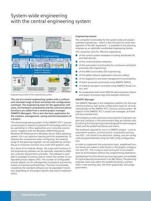
Engineering toolset of the engineering <strong>system</strong><br />
<strong>SIMATIC</strong><br />
BATCH<br />
Engineering<br />
for fail-safe<br />
<strong>system</strong>s<br />
S7<br />
F Systems<br />
OS<br />
engineering<br />
<strong>SIMATIC</strong><br />
PDM<br />
Parameterization<br />
of<br />
field devices<br />
The use of a central engineering <strong>system</strong> with a uniform<br />
and matched range of tools minimizes the configuration<br />
overhead. The engineering tools for the application software,<br />
the hardware components and the communications<br />
functions are called from a central project manager<br />
(<strong>SIMATIC</strong> Manager). This is also the basic application for<br />
the creation, management, saving and documentation of<br />
a project.<br />
The central engineering <strong>system</strong> of the <strong>SIMATIC</strong> <strong>PCS</strong> 7 <strong>process</strong><br />
<strong>control</strong> <strong>system</strong> is based on powerful PC technology which can<br />
be used either in office applications or in industrial environments.<br />
Together with the Windows 2000 Professional,<br />
Windows XP Professional or Windows Server 2003 operating<br />
<strong>system</strong>, this is an optimum starting point for engineering. To<br />
improve the convenience when configuring, the working<br />
range of the planning engineer can be extended by connecting<br />
up to 4 <strong>process</strong> monitors via a multi-VGA graphics card.<br />
As a result of its modular design, the scope and functions of<br />
the engineering software can be optimally matched to different<br />
customer requirements and tasks. The software is available<br />
in packages of various sizes to match the number of configurable<br />
<strong>process</strong> objects (PO). The number of configurable<br />
<strong>process</strong> objects can be subsequently increased at any time by<br />
means of engineering PowerPacks. The basic functionality<br />
covered by the standard software can be expanded if necessary<br />
depending on the project-specific task and its implementation.<br />
Engineering toolset<br />
The complete functionality for the <strong>system</strong>-wide and projectoriented<br />
engineering – which is also the basis for asset management<br />
of the I&C equipment – is available to the planning<br />
engineer as an optimally coordinated engineering toolset.<br />
This comprises tools for effective engineering<br />
■ of the <strong>control</strong> <strong>system</strong> hardware including distributed I/O<br />
and field devices,<br />
■ of the communication networks,<br />
■ of the automation functionality for continuous and batch<br />
<strong>process</strong>es (AS engineering)<br />
■ of the HMI functionality (OS engineering),<br />
■ of the safety-relevant applications (<strong>process</strong> safety),<br />
■ of the diagnostics and asset management functionalities,<br />
■ of batch <strong>process</strong>es automated using <strong>SIMATIC</strong> BATCH,<br />
■ of material transport <strong>control</strong>led using <strong>SIMATIC</strong> Route Control,<br />
and<br />
■ for cooperation with host CAD/CAE planning tools (import<br />
and export of <strong>process</strong> tags and example solutions).<br />
<strong>SIMATIC</strong> Manager<br />
The <strong>SIMATIC</strong> Manager is the integration platform for the engineering<br />
toolset as well as the configuration basis for all engineering<br />
tasks of the <strong>SIMATIC</strong> <strong>PCS</strong> 7 <strong>process</strong> <strong>control</strong> <strong>system</strong>. All<br />
aspects of the <strong>SIMATIC</strong> <strong>PCS</strong> 7 project are managed, archived<br />
and documented here.<br />
Technologists as well as <strong>process</strong> and production engineers can<br />
plan and configure in the environment they are familiar with<br />
by utilizing the engineering toolset designed for technological<br />
needs and the predefined blocks and charts.<br />
The hardware required for use in a <strong>SIMATIC</strong> project – such as<br />
automation <strong>system</strong>s, communication components and <strong>process</strong><br />
I/Os – are stored in an electronic catalog, and are configured<br />
and parameterized using the HW Config configuration<br />
tool.<br />
In order to implement the automation logic, predefined function<br />
blocks are linked to other blocks in the graphic configuration<br />
tool CFC. This is easy to learn and quick to accomplish<br />
even by technologists without any programming experience.<br />
Standardized function blocks (<strong>process</strong> tag types) are available<br />
for typical devices/components in an I&C library. The planning<br />
engineer need only select the predefined blocks, position<br />
them in the working area, link them graphically, and assign<br />
parameters.<br />
12 Engineering <strong>system</strong>