SIMATIC PCS 7 process control system
SIMATIC PCS 7 process control system
SIMATIC PCS 7 process control system

You also want an ePaper? Increase the reach of your titles
YUMPU automatically turns print PDFs into web optimized ePapers that Google loves.
Engineering software<br />
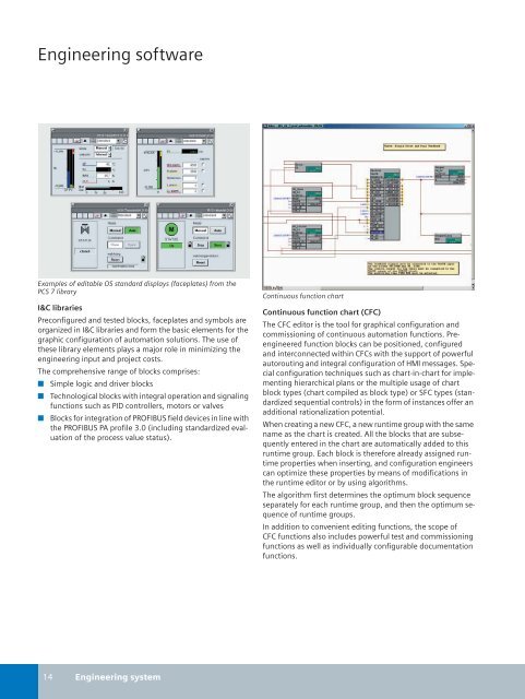
Examples of editable OS standard displays (faceplates) from the<br />
<strong>PCS</strong> 7 library<br />
I&C libraries<br />
Preconfigured and tested blocks, faceplates and symbols are<br />
organized in I&C libraries and form the basic elements for the<br />
graphic configuration of automation solutions. The use of<br />
these library elements plays a major role in minimizing the<br />
engineering input and project costs.<br />
The comprehensive range of blocks comprises:<br />
■ Simple logic and driver blocks<br />
■ Technological blocks with integral operation and signaling<br />
functions such as PID <strong>control</strong>lers, motors or valves<br />
■ Blocks for integration of PROFIBUS field devices in line with<br />
the PROFIBUS PA profile 3.0 (including standardized evaluation<br />
of the <strong>process</strong> value status).<br />
Continuous function chart<br />
Continuous function chart (CFC)<br />
The CFC editor is the tool for graphical configuration and<br />
commissioning of continuous automation functions. Preengineered<br />
function blocks can be positioned, configured<br />
and interconnected within CFCs with the support of powerful<br />
autorouting and integral configuration of HMI messages. Special<br />
configuration techniques such as chart-in-chart for implementing<br />
hierarchical plans or the multiple usage of chart<br />
block types (chart compiled as block type) or SFC types (standardized<br />
sequential <strong>control</strong>s) in the form of instances offer an<br />
additional rationalization potential.<br />
When creating a new CFC, a new runtime group with the same<br />
name as the chart is created. All the blocks that are subsequently<br />
entered in the chart are automatically added to this<br />
runtime group. Each block is therefore already assigned runtime<br />
properties when inserting, and configuration engineers<br />
can optimize these properties by means of modifications in<br />
the runtime editor or by using algorithms.<br />
The algorithm first determines the optimum block sequence<br />
separately for each runtime group, and then the optimum sequence<br />
of runtime groups.<br />
In addition to convenient editing functions, the scope of<br />
CFC functions also includes powerful test and commissioning<br />
functions as well as individually configurable documentation<br />
functions.<br />
14 Engineering <strong>system</strong>